
1
2 Ohm Nominal
Component
Speaker System
OWNER’S MANUAL
60.pub
page 1
Friday, September 10, 1999 21:03

2
HARDWARE
AND
CONNECTOR
PARTS LIST
PROJECT
SPL 6
SPL 60 Component Speaker System
Congratulations on your purchase of the Soundstream SPL 60
Component Speaker System. When used with a high quality 2 ohm
rated power amplifier, the SPL 60 will provide exceptional
performance.
As with all high quality car audio components, professional installation
is recommended. Your dealer’s knowledge and experience can ensure
a problem-free, cosmetically integrated installation. If you plan on
installing the SPL 60 speaker system yourself, please review this
Owner’s Manual first before attempting installation. In addition, it’s a
good idea to keep the manual for future reference.
SPL 6 Serial Number _______________________________________
SPL 1 Serial Number _______________________________________
Date of Purchase ___________________________________________
Date of Installation _________________________________________
Dealer’s Name ____________________________________________
Before beginning your installation, please check to see that the number
of parts contained in your box match the list below:
Hardware
4 each - Stainless steel tweeter spring clips (for SPL 1 flush mount cup)
2 each - Flush-mount cups for SPL1 (for SPL 1 flush mount cup)
2 each - 1/4" 6-32 machine screws (for SPL 1 flush mount cup)
2 each - Surface-mount kit for SPL1 (includes 2 flat head screws)
20 each - 1” #8 sheet metal screws (for mounting SPL6 and SPL6x)
Connectors
4 each -
1
/
4
” tab female Gold insulated slip-on connectors (for the SPL
6 woofers)
12 each - Gold Spade connectors (for connecting to crossover)
4 each -
1
/
8
” Gold female bullet connectors with vinyl insulators (for
connecting SPL 1 to speaker wire)
60.pub
page 2
Friday, September 10, 1999 21:03

3
FEATURES
LOCATION
AND
MOUNTING
SPL 6 Midrange / Woofer
The SPL 6 is an excellent performer with a combination of high
sensitivity, solid bass and smooth response throughout the audible
range.
• Lightweight Cone designed for good rigidity and high sensitivity
• 2 Ohm Voice Coil for increased output
SPL 1 Aluminum Dome Neodymium Tweeter
The SPL 1 tweeter is a high performance 1” Neodymium tweeter
designed to deliver outstanding high frequency reproduction.
• Black Aluminum 1" dome for improved power handling and
linear response
• Ferrofluid-immersed Voice Coil enhances heat dissipation
• Vented Aluminum Voice Coil Former for superb heat dissipation
and high power handling
SPL 6X Passive Crossover Network
The SPL 6X crossover consists of high quality, multi-element
components with a two position tweeter level control. This allows
tailoring high frequency output to the installation and individual
preferences.
• 24 dB/octave Acoustic Summation Crossover Slopes
• Variable tweeter control for added flexibility
• Dynamic tweeter protection allows for improved power handling
and continuous output
• Ultra-low DCR Inductors for minimal signal loss (High power
Ferrite in woofer path)
2 Ohm Nominal System Impedance
The 2 Ohm impedance design of the SPL 60 system provides an overall
3 dB increase in output compared to a 4 Ohm design.
•Effectively a doubling of Sound Pressure Level -- with the same
amplifier voltage output
•More stable, phase coherent load than two 4 Ohm speakers
operating in parallel
60.pub
page 3
Friday, September 10, 1999 21:03

4
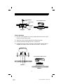
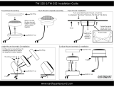
Flush Mounting:
1) Cut a 2 1/16” (52mm) diameter hole through the
mounting surface. If the surface is covered with
cloth or carpet, be careful not to tear or pull the
material. Sometimes it is a good idea to peel the
material away, and then trim it by hand.
2) Secure the cup in the mounting cutout by using
the spring clips and screw provided. Slip the
spring clips through the bottom of the cup and
tighten the screw until the cup is firmly seated.
See Figure 1.
3) Once the cup is secure, mount the tweeter into
the cup making sure to first pass the tweeter
wires through the openings in the cup. Turn the
outer swivel ring, (not the tweeter) clockwise to
lock it into place. See Figure 2. The tweeter
may be tilted approximately 15 degrees to
optimize dispersion and imaging.
INSTALLING
THE
TWEETER
The first step in a successful installation is thorough
planning. Choose the location for your speaker
components carefully. Follow these suggestions to
ensure proper imaging and the best performance:
• Select a location where each tweeter and
midrange/woofer can be mounted close to each
other. A good rule of thumb is a maximum of
one foot from cone to tweeter.
• Choose a location that offers the least
obstruction of sound to your ears.
• Try to mount the components on the same plane.
• Always check behind the chosen mounting
locations to make sure that there are no
obstructions (e.g., trunk springs, gas tank,
window tracks) or wires in the way, as well as to
make sure that there is ample support on which
to mount the components.
LOCATION
AND
MOUNTING
60.pub
page 4
Friday, September 10, 1999 21:03

5
1
/
4
” 6-32 machine
screw
Flush mount
cup
Mounting
surface
FIGURE 2
FIGURE 1
Spring
clip
Surface Mounting:
1) Drill one 5/16" diameter hole for the tweeter lead wires and two pilot
holes for the mounting screws.
2) Attach the surface mount plate with two flat head screws.
3) Pass the lead wires through the hole. See figure 3.
4) Engage the locking holes on the back of the tweeter onto the tabs on
the plate and rotate counter-clockwise until locked. See figure 4.
FIGURE 3
FIGURE 4
Turn Counter-Clockwise to Lock
Turn Clockwise to Lock
60.pub
page 5
Friday, September 10, 1999 21:03

6
INSTALLING
THE SPL 6
MIDRANGE/
WOOFER
MOUNTING
THE SPL 6X
CROSSOVER
The SPL 6 Midrange/Woofer can be mounted on
the front or rear of a panel; gaskets are provided
for both options. The bolt hole configuration will fit
a variety of American, European and Asian OEM
patterns making it ideal for direct placement. Best
performance is achieved when the speaker is
securely mounted to a door panel or rear deck.
There should be no gaps between the speaker and
the mounting surface, as this will impair its low
frequency performance. Be certain that both the
panel and the speaker are securely mounted to
prevent unwanted vibration.
1) Mark the speaker location by using the
template provided.
2) Cut the opening and debur the edges with a
file.
3) Hold the speaker in place against the
mounting surface and mark the mounting bolt
holes.
6) Drill the appropriate size hole for the screws
provided.
7) Place the SPL 6 into the trim ring, make the
speaker wire connections, then install the
speaker/trim ring assembly to the panel using
The SPL 6X Passive Crossover can be mounted
in virtually any location inside the vehicle. Be
sure not to mount the SPL 6X outside the vehicle,
or in a location where it may be exposed to dirt or
moisture (e.g., the engine compartment, inside a
wheel housing, at the bottom of a leaky trunk,
inside a door).
60.pub
page 6
Friday, September 10, 1999 21:03

7
TWEETER
LEVEL
CONTROL
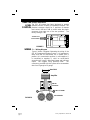
Tweeter Attenuation
The SPL 60 system has been designed to provide
optimum sound in a variety of installation locations. The
provided crossover allows for 2 positions of tweeter
level control, 0dB and -3dB. A switch under the plastic
crossover cover sets one of the two positions. The
factory setting is 0 dB.
SPL 6 Wiring Diagram
Figure 6 shows a diagram illustrating the wiring of the
SPL 60 Component Speaker System. It is important to
make sure that all connections are in phase; that is
positive (+) is connected to positive (+), and negative (-)
is connected to negative (-) since an out-of-phase
connection will cause a dislocated image and low bass
output. We suggest using premium cable. The
connectors provided with this system will accommodate
wire from 12 gauge to 16 gauge.
WIRING
Head Unit
Amplifier
SPL 1 Tweeter
SPL 6 Woofer
SPL 6X
Crossover
FIGURE 6
Tweeter Level
Control Switch
FIGURE 5
60.pub
page 7
Friday, September 10, 1999 21:03

8
120 Blue Ravine Road Folsom California 95630 USA
tel 916.351.1288 fax 916.351.0414
SPECIFICATIONS
SPL 60 System Specifications
Frequency Response 55 Hz - 20,000 Hz ±3dB
Sensitivity 94 dB SPL at 1 meter (2.83 Volts)
100 dB SPL at .5 meter (2.83 Volts)
Continuous Power Handling 50 watts
Peak Program Power Handling 100 watts
Nominal Impedance
2Ω
Crossover Slope Rate 24 dB/octave ASC
Crossover Dimensions 2 5/8” (W) x 1 3/8” (H) x 4 3/4” (D)
SPL 6 Midrange/Woofer
Frequency Response 55 Hz - 3200 Hz ±3dB
Continuous Power Handling 50 watts with SPL 6X Crossover
Peak Program Power Handling 100 watts with SPL 6X Crossover
Sensitivity 94 dB SPL at 1 meter (2.83 Volts)
Nominal Impedance
2Ω
Nominal Driver Diameter 6 1/2”
Mounting Cut-Out Diameter 5 5/8”
Mounting Depth 2 3/4”
Frequency Response 3200 Hz - 20,000 Hz ±3dB
Sensitivity 94 dB SPL at 1 meter (1 watt)
Nominal Impedance
4Ω
Nominal Tweeter Diameter 1”
Mounting Cut-Out Diameter 2 1/16”
Mounting Depth (flush mount) 3/4"
SPL 1 Metal Dome Tweeter
(Rev A, 1/3/97)
60.pub
page 8
Friday, September 10, 1999 21:03
-
 1
1
-
 2
2
-
 3
3
-
 4
4
-
 5
5
-
 6
6
-
 7
7
-
 8
8


Soundstream SPL40 User manual
- Category
- Car subwoofers
- Type
- User manual
Ask a question and I''ll find the answer in the document
Finding information in a document is now easier with AI
Related papers
-
 Soundstream Technologies SPL 60 User manual
-
 Soundstream Technologies SPL 45 User manual
-
Soundstream SPL-69 Owner's manual
-
 Soundstream Technologies SPL 65 User manual
-
 Soundstream Technologies EXC.5 User manual
-
-
-
 Soundstream Technologies Exact 6.2 User manual
-
-


Other documents
-
 Soundstream Technologies SPL 45 User manual
-
 Soundstream Technologies SPL 65 User manual
-
 Earthquake Sound TW-35S User manual
-
Sony XS-HF500G User manual
-
 PrecisionPower CS Series Owner's manual
-
 Soundstream Technologies Exact 6.2 User manual
-
Dynaudio Esotec MW 162 User manual
-
PowerBass XL User manual
-
Lanzar Optidrive OPTI5C Installation guide
-
Kicker RS-SERIES RS56.2 User manual


