Fanimation Limited Edition Cust Owner's manual
- Category
- Household fans
- Type
- Owner's manual

OWNER’S MANUAL
READ AND SAVE THESE INSTRUCTIONS
Model No. FP2120** Series
The Enigma
®
Ceiling Fan
Suitable for use with Solid State Speed Controls
WARNING: Support Directly From Building Structure
Net Weight 38 lbs. or 17.3 kg.
For Canada, this fan must be secured directly to the building structure or ceiling joist.
Don’t secure this fan to an outlet box.

.
Table of Contents
Unpacking Instructions . . . . . . . . . . . . . . . . . . . . . . . . . . . . . . . . . . . . . . . . . . . . . . . . . . . . . . . . . . .3
Electrical and Structural Requirements . . . . . . . . . . . . . . . . . . . . . . . . . . . . . . . . . . . . . . . . . . . . . .4
How to Assemble Your Ceiling Fan. . . . . . . . . . . . . . . . . . . . . . . . . . . . . . . . . . . . . . . . . . . . . . . . . .4
How to Hang Your Ceiling Fan . . . . . . . . . . . . . . . . . . . . . . . . . . . . . . . . . . . . . . . . . . . . . . . . . . . . .6
How to Wire Your Ceiling Fan - C4 Remote Control . . . . . . . . . . . . . . . . . . . . . . . . . . . . . . . . . . . .7
Operating Instructions - C4 Remote Control . . . . . . . . . . . . . . . . . . . . . . . . . . . . . . . . . . . . . . . . .7
Installing the Canopy Housing . . . . . . . . . . . . . . . . . . . . . . . . . . . . . . . . . . . . . . . . . . . . . . . . . . . . .8
Final Assembly - Options. . . . . . . . . . . . . . . . . . . . . . . . . . . . . . . . . . . . . . . . . . . . . . . . . . . . . . . . . .8
Maintenance . . . . . . . . . . . . . . . . . . . . . . . . . . . . . . . . . . . . . . . . . . . . . . . . . . . . . . . . . . . . . . . . . . . .9
Trouble Shooting . . . . . . . . . . . . . . . . . . . . . . . . . . . . . . . . . . . . . . . . . . . . . . . . . . . . . . . . . . . . . . . .9
Parts List . . . . . . . . . . . . . . . . . . . . . . . . . . . . . . . . . . . . . . . . . . . . . . . . . . . . . . . . . . . . . . . . . . . . . .10
Exploded-View Illustration. . . . . . . . . . . . . . . . . . . . . . . . . . . . . . . . . . . . . . . . . . . . . . . . . . . . . . . .11
1. LIMITED LIFETIME MOTOR WARRANTY - If any part of your fan motor fails, due to a defect in materials or workmanship during
the lifetime of the original purchaser, Fanimation will provide the replacement part free of charge, when the defective fan is returned
to our national service center. Proof of purchase is required. Customer shall be responsible for all costs incurred in the removal or
reinstallation and shipping of the product for repairs or replacement.
2. ONE YEAR MOTOR LABOR WARRANTY - If your fan motor fails at any time within one year from the original purchase, due to
defects in materials or workmanship, labor to repair the motor will be provided free of charge at our national service center. Purchaser
will be responsible for labor charges after this one-year period. Customer shall be responsible for all costs incurred in the removal or
reinstallation and shipping of the product for repairs or replacement.
3. If any other part of your fan fails at any time within one year after original purchase, due to a defect in materials or workmanship, we
will repair, or replace, at our option, the defective part free of charge for parts and labor performed at our national service center.
4. Because of varying climate conditions, this warranty does not cover changes in the finish, including rusting, pitting, corroding,
tarnishing, or peeling.
5. This warranty is void and does not apply to damage from improper installation, neglect, accident, misuse, exposure to extremes of
heat or humidity, or as a result of any modification to the original product.
6. All costs of removal and reinstallation of the fan are the sole responsibility of the owner of the fan and not the store that sold the fan
or Fanimation.
7. Fanimation reserves the right to modify or discontinue any product at any time and may substitute any part under this warranty.
8. Under no circumstances may a fan be returned without prior authorization from Fanimation. The receipt of purchase must ac-
company authorized returns and must be sent freight prepaid to Fanimation. The fan to be returned must be properly packed to avoid
damage in transit; Fanimation will not be responsible for any damage resulting from improper packaging.
9. It is understood that any repair or replacement is the exclusive remedy available from Fanimation. There is no other expressed or
implied warranty. Fanimation hereby disclaims any and all implied warranties, including, but not limited to those of merchantability and
fitness for a particular purpose to the extent permitted by law. Some states do not allow limitations on implied warranties. Fanimation
will not be liable for incidental, consequential, or special damages arising out of or in conjunction with product use or performance,
except as may otherwise be accorded by law. This warranty gives you special legal rights and you may also have other rights that vary
from state to state.
10. A certain amount of wobble is normal and should not be considered a problem or a defect.
1. Read your owner’s manual and safety information before installing your new fan. Review the accompanying assembly diagrams.
2. Before servicing or cleaning unit, switch power off at service panel and lock service panel disconnecting means to prevent power
from being switched on accidentally. When the service disconnecting means cannot be locked, securely fasten a warning device, such
as a tag, to the service panel.
3. Be careful of the fan and blades when cleaning, painting, or working near the fan. Always turn off the power to the ceiling fan before
servicing.
4. Do not insert anything into the fan blades while the fan is operating.
5. Do not operate reversing switch until fan blades have come to a complete stop.
LIMITED LIFETIME WARRANTY
Extends to the original purchaser of a Fanimation Fan
Additional Safety Instructions
Important Safety Instructions
WARNING: To avoid fire, shock and serious personal injury, follow these instructions.
1. To avoid possible shock, be sure electricity is turned off at the fuse box before wiring, and do not operate fan without blades.
2. All wiring and installation procedures must satisfy National Electrical Codes (ANSI/ NFPA 70-1999). Use the National Electrical Code
if Local Codes do not exist. The ceiling fan must be grounded as a precaution against possible electrical shock. Electrical installation
should be made or approved by a licensed electrician.
3. The fan base must be securely mounted and capable of reliably supporting at least 50 lbs. Outlet boxes are not acceptable for fan
support. See page 5 of owner’s manual for support requirements. Consult a qualified electrician if in doubt.
4. CAUTION: To reduce the risk of personal injury, mount the fan base to a ceiling joist or structural member using the hardware
provided with your fan.
WARNING: Support Directly from Building Structure.
5. The fan must be mounted with the fan blades at least 7 feet from the floor to prevent accidental contact with the fan blades.
6. Follow the recommended instructions for the proper method of wiring your ceiling fan. If you do not have adequate electrical
knowledge or experience, have your fan installed by licensed electrician.
7. Suitable for use with solid-state speed controls.
WARNING: To reduce the risk of fire or electric shock, this fan should only be used with Fan Speed Control Part No. UC7051R,
manufactured by Rhine Electronic Co., Ltd.
WARNING: TO REDUCE THE RISK OF SHOCK, THIS FAN MUST BE INSTALLED WITH AN ISOLATING WALL CONTROL/SWITCH.
WARNING: This product is designed to use only those parts supplied with this product and/or accessories designated specifically for
use with this product. Using parts and/or accessories not designated for use with this product could result in personal injury or property
damage.
WARNING: To reduce the risk of personal injury, do not bend the blade bracket (flange or blade holder) when installing the brackets,
balancing the blades, or cleaning the fan. Do not insert foreign objects in between rotating fan blades.

3
This Manual is Designed to Make it as Easy as Possible for You
to Assemble, Install, Operate, and Maintain Your Ceiling Fan
Unpacking Instructions
For your convenience, check-off each step. As each step is completed, place a check mark. This will ensure that all
steps have been completed and will be helpful in fi nding your place should you be interrupted.
Wiring outlet box and box connectors must be of type re-
quired by local code. The minimum wire would be a 3-con-
ductor (2-wire with ground) of the following size:
NOTE: Place the parts from the loose parts bags in a
small container to keep them from being lost. If any parts
are missing, contact your local retailer.
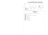
Tools Needed for Assembly Materials
• One Phillips head screwdriver
• One stepladder
• One ¼˝ blade screwdriver
•
9
⁄16˝ Socket head wrench
• One wire stripper
Wire Size A.W.G.Installed Wire Length
14
12
Up to 50 ft.
50 - 100 ft.
NOTE: If you are uncertain of part description, refer to
exploded view illustration. (Figure 1, page 11)
Check to see that you have received the following parts:
• Hardware bag:
– Four wire connectors
– Two
5
/32˝ threaded rods
– Two
5
/32˝ lockwashers
– Two
5
/32˝ knurled knobs
• Support Cable bag:
– Ceiling Support Cable
– Cable Clamp
– ˝ x 2˝ lag bolt
– ˝ fl at washer
• Lower Cover Assembly
• Lower Cap
• C4 Fan & Light Remote Control
• Remote Receiver Unit
Downrod/
Hanger Ball
Assembly
Hanger
Bracket
Lower Cover
Assembly
Ceiling Fan
Assembly
Hardware Bag
Ceiling Canopy
Remote
Receiver
Unit
C4 Remote
Control
• Ceiling Fan assembly
• Downrod/Hanger Ball assembly
• Ceiling Canopy
• Hanger Bracket
• Motor Coupling Cover
Motor Coupling
Cover
▲
WARNING
Do not install or use fan if any part is damaged or
missing. This product is designed to use only those
parts supplied with this product and/or any accessories
designated specifically for use with this product by
Fanimation. Substitution of parts or accessories not
designated for use with this product by Fanimation could
result in personal injury or property damage. Contact
your retail store for missing or damaged parts.
▲
WARNING
Before assembling your ceiling fan, refer to section on
proper method of wiring your fan (page 4). If you feel you
do not have enough wiring knowledge or experience,
have your fan installed by a licensed electrician.
Lower Cap
NOTE: The illustration shown is not to scale or its actual confi guration may vary.
Wires partially removed for clarity.

4
Electrical and Structural Requirements
Your new ceiling fan will require a grounded electrical
supply line of 120 volts AC, 60 Hz, 15 amp circuit. The
outlet box must be securely anchored and capable of
withstanding a load of at least 50 lbs. Figure 1 depicts
different structural confi gurations that may be used for
mounting the outlet box.
If your fan is to replace an existing light fi xture, turn
electricity off at the main fuse box at this time and remove
the existing light fi xture.
1. To prevent damage to housing and/or blade, leave
the Ceiling Fan Assembly in its original packing during
installation of lower cover assembly, down rod, ceiling
canopy and motor coupling cover.
NOTE: Do not set Ceiling Fan Assembly on fl oor or hard
surface.
2. Prior to assembly, set aside and save the hardware
bag(s) packed in the packing.
3. Assemble the Lower Cover Assembly by connecting
the 2-pin (black & white wires) socket connector to
the plug connector (blue & white wires). Be sure the
connector wires are inside the Control Housing before
assembling the Lower Cover Assembly. (Figure 1)
4. Locate and loosen two Indexing Screws located on the
Control Housing. (Figure 1) Line up the indexing holes
over the screws, secure by twisting the Lower Cover
Assembly clockwise and tighten the two indexing screws.
(Figure 2)
5. Turn the Ceiling Fan Assembly (in package) top-side
up for installing down rod, ceiling canopy and motor
coupling cover.
How to Assemble Your Ceiling Fan
Figure 1
Control
Housing
Index Screw (2 places)
2-pin
connector
2˝ x 4˝
Ceiling
Joists
Ceiling
Outlet
Box
Figure 1
▲
WARNING
To avoid fire or shock, follow all wiring instructions
carefully. Any electrical work not described in these
instructions should be done or approved by a licensed
electrician.
▲
WARNING
Turning off wall switch is not sufficent. To avoid
possible electrical shock, be sure electricity is turned
off at the main fuse box before wiring. All wiring must
be in accordance with National and Local codes and the
ceiling fan must be properly grounded as a precaution
against possible electrical shock.
Figure 2
Indexing
Holes
(2 places)
▲
WARNING
To reduce the risk of fire, electrical shock, or personal
injury, mount fan to outlet box marked acceptable
for fan support of 22.7 kg (50 lbs) or less. Use screws
supplied with outlet box. Most outlet boxes commonly
used for support of light fixtures are not acceptable for
fan support and may need to be replaced. Consult a
qualified electrician if in doubt.

5
How to Assemble Your Ceiling Fan (cont’d)
6. Remove the Hanger Ball by loosening the setscrew
in the Hanger Ball until the ball falls freely down the
Downrod. (Figure 3a) Remove the Pin from the
Downrod, then remove the Hanger Ball. Retain the Pin
and Hanger Ball for reinstallation in Step 9.
7. Separate and untwist the three wires and the safety
cable. Route the leads through the Downrod.
8. Loosen the two setscrews in the Downrod Support.
Align the Clevis Pin holes in the Downrod with the holes
in the Downrod Support. Install the Clevis Pin and secure
with the Hairpin Clip. (Figure 3b)
9. Pass the Downrod/Hanger Ball Assembly through the
top of the ceiling canopy and push the bell-shaped motor
coupling cover on to the downrod as shown. (Figure 4)
NOTE: You will be using either the 6” downrod supplied
with your fan or an optional downrod purchased
seperately.
10. Loosen the two setscrews in the downrod support.
Align the clevis pin holes in the downrod with the holes
in the downrod support. Install the clevis pin and secure
with the hairpin clip (Figure 3). The clevis pin must go
through the holes in the downrod support and the holes
in the downrod. Be sure to push the straight leg of the
hairpin clip through the hole near the end of the clevis pin
until the curved portion of the hairpin clip snaps around
the clevis pin. The hairpin clip must be properly installed
to prevent the clevis pin from working loose. Pull on
the hanger ball to make sure the clevis pin is properly
installed.
11. While pulling up on the hanger ball, securely tighten
the two setscrews in the downrod support (Figure 3).
NOTE: The setscrews must be properly installed as
described above, or fan-wobble could result.
12. Slide the motor coupling cover down until it touches
the top of the motor.
13. The fan comes with a support cable, blue, black,
orange and white leads. Before installing fan, measure
up approximately 6-9 inches above top of Downrod/
Hanger Ball Assembly. Cut off excess cable and wire.
Strip back insulation ½” from end of each wire.
Clevis
Pin
Ceiling
Canopy
Motor
Coupling
Cover
Hanger
Ball
Assembly
Downrod
Support
Hairpin
Clip
Setscrew (2)
14. You have now completed the assembly of your new
ceiling fan. You can now proceed with the hanging and
the electrical wiring of your fan.
Figure 3b
Figure 4
▲
WARNING
It is critical that the clevis pin in the downrod support
is properly installed and the setscrews are securely
tightened. Failure to verify that the pin and setscrews
are properly installed could result in the fan falling.
Figure 3a
Setscrew
Pin

Junction
Box
Ceiling
Support
Cable
Ceiling Joist
Wood Member
(2” x 4” Approx.)
Hanger Bracket
Ceiling
Downrod/Hanger
Ball Assembly
Attach
Safety Cable to
Ceiling Support
Cable
Tab
NOTE: Supply wires and
fan wires omitted for clarity
Ceiling
Floor
Ceiling
No
less than
7 ft
Blade Radius 30˝
(60˝ Blade Sweep)
6
How to Hang Your Ceiling Fan
1. Securely attach the ceiling support cable to the ceiling
joist or structural member using the ⅜˝ x 2˝ lag bolt and
fl at washer. The lag bolt will pass through the fl at washer,
loop of the ceiling support cable, the outlet box and into
the supporting member (Figure 2). You will fi rst drill a ¼˝
pilot hole into the supporting member to prevent splitting
or cracking.
2. Securely attach the hanger bracket to ceiling junction
box acceptable for ceiling support.
NOTE: Ceiling support cable cannot be secured to
junction box only, it must be directly secured to ceiling
joist or structural member using the ⅜˝ x 2˝ lag bolt and
fl at washer. (Figure 2).
Figure 3
Figure 2
Figure 1
3. Make sure the electrical supply wires, including the
hanger bracket grounding wire and safety cable are
pulled through the downrod, between the hanger bracket
and the junction box so that electrical connections can be
made later.
4. Carefully lift the fan and seat the downrod/hanger ball
assembly on the hanger bracket that was just attached to
the ceiling joist. Be sure the groove in the ball is lined up
with tab on the hanger bracket. (Figure 3)
5. Attach the safety cable to ceiling support cable. Slide
cable clamp onto safety cable (from fan). Place the end
of cable through the loop of ceiling support cable. Pull as
much cable through loop as possible. Feed end of cable
into clamp hole and fi rmly tighten screw (Figure 3). Cut
off excess safety cable.
INSTALLATION NOTE
If you are installing your ceiling fan on a sloped ceiling,
the hanger bracket must be mounted with the opening
parallel to the slope.
INSTALLATION NOTE
Be sure that the safety cable (along with the electrical
supply wires) is pulled through the downrod when
installing the downrod.
▲
WARNING
Failure to seat tab in groove could cause damage to
electrical wires and possible shock or fire hazard.
▲
WARNING
To avoid possible shock, do not pinch wires between the
downrod/hanger ball assembly and the hanger bracket.
▲
WARNING
The fan must be hung with at least 7´ of clearance from
floor to blade (Figure 1)
▲
WARNING
To avoid possible electrical shock, be sure electricity is
turned off at the main fuse box before hanging.
NOTE: If you are not sure if the outlet box is grounded,
contact a licensed electrician for advice, as it must be
grounded for safe operation.

OFF
HI
LO
MED
9V
Battery
Remote Transmitter
Unit Detail
Reciever Unit Detail
9V
Battery
Receiver Unit
Ceiling
Bracket
(Open End)
NOTE: Receiver wires omitted for clarity.
BLK-ANT
BL-AC IN L
WH-AC IN N
BLUE-FOR LIGHT DOWN
BLK-TO MOTOR L
WH-TO MOTOR N
GRN or BARE GROUND
GRN from hanger ball
GRN from bracket
120 VAC SUPPLY
(User Supplied)
7
How to Wire Your Ceiling Fan - C4 Remote Control
Operating Instructions - C4 Remote Control
1. Operating & Using Remote Transmitter (Figure 1):
Install 9 volt battery (If not using for long periods of time,
remove battery to prevent damage to transmitter). Store
the transmitter away from excess heat or humidity.
1. Setting the Code: The remote unit has 16 different
code combinations. To prevent possible interference from
or to other remote units such as garage door openers, car
alarm or security systems, simply change the combination
code in your transmitter and receiver. To set the code,
perform these steps.
• Transmitter: remove battery cover. Press firmly below
arrow and slide battery cover off. Slide code switches to
your choice of up or down position. Factory setting is all
up. Do not use this position. With a small screwdriver or
ball point pen slide firmly up or down (Figure 1a). Replace
battery cover on the transmitter.
• Receiver: Slide code switches to the same positions
as set on your transmitter (Figure 1b).
If you feel that you do not have enough electrical wiring
knowledge or experience, have your fan installed by a
licensed electrician.
2. Installing Receiver in Hanger Bracket:
• Slide remote Receiver into the Hanger Bracket
(Figure 2).
• Connect wires as indicated: (Figure 3)
– Green Hanger Bracket and Hanger Ball wires to
BARE (ground) wire.
– BLACK Receiver Unit wire (AC IN L) to BLACK
supply wire.
– WHITE Receiver Unit wire (AC IN N). to WHITE
supply wire.
– WHITE Receiver Unit wire (TO MOTOR N) to WHITE
fan wire.
– BLACK Receiver Unit wire (TO MOTOR L) to BLACK
fan wire.
– BLUE Receiver Unit wire (FOR LIGHT DOWN) to
BLUE light wire.
• Position all connected wires and receiver antenna to
allow installation of ceiling canopy.
• To install ceiling canopy, see page 8.
• Restore electrical power.
NOTE: If fan or supply wires are different colors than indicated,
have this unit installed by a qualifi ed electrician.
• HI Push Button – high fan speed
• MED Push Button – medium fan speed
• LOW Push Button – low fan speed
• OFF Push Button – fan off
• Light Push Button – no function (unless light bulb is
installed)
Figure 2
Figure 3
Figure 1bFigure 1a
Figure 1
▲
WARNING
Check to see that all connections are tight, including
ground, and that no bare wire is visible at the wire
connectors, except for the ground wire. Do not operate
fan until the blades is in place. Noise and fan damage
could result.
▲
WARNING
To avoid possible electrical shock, be sure electricity is
turned off at the main fuse box before wiring.
NOTE: If you are not sure if the outlet box is grounded,
contact a licensed electrician for advice, as it must be
grounded for safe operation.

8
Installing the Canopy Housing
1. Screw in two threaded rods into the Hanger Bracket
(Figure 1a).
NOTE: The threaded rods in the hanger bracket serves
as guides for easier installation.
2. Securely attach the Canopy Housing to the Hanger
Bracket using the external lockwashers and knurled
knobs supplied with your fan (Figure 1b)
Figure 1a
Final Assembly - Options
1. Carefully screw the bulb in the socket fi rmly.
2. Restore power.
Figure 1
NOTE: This step is applicable after the neccessary
wiring is completed. (see page 7)
NOTE: Supply wires and fan wires omitted for clarity
1. To install lower cap - screw in lower cap into bulb
socket until tight. (Figure 3)
3. Restore power.
Figure 2
▲
WARNING
To avoid possible fire or shock, make sure that the
electrical wires are completely inside the canopy housing
and not pinched between the housing and the ceiling.
▲
WARNING
To prevent over-heating or electrical fi res, use ONLY
PAR30, short-neck halogen bulb, 75 watt max, as
specifi ed (bulb not included).
▲
WARNING
Do NOT install lower cap while the ceiling fan is on!
Figure 1b
Light Bulb Option:
Lower Cap Option:
CAUTION
To avoid possible electrical shock, be sure electricity
is turned off at the main fuse box before installing light
bulb.

9
Maintenance
Periodic cleaning of your new ceiling fan is the only
maintenance that is needed. When cleaning, use only a
soft brush or lint free cloth to avoid scratching the fi nish.
Abrasive and/or non-abrasive cleaning agents are not
required and should be avoided to prevent damage to
fi nish.
CAUTION
Do not use water when cleaning your ceiling fan. It could
damage the motor or the finish and create the possibility
of electrical shock.
Trouble Shooting
▲
WARNING
For your own safety turn off power at fuse box or circuit breaker before trouble shooting your fan.
Trouble Probable Cause Suggested Remedy
1. FAN WILL NOT START
1. Fuse or circuit breaker blown.
2. Loose power line connections to the fan, or loose
switch wire connections in the switch housing.
3. Dead battery in remote control.
1. Check main and branch circuit fuses or circuit
breakers.
2. Check line wire connections to fan and switch wire
connections in the switch housings.
CAUTION: Make sure main power is turned off !
3. Replace with fresh battery.
2. FAN SOUNDS NOISY
1. Motor noise caused by solid state variable speed
control.
1. Some fan motors are sensitive to signals from
solid-state variable speed controls. Solid-state controls
are not recommended, choose an alternative control
method.
3. FAN WOBBLES
EXCESSIVELY
1. Setscrew in downrod support is loose.
2. Setscrew in downrod/hanger ball assembly is loose.
3. Hanger bracket and/or ceiling outlet box is not
securely fastened.
1. Tighten both setscrews securely in downrod support.
2. Tighten the setscrew in the downrod/hanger ball
assembly.
3. Tighten the hanger bracket screws to the outlet box,
and secure outlet box.

10
Ref. # Description Part #
1 Hanger Bracket APG610BL
5 Ceiling Canopy
P2100
¾¾
2 Downrod/Hanger Ball Assembly Containing:
ADR1x6
¾¾
2a Hanger Ball Assembly
2b Downrod
2c Clevis Pin
2d Hairpin Clip
3 Ceiling Canopy
PG158
¾¾
4 Motor Coupling Cover
AP60030
¾¾
5 Ceiling Fan Assembly
AMA2120
¾¾
6 Lower Cover Assembly
AP2101
¾¾
7 Lower Cap
P2120
¾¾
8
Hardware Bag Containing:
HDWFP2120
5/32˝ Threaded Rods (2)
5/32˝ External Lockwashers (2)
Knurled Knobs (2)
Wire Connectors (3)
Support Cable Bag Containing:
HWBSCABLE
Ceiling Support Cable
Cable Clamp
Flat Washer
⅜˝ x 2˝ Lag Bolt
9 Receiver Unit RECAN34
10 Remote Control C4
Before discarding packaging materials, be certain all parts have been removed
Parts List
¾¾
Insert FINISH CODES (Refer to fan model number located on downrod support)
Model #FP2120
¾¾
How To Order Parts
When ordering repair parts, always
give the following information:
• Part Number
• Part Description
• Fan Model Number
Contact your retail store for repair parts.

2a
2b
2c
2d
2
8
7
6
4
5
3
9
1
10
11
NOTE: The illustration shown is not to scale or its actual confi guration may vary.
Wires partially removed for clarity.
Exploded-View
The Enigma
®
FP2120**
Figure 1

10983 Bennett Parkway
Zionsville, IN 46077
(888) 567-2055
FAX (866) 482-5215
Visit Our Website @ www.fanimation.comCopyright 2007 Fanimation 2007/08
-
 1
1
-
 2
2
-
 3
3
-
 4
4
-
 5
5
-
 6
6
-
 7
7
-
 8
8
-
 9
9
-
 10
10
-
 11
11
-
 12
12


Fanimation Limited Edition Cust Owner's manual
- Category
- Household fans
- Type
- Owner's manual
Ask a question and I''ll find the answer in the document
Finding information in a document is now easier with AI
Related papers
-
Fanimation Subtle FPD6236 User manual
-
-
-
-
-
-
Fanimation Draco Owner's manual
-
-
Fanimation Hubbardton Forge HF6000-Std Owner's manual
-
 Fanimation Studio Collection LP8069 AireDrop WiFi Owner's manual

Other documents
-
Yosemite Home Decor LK498AP User guide
-
 Fanimation Studio Collection LP8350BLAZ Installation guide
-
 Fanimation Studio Collection LP7678LBN Installation guide
-
AireRyder X-WC4015 User guide
-
 AirFiciency CF60E User manual
-
 Volume Lighting V4155-65 Operating instructions
-
Illumine CLI-EMM018046 Installation guide
-
-
Electrolux CF921BS00 User manual
-
Emerson CF100GES00 User manual


