Page is loading ...

USERʼS MANUAL
www.nordictrack.com
Serial Number Decal (Under Seat)
Model No. 30281.0
Serial No.
Write the serial number in the
space above for reference.
QUESTIONS?
If you have questions, or if parts
are damaged or missing, PLEASE
CONTACT OUR CUSTOMER
SERVICE DEPARTMENT
DIRECTLY.
CALL TOLL-FREE:
1-888-936-4266
Mon.–Fri., 8:00 until 17:00 ET
(excluding holidays)
OR E-MAIL US:
CAUTION
Read all precautions and instruc-
tions in this manual before using
this equipment. Keep this manual
for future reference.

WARNING DECAL PLACEMENT
2
NordicTrack is a registered trademark of ICON IP, Inc.
TABLE OF CONTENTS
WARNING DECAL PLACEMENT . . . . . . . . . . . . . . . . . . . . . . . . . . . . . . . . . . . . . . . . . . . . . . . . . . . . . . . . . . . . . .2
I
MPORTANT PRECAUTIONS . . . . . . . . . . . . . . . . . . . . . . . . . . . . . . . . . . . . . . . . . . . . . . . . . . . . . . . . . . . . . . . .3
BEFORE YOU BEGIN . . . . . . . . . . . . . . . . . . . . . . . . . . . . . . . . . . . . . . . . . . . . . . . . . . . . . . . . . . . . . . . . . . . . . .4
PART IDENTIFICATION CHART . . . . . . . . . . . . . . . . . . . . . . . . . . . . . . . . . . . . . . . . . . . . . . . . . . . . . . . . . . . . . .5
ASSEMBLY . . . . . . . . . . . . . . . . . . . . . . . . . . . . . . . . . . . . . . . . . . . . . . . . . . . . . . . . . . . . . . . . . . . . . . . . . . . . . . .6
ADJUSTMENT . . . . . . . . . . . . . . . . . . . . . . . . . . . . . . . . . . . . . . . . . . . . . . . . . . . . . . . . . . . . . . . . . . . . . . . . . . .15
WEIGHT RESISTANCE CHART . . . . . . . . . . . . . . . . . . . . . . . . . . . . . . . . . . . . . . . . . . . . . . . . . . . . . . . . . . . . . .20
CABLE DIAGRAM . . . . . . . . . . . . . . . . . . . . . . . . . . . . . . . . . . . . . . . . . . . . . . . . . . . . . . . . . . . . . . . . . . . . . . . . .21
EXERCISE GUIDELINES . . . . . . . . . . . . . . . . . . . . . . . . . . . . . . . . . . . . . . . . . . . . . . . . . . . . . . . . . . . . . . . . . . .22
PART LIST . . . . . . . . . . . . . . . . . . . . . . . . . . . . . . . . . . . . . . . . . . . . . . . . . . . . . . . . . . . . . . . . . . . . . . . . . . . . . .24
EXPLODED DRAWING . . . . . . . . . . . . . . . . . . . . . . . . . . . . . . . . . . . . . . . . . . . . . . . . . . . . . . . . . . . . . . . . . . . .26
ORDERING REPLACEMENT PARTS . . . . . . . . . . . . . . . . . . . . . . . . . . . . . . . . . . . . . . . . . . . . . . . . . .Back Cover
LIMITED WARRANTY . . . . . . . . . . . . . . . . . . . . . . . . . . . . . . . . . . . . . . . . . . . . . . . . . . . . . . . . . . . . . . Back Cover
ATTENTION
Part # 166295
This drawing shows the location(s) of the warning
decal(s). If a decal is missing or illegible, see
the front cover of this manual and request a
free replacement decal. Apply the decal in the
location shown. Note: The decal(s) may not be
shown at actual size.

3
WARNING: To reduce the risk of serious injury, read all important precautions and
instructions in this manual and all warnings on your weight system before using your weight sys-
tem. ICON assumes no responsibility for personal injury or property damage sustained by or
t
hrough the use of this product.
IMPORTANT PRECAUTIONS
1. Before beginning any exercise program,
consult your physician. This is especially
important for persons over the age of 35 or
persons with pre-existing health problems.
2. It is the responsibility of the owner to
ensure that all users of the weight system
are adequately informed of all precautions.
3. The weight system is intended for home use
only. Do not use the weight system in any
commercial, rental, or institutional setting.
4. Keep the weight system indoors, away from
moisture and dust. Place the weight system
on a level surface, with a mat beneath it to
protect the floor or carpet. Make sure that
there is enough clearance around the weight
system to mount, dismount, and use the
weight system.
5. Inspect and properly tighten all parts regu-
larly. Replace any worn parts immediately.
6. Keep children under 12 and pets away from
the weight system at all times.
7. Keep hands and feet away from moving
parts.
8. Always wear athletic shoes for foot protec-
tion while exercising.
9. The weight system is designed to support a
maximum user weight of 300 lbs. (136 kg).
10. Make sure that the cables remain on the pul-
leys at all times. If the cables bind as you
are exercising, stop immediately and make
sure that the cables are on the pulleys.
11. Always stand on the base plate when per-
forming an exercise that could cause the
weight system to tip.
12. Never release the handles, leg lever, squat
bar, ankle strap, or curl bar while weights
are raised; the weights will fall with great
force.
13. Do not use the weight system with the top
weight pinned in an elevated position.
14. Use the weight system only with the includ-
ed weight. Do not use the weight system
with any other type of weight to add resist-
ance.
15. Always secure the weight stack with the
lock pin and lock after exercising to prevent
unauthorized use of the weight system (see
LOCKING THE WEIGHT STACK on page 19).
16.
Always make sure that the pins and knobs
are fully engaged before you use the
weight system.
17.
Over exercising may result in serious injury
or death. If you feel faint or if you experi-
ence pain while exercising, stop immediately
and cool down.

4
Weight Pin
Press Arm
Dip Handle
Dip Arm Knob
Dip Arm
Dip Arm Pin
Press Arm Knob
Backrest
Handle
Extension
Strap
Right Side
Left Side
Note: The terms “right side” and “left side” are determined relative to a person sitting on the
seat; they do not correspond to right and left on the drawings in the manual.
Weight
Locking Caster
Leg Developer
Seat
Pulley Housing
Base
Squat Bar
Curl Pad
Curl Bar
Ankle Strap
BEFORE YOU BEGIN
T
hank you for selecting the versatile NordicTrack
®
3
60°
WITH FREEMOTION TECHNOLOGY weight system.
The weight system offers a selection of weight stations
designed to develop every major muscle group of the
b
ody. Whether your goal is to tone your body, build
dramatic muscle size and strength, or improve your
cardiovascular system, the weight system will help you
to achieve the specific results you want.
For your benefit, read this manual carefully before
using the weight system. If you have questions after
r
eading this manual, please see the front cover of this
manual. To help us assist you, note the product model
number and serial number before contacting us. The
model number and the location of the serial number
d
ecal are shown on the front cover of this manual.
Before reading further, please familiarize yourself with
the parts that are labeled in the drawing below.
ASSEMBLED DIMENSIONS:
Height: 7 ft. 1 in. (216 cm)
Width: 6 ft. 3 in. (191 cm)
Depth: 5 ft. 1 in. (155 cm)
Weight: 150 lbs. (68 kg)

M6 Washer (107)
M10 Washer (105)
M8 Locknut (110)
M10 Locknut (108)
M10 x 55mm Carriage Bolt (83)
M8 x 20mm Button
Bolt (92)
M8 x 65mm Button Bolt (94)
M6 x 85mm Screw (85)
M6 x 100mm Screw (113)
M6 x 70mm Screw (93)
M4 x 16mm Self-tapping Screw (99)
M4 x 19mm Self-tapping
Screw (100)
M4 x 13mm Self-tapping Screw (112)
M3 x 32mm Self-tapping
Screw (102)
M10 x 50mm Button Bolt (88)
M10 x 100mm Button Bolt (91)
M10 x 115mm Bolt (84)
M10 x 75mm Bolt (86)
M10 x 65mm Bolt (95)
M10 x 50mm Bolt (96)
M10 x 40mm Screw (97)
M6 x 16mm Screw (87)
M6 x 10mm Set Screw (114)
PART IDENTIFICATION CHART
R
efer to the drawings below to identify small parts used in assembly. The number in parentheses by each draw-
ing is the key number of the part, from the PART LIST near the end of this manual. Note: If a part is not in the
hardware kit, check to see if it has been preattached.
5

6
1.
Attach a Wheel (32) to a Wheel Cap (31) with
an M8 x 65mm Button Bolt (94) and an M8
Locknut (110). Do not overtighten the
Locknut; the Wheel must pivot easily.
Attach the Wheel Cap (31) to the Base (1) with
two M4 x 16mm Self-tapping Screws (99).
Repeat this step with the other Wheel Cap
(31).
2. Attach a Locking Caster (76) to the Base (1)
with four M8 x 20mm Button Bolts (92) and four
M8 Locknuts (110).
Repeat this step with the other Locking
Caster (76).
1
2
32
31
99
94
99
110
31
92
1
92
76
110
110
76
1
ASSEMBLY
To make assembly easier, carefully read the
following information and instructions:
• Assembly requires two persons.
• Because of its weight and size, the weight system
should be assembled in the location where it will
be used. Make sure that there is enough clear-
ance to walk around the weight system as you
assemble it.
• Place all parts in a cleared area and remove the
packing materials. Do not dispose of the packing
materials until assembly is completed.
• For help identifying small parts, use the PART
IDENTIFICATION CHART on page 5.
• The following tools (not included) may be required
for assembly:
two adjustable wrenches
o
ne rubber mallet
one standard screwdriver
one Phillips screwdriver
clear tape or masking tape, and soapy water
Assembly may be more convenient if you have a
socket set, a set of open-end or closed-end
wrenches, or a set of ratchet wrenches.
To make assembly easier, read the
information on page 5 before you begin.

22
EXERCISE GUIDELINES
FOUR TYPES OF STRENGTH WORKOUTS
Note: A “repetition” is one complete cycle of an exer-
cise, such as one sit-up. A “set” is a series of repeti-
tions.
Muscle Building—Work your muscles near their max-
imum capacity and progressively increase the intensity
of your exercise. Adjust the intensity level of an individ-
ual exercise as follows:
• Change the amount of resistance used.
• Change the number of repetitions or sets performed.
Use your own judgment to determine the amount of
resistance that is right for you. Begin with 3 sets of 8
repetitions for each exercise you perform. Rest for 3
minutes after each set. When you can complete 3 sets
of 12 repetitions without difficulty, increase the amount
of resistance.
Toning—Tone your muscles by working them to a
moderate percentage of their capacity. Select a mod-
erate amount of resistance and increase the number
of repetitions in each set. Complete as many sets of
15 to 20 repetitions as possible without discomfort.
Rest for 1 minute after each set. Work your muscles
by completing more sets rather than by using high
amounts of resistance.
Weight Loss—To lose weight, use a low amount of
resistance and increase the number of repetitions in
each set. Exercise for 20 to 30 minutes, resting for a
maximum of 30 seconds between sets.
Cross Training—Combine strength training and aero-
bic exercise by following this type of program:
• Strength workouts on Monday, Wednesday, and
Friday.
• 20 to 30 minutes of aerobic exercise on Tuesday
and Thursday.
• One full day of rest each week to give your body
time to regenerate.
WORKOUT GUIDELINES
Familiarize yourself with the equipment and learn the
proper form for each exercise. Use your own judgment
to determine the appropriate length of time for each
workout, and the numbers of repetitions and sets to
c
omplete. Progress at your own pace and be sensitive
to your bodyʼs signals. Follow each strength workout
with at least one day of rest.
Warming Up—Start with 5 to 10 minutes of stretching
and light exercise. A warm-up increases your body
temperature, heart rate, and circulation in preparation
for exercise.
Working Out—Include 6 to 10 different exercises in
each workout. Select exercises for every major muscle
group, emphasizing areas that you want to develop. To
give balance and variety to your workouts, vary the
exercises from workout to workout.
Cooling Down—Finish with 5 to 10 minutes of
stretching. Stretching increases the flexibility of your
muscles and helps to prevent post-exercise problems.
EXERCISE FORM
Move through the full range of motion for each exer-
cise and move only the appropriate parts of the body.
Perform the repetitions in each set smoothly and with-
out pausing. The exertion stage of each repetition
should last about half as long as the return stage.
Exhale during the exertion stage of each repetition and
inhale during the return stroke. Never hold your
breath.
Rest for a short period of time after each set:
• Muscle Building—Rest for three minutes after each
set.
• Toning—Rest for one minute after each set.
• Weight Loss—Rest for 30 seconds after each set.
STAYING MOTIVATED
For motivation, keep a record of each workout. Write
the date, the exercises performed, the resistance
used, and the numbers of sets and repetitions com-
pleted. Record your weight and key body measure-
ments once a month. To achieve good results, make
exercise a regular and enjoyable part of your life.

21
CABLE DIAGRAM
T
he cable diagram shows the proper routing of the
Press Arm Cable (66). Use the diagram to make
sure that the cable and the cable traps have been
assembled correctly. If the cable has not been cor-
r
ectly routed, the weight system will not function
properly and damage may occur. The numbers
show the correct route for the cable. Make sure
that the cable traps do not touch or bind the
cable.
13
6
7
9
2
10
4
5
Press Arm Cable (66)
1
12
3
11
8

9
6. See drawing 6b. Attach the Front Shroud (14)
t
o the Base (1) with an M4 x 16mm Self-tapping
Screw (99).
See drawing 6a. Note: If the Press Arm
Cable (not shown) has been routed through
the Top Cover (24), make sure that the Cable
c
rosses under the Top Frame (12) and
hangs between the Weight Guides (13, 36)
while this step is completed.
Attach the Top Frame (12) to the Weight Guides
(13, 36) with two M10 x 65mm Bolts (95), four
M10 Washers (105), two 16mm x 6mm Spacers
(11), and two M10 Locknuts (108). Do not
tighten the Locknuts yet.
Attach the Top Frame (12) to the Upright (3)
with two M10 x 100mm Button Bolts (91) and
an M10 Locknut (108).
Set the Top Cover (24) over the Front Shroud
(14) and the Top Frame (12).
See steps 3 and 6. Tighten the M10 Locknuts
(108) used in steps 3 and 6.
1
2
95
1
05
108
6a
6b
99
14
1
14
3
11
108
105
105
13
36
24
91
7. See the CABLE DIAGRAM on page 21 to
ensure correct cable routing during steps 7
through 14.
Use the wire in the Left Press Arm (7) to pull
the Press Arm Cable (66) up through the Press
Arm. Make sure that the Cable is routed
around the pulleys above the Press Arm as
shown in the inset drawing.
Hold a 4" Pulley (42) over the Press Arm Cable
(66). Attach the Pulley inside of the Swivel Arm
(26) with an M10 x 50mm Button Bolt (88), two
M10 Washers (105), two 16mm x 6mm Spacers
(11), and an M10 Locknut (108).
7
7
11
11
88
105
105
108
42
66
26
66

10
9. Route the Press Arm Cable (66) through the
Top Cover (24) and over a 3 1/2" Pulley (43).
Attach the Pulley and a Cable Trap (47) to the
Top Frame (12) with an M10 x 40mm Screw
(97). Make sure that the Cable Trap is orient-
ed to hold the Cable in the groove of the
Pulley.
10. Route the Press Arm Cable (66) under a 3 1/2"
Pulley (43). Attach the Pulley, a Cable Trap
(47), and two Finger Guards (48) to the second
hole from the top of the Weight Tube (16) with
an M10 x 50mm Bolt (96) and an M10 Locknut
(108). Make sure that the Cable Trap is ori-
ented to hold the Cable in the groove of the
Pulley.
8. Route the Press Arm Cable (66) over a 3 1/2"
Pulley (43). Attach the Pulley and a Cable Trap
(47) to the Top Frame (12) with an M10 x 40mm
S
crew (97). Make sure that the Cable Trap is
oriented to hold the Cable in the groove of
t
he Pulley.
12
8
9
24
66
66
16
48
48
47
96
108
12
66
47
4
3
43
43
97
47
97
10

11
13. Use the wire in the Right Press Arm (8) to pull
the Press Arm Cable (66) down through the
Press Arm. Make sure that the Cable is rout-
ed around the pulleys above the Press Arm
as shown in the inset drawing.
Hold a 4" Pulley (42) over the Press Arm Cable
(66). Attach the Pulley inside of the Swivel Arm
(26) with an M10 x 50mm Button Bolt (88), two
M10 Washers (105), two 16mm x 6mm Spacers
(11), and an M10 Locknut (108).
12. Route the Press Arm Cable (66) through the
Top Cover (24) and over a 3 1/2" Pulley (43).
Attach the Pulley and a Cable Trap (47) to the
Top Frame (12) with an M10 x 40mm Screw
(97). Make sure that the Cable Trap is orient-
ed to hold the Cable in the groove of the
Pulley.
12
12
43
24
47
97
66
88
105
13
105
108
66
8
66
42
11
11
26
11. Route the Press Arm Cable (66) over a 3 1/2"
Pulley (43). Attach the Pulley and a Cable Trap
(47) to the Top Frame (12) with an M10 x 40mm
S
crew (97). Make sure that the Cable Trap is
oriented to hold the Cable in the groove of
t
he Pulley.
12
66
43
11
47
97

12
14. Orient the Cable Cover (63) as shown and slide
it onto the Press Arm Cable (66).
I
nsert the Press Arm Cable (66) into the Cable
Coupler (64) as far as possible. Firmly tighten
f
our M6 x 10mm Set Screws (114) into the
Coupler to hold the Cable in place.
Slide the Cable Cover (63) over the Cable
Coupler (64).
14
66
63
6
4
114
114
15. See drawing 15a. Slide the Rear Shroud (15)
under the Top Cover (24).
Attach the Top Cover (24) and the Front and
Rear Shrouds (14, 15) to the Top Frame (12)
with three M4 x 16mm Self-tapping Screws
(99).
See drawing 15b. Attach the Rear Shroud (15)
to the Base (1) with an M4 x 16mm Self-tapping
Screw (99).
99
99
12
14
15
24
15a
15b
99
15
1
16. Attach the Backrest (18) to the Upright (3) with
two M6 x 100mm Screws (113) and two M6
Washers (107).
16
18
3
107
107
113
113

13
18. Attach the Bumper (115) to the Leg Developer
(6) with an M4 x 19mm Self-tapping Screw
(100).
Apply grease to an M10 x 75mm Bolt (86).
Attach the Leg Developer (6) to the Seat Frame
(4) with the Bolt and an M10 Locknut (108). Do
not overtighten the Locknut; the Leg
Developer must pivot easily.
17. Attach the Seat (19) to the Seat Frame (4) with
two M6 x 16mm Screws (87) and an M6 x
85mm Screw (85).
Set the Seat Frame (4) onto a set of posts on
t
he Upright (3).
17
19
4
85
87
18
86
Grease
4
108
100
115
6
33
10
34
35
51
102
102
5
19. Attach a Front and Rear Dip Cap (33, 34)
around a Dip Handle (10) with two M3 x 32mm
Self-tapping Screws (102).
Tighten a Dip Arm Knob (51) into the Dip Arm
(5). Pull the Dip Arm Knob out as far as it will
go, and insert the Dip Handle (10) through a
Dip Arm Bushing (35) and into the Dip Arm.
Then, engage the Dip Arm Knob into the Dip
Handle.
Repeat this step on the other side of the Dip
Arm (5).
19

14
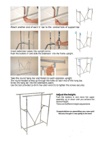
22. Attach the Curl Pad (20) to the Curl Post (9)
with two M6 x 16mm Screws (87).
23. Make sure that all parts are properly tightened before you use the weight system. The use of the remaining
parts will be explained in the ADJUSTMENT section, beginning on page 15.
21. Insert a Pad Tube (17) into the Leg Developer
(6). Slide two Leg Pads (23) onto the Pad Tube.
Slide two Leg Pads (23) onto the Seat Frame
(4).
21
6
4
17
23
23
23
23
20
9
87
22
20. Attach an Arm Pad (21) and an Arm Pad Base
(22) to the Dip Arm (5) with two M6 x 70mm
Screws (93).
Repeat this step on the other side of the Dip
A
rm (5).
20
2
1
2
2
93
5

15
This section explains how to adjust the weight system. See the EXERCISE GUIDELINES on page 22 for impor-
tant information about how to get the most benefit from your exercise program. Also, refer to the accompanying
exercise guide to see the correct form for each exercise.
Properly tighten all parts each time the weight system is used. Replace any worn parts immediately. The weight
s
ystem can be cleaned with a damp cloth and a mild, non-abrasive detergent. Do not use solvents.
ADJUSTING THE DIP HANDLES
The Dip Handles (10) can be moved to three differ-
ent lengths in the Dip Arm (5), and rotated in 90-
degree increments.
To adjust a Dip Handle (10), disengage the Dip Arm
Knob (51) and move the Dip Handle to the desired
position. Then, reengage the Dip Arm Knob into the
Dip Handle.
10
8
7
50
25
51
5
10
ADJUSTING THE PRESS ARM
To adjust a Press Arm (7 or 8), first disengage the
Press Arm Knob (50). Move the Press Arm to the
desired position, and reengage the Press Arm Knob
into the Adjustment Plate (25).
WARNING: Always make sure
that the Press Arm Knob (50) fully engages
the Adjustment Plate (25) before you exer-
cise.
ADJUSTMENT

16
53
ADJUSTING THE DIP ARM
To adjust the Dip Arm (5), first make sure that the
p
ress arms are in the lowered position (see
ADJUSTING THE PRESS ARM on page 15). Then,
r
emove the Dip Arm Pin (53). Move the Dip Arm to
the raised or lowered position. Reengage the Dip
Arm Pin into the Upright (3) and the Dip Arm.
3
5
ADJUSTING THE SEAT
To adjust the height of the Seat (19), lift the Seat
Frame (4) off the Upright (3). Set the Seat Frame
onto a different set of posts on the Upright.
For some exercises, the Seat (19) should be
removed from the weight system and stored where
it will not interfere with the exercises.
3
19
4
4
20
9
52
ATTACHING THE CURL PAD
To use the Curl Pad (20), insert the Curl Post (9)
into the Seat Frame (4). Secure the Curl Post with
the Curl Knob (52).
Store the Curl Pad (20) away from the weight sys-
tem while performing exercises that do not require
it.

17
1
3
71
61
6
Squat
ATTACHING THE PULLEY HOUSINGS
The Pulley Housings (54) can be attached to the
U
pright (3) (leg developer position) or to the Base
(1) (squat position or preacher curl position).
To attach a Pulley Housing (54), slide the hook on
the Pulley Housing onto the bracket at the desired
position. Attach the Housing Cable (71) to the
Eyehook (65) with a Clip (61).
ATTACHING THE LEG DEVELOPER
To use the Leg Developer (6), first move the press
arms to the lowered position (see ADJUSTING THE
PRESS ARM on page 15). Next, attach the pulley
housings to the leg developer position (see
ATTACHING THE PULLEY HOUSINGS above).
Then, attach the Housing Cables (71) to the Leg
Developer using a Clip (61).
54
61
65
71
Leg
Developer
Preacher
Curl
6
58
ATTACHING THE CURL BAR
To use the Curl Bar (58), first attach the curl pad to
the seat frame (see ATTACHING THE CURL PAD
on page 16). Next, attach the pulley housings to the
preacher curl position (see ATTACHING THE PUL-
LEY HOUSINGS above). Then, attach the Housing
Cables (71) to the Leg Developer (6) with two Clips
(not shown). Finally, attach the Curl Bar to the Leg
Developer with a Clip (61).
61
71

18
65
69
ATTACHING THE HANDLES
A Handle (69) can be attached to an Eyehook (65),
or to a Housing Cable (not shown), with a Clip (61).
For some exercises, an Extension Strap (not
shown) should be attached between the Eyehook
or the Cable and the Handle with two Clips. Adjust
the Extension Strap to the correct length.
The Ankle Strap (not shown) can be attached in the
same manner.
61
61
71
70
55
ATTACHING THE SQUAT BAR
To use the Squat Bar (55), first remove the seat
(
see ADJUSTING THE SEAT on page 16). Then,
attach the pulley housings to the squat positions
(
see ATTACHING THE PULLEY HOUSINGS on
page 17). Next, attach the Squat Bar to the
Housing Cables (71) with four Clips (61) and the
two Extension Straps (70). Finally, adjust the
Extension Straps to the correct length.
61
76
Lever
MOVING THE WEIGHT SYSTEM
To move the weight system, step on the levers on
the Locking Casters (76) to unlock the wheels.
Move the weight system to the new location. Then,
relock the wheels on the Locking Casters.

19
28
27
CHANGING THE WEIGHT SETTING
To change the setting of the weight stack, insert the
W
eight Pin (28) under the desired Weight (27).
Insert the Weight Pin so that the bent end touches
t
he weight stack. Turn the bent end down.
Note: Due to the cables and pulleys, the amount
of resistance at each exercise station may vary
from the weight setting. Use the WEIGHT
RESISTANCE CHART on page 20 to find the
approximate amount of resistance.
78
77
36
48
66
48
43
47
16
96
108
LOCKING THE WEIGHT STACK
To lock the weight stack, insert the Lock Pin (78)
into the indicated hole in a Weight Guide With Hole
(36). Insert the Lock (77) through the hole in the
Weight Pin and close the Lock.
ADJUSTING THE CABLE
Woven cable, the type of cable used on the weight
system, can stretch slightly when it is first used. If
there is slack in the cable before resistance is felt,
the cables should be tightened.
To tighten the cable, remove the M10 x 50mm Bolt
(96) from the Weight Tube (16). Reattach the 3 1/2"
Pulley (43), the Cable Trap (47), and the two Finger
Guards (48) to a lower hole in the Weight Tube with
the Bolt and an M10 Locknut (108). Make sure that
the Cable Trap is oriented to hold the Press Arm
Cable (66) in the groove of the Pulley. To loosen
the Cable, attach the Pulley to a higher hole in the
Weight Tube.

20
WEIGHT RESISTANCE CHART
T
he chart below shows the approximate weight resistance for the 10-lb. weights. Note: The actual resistance
at each station may vary due to differences in individual weight plates and to friction between the
cables, pulleys, and weight guides.
WEIGHT 1 2 3 4 5 6 7 8 9 10 11 12 13 14 15
Press
Arm*
9 15 20 25 30 36 41 46 51 57 62 67 72 77 84
Leg
Developer
20 30 42 50 65 73 92 97 108 125 137 144 159 170 180
*Weight resistance shown is for each arm.
/