Altec Lansing 1570B Operating instructions
- Type
- Operating instructions

1570B
AMPLIFIER
OPERATING
INSTRUCTIONS
SPECIFICATIONS
Type: Power Amplifier
Gain: 72 db
Input Sensitivity: 1.0 volt rms for rated output
Power Output: 175 watts at less than 5% thd, 65-20,000 cps
165 watts at less than 3% thd, 70-10,000 cps
Frequency Response: ± 1.0 db, 10-50,000 cps
Input Impedance: 70,000 ohm potentiometer
Source Impedance: 150, 600 ohms with 15095 Plug-in Transformer
Load Impedance: 8 (35v), 16 (50 v), 32 (70 v) ohms
Output Impedance: Less than 10% of nominal load impedance
Noise Level: Output noise -25 dbm: 77 db below rated output
Controls: Volume control, continuously variable composition
Power Supply: 105-130 volts, 60 cps, 350 watts
Tubes: 1-12AX7,1-6SN7GTB, 2-6W6GT, 2-811-A, 4-5R4GY
Dimensions: 10 1/2" H, 19" W, 13 1/2" D
Color: Green
Weight: 59 lbs.
Accessories: 15095 Plug-in Transformer
10399 Panel
1515 S. Manchester Ave., Anaheim, Calif.
New York
12969-1
LITHO IN U.S.A.
PRICE $ .14
11/65

GENERAL DESCRIPTION
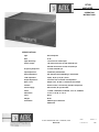
The 1570B Amplifier is a compact, high quality, 165 watt power amplifier designed for public address applications, either
shelf or rack mount. Rack mounting occupies six units (IO1/2") of rack space. Negative feedback is carried around all stages
from a tertiary winding on the heavy duty output transformer, permitting the output to feed an ungrounded load or a load
with one side grounded. This amplifier is designed for stable 70 volt line operation under all output load conditions without
impairment of program quality. Power switch, pilot light and gain control are located on the front of the amplifier and the
input and output terminals, in the form of barrier type terminal blocks, are mounted on the rear. A six-foot three-wire power
cord, terminating in a three-pin cap, is standard equipment with this amplifier.
A special protective device is incorporated in the 1570B in the form of a thermal circuit breaker shunted by a power resistor,
the combination being in series with one side of the power transformer primary. The breaker is fastened to the amplifier
chassis so that heat from the latter is transferred to the breaker thermal element. AC line current through the breaker also
heats the thermal element. Abnormal heating of the chassis and abnormal line current will make the breaker contacts open,
inserting the power resistor in series with the power transformer primary reducing the voltage to it. Program service is thus
maintained at reduced power. The breaker being an automatic reset type, reduction in line current and chassis temperature
will allow it to close and restore full line voltage to the power transformer. Cycling will continue until the abnormal condi-
tion is corrected. Locating the amplifier in an inadequately ventilated, high ambient temperature zone will result in excessive
heating. Overdriving the amplifier due to a mismatch of load to amplifier output will result in abnormal line current.
INSTALLATION
When mounting 1570B Amplifiers in a standard rack or cabinet rack, use a minimum of one rack unit (1 3/4") spacing between
amplifiers and fill space with the 10399 perforated panel. When cabinet racks are used, a blower of approximately 40 cfm
capacity should be installed on top of the cabinet to exhaust hot air from within the cabinet. Fresh air is thus drawn into
the amplifier chassis through the front grill openings.
INPUT CONNECTIONS
Two pairs of input terminals are provided. Terminals 1 and 2, which connect directly to the input potentiometer, are pro-
vided for unbalanced high impedance sources or for bridging unbalanced low impedance lines having a signal voltage
of 1 volt or more. Terminals 3 and 4 connect to a standard octal socket which permits low impedance input from balanced or
unbalanced lines of 150 or 600 ohms with the accessory 15095 (plug-in) Line Transformer. The socket is connected for 600
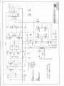
ohm operation as shipped. The 150 ohm input is obtained by strapping the socket terminals as shown on the schematic.
Both inputs may be used simultaneously provided the input to 1 and 2 is built out with a 100,000 ohm resistor in series with
the high side of the line to prevent excessive loading or shorting of the low impedance input.
OUTPUT CONNECTIONS
Output taps for nominal loads of 8, 16, and 32 ohms (70 volt line) are provided. Connections and strapping are shown
below.
Speaker Matching: Use the output tap which most nearly equals the total speaker impedance. If the load impedance
falls between two output tap values, use the lower tap.
70 Volt Line: The constant voltage distribution system (70 volt line) permits connection of a large number of speakers,
each to operate at the power level desired, without regard for the impedance involved. In this system, each speaker is
equipped with a transformer which has a number of taps rated in terms of power and the tap is selected which gives the
desired speaker power. The total power required for the speakers should be equal to or less than the amplifier power rating.
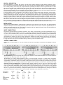
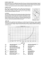
Protection of Horn Loaded Drivers: In industrial paging systems, stadium, arena or other voice reinforcing systems
which require excellent intelligibility over high noise levels, diaphragm type driver units coupled to horns are used. When
these are used without loudspeaker dividing networks (used in two-way speaker systems), the low frequency energy applied
to the driver voice coils must be limited. This protection is provided in the 1570B Amplifier by means of an R-C high pass
filter in V-1 grid circuit (see schematic). As shipped, capacitors C9 and C10 are strapped out. By cutting one or both of
these straps attenuation is introduced as shown in the table, depending on the impedance of the source.
CPS
Source Impedance Cut Strap 250 500 1000 2000
100,000 Ohm B -4.0 db -1.5 db -.5 db -.2 db
A -3.0 -1.0 -.3 -.2
A and B -7.0 -2.5 -.8 -.3
Lo
w
B -5.2 -2.0 -.7 -.2
(Approximately A -8.5 -4.0 -1.5 -.5
correct to
15,000 ohms)
A and B -12.5 -6.2 -2.5 -.7

POWER CONNECTIONS
The power transformer of the 1570B Amplifier has primary taps for 117 and 128 volts and is shipped with the 128 volt
tap (white lead) connected. Use of the 128 volt tap for all line conditions will extend component and tube life, reducing
maintenance to a minimum. Do not connect the 117 volt tap unless 24-hour line checks show that the line does not exceed
117 volts. For your convenience, these two leads are equipped with ring type terminals, the one in use being connected to
one terminal of the interlock microswitch and the unused terminal insulated with plastic tubing.
POWER OUTPUT
When making power output measurements, connect a jumper across the terminals of the
thermal breaker. Continuous sine wave output in the full power range may operate the
breaker, giving false readings, if the jumper is not used. In motor drive or other applica-
tions which require continuous sine wave full power output of the 1570B, the thermal
breaker should likewise be bridged out of the circuit.
CONTROLS
Two controls are provided: Volume control and AC power switch. Provision has been
made for mounting an accessory relay to provide plate power keying by remote control.
The mounting holes are located near the center of the chassis and are suitable for a Potter-
Brumfield type PR-3 relay or equivalent which should be mounted under the chassis.
Select a relay having the desired coil voltage. If control wiring and microphone lines are
carried in the same conduit, use a DC type relay. The white wire from the cable form to
terminal 6 on V-9 tube socket should be transferred from this terminal to one contact on
the relay. Connect the other relay contact to terminal 6, V-9 socket.
SERVICING
When the top cover is removed for tube replacement, etc., an interlock switch interrupts the AC line voltage to the power
transformer. Do not attempt service work on this amplifier with AC line voltage on, as approximately 1,000 volt potentials
occur at various points. Discharge all filter condensers before making continuity or resistance measurements. Routine ser-
vicing may then be done using the schematic for pertinent data reference. If high voltage measurements must be made,
proceed with caution.
PARTS LIST
C1
.0002 mfd. ±10%, 600v ceramic, Erie GP2-331
R18
75,000 ohms, 20 watt, Ohmite Brown Devil
C2, 3
.22 mfd., 400v, Astron BP4-22
R19
5 ohms, 50 watt, Ohmite 0400A
C4, 5
.1 mfd., 600v, CD PM6 P 1
R20
10 ohms ±10%, 1/2 watt
C6
40x40 mfd., 500v, Mallory FP288
P1
Altec Lansing 12435
C7, 11
120 mfd., 200v, Mallory FP121
BR1
Klixon CA3 Thermal Breaker
C8
6 mfd., 1000v, Tobe-Deutchmann TAB-1006
PL1
G.E. Mazda #44
C9
,0056 mfd. ±10%, 600 v ceramic, Erie 811
T1
Peerless 16492
C10
.0022 mfd. ±10%, 600v ceramic, Erie GP-2
T2
Peerless 6410
R1
1000 ohms ±10%, 1/2 watt
L1
Peerless 17173
R2
330,000 ohms ± 5%, 1 watt
L2
Peerless 17266
R3, 21
100,000 ohms ±10%, 1/2 watt
S1
Altec Lansing 12763
R4, 5, 9, 10, 17 100,000 ohms ±10%, 1 watt
S2
Interlock, V3-1 Microswitch
R6, 7
2.2 megohms ±10%, 1/2 watt
RS1, 2
G.E. 1N1695 Silicon Rectifier
R8
1800 ohms ±10%, 1/2 watt
V1
12AX7 Vacuum Tube
R11, 12
330,000 ohms ± 10%, 1/2 watt
V2
6SN7GTB Vacuum Tube
R13
82,000 ohms ±10%, 1/2 watt
V3, 4
6W6GT Vacuum Tube
R14
600 ohms, 5 watt, Ward Leonard Type 5
V5, 6
811-A Vacuum Tube
R15, 16
100 ohms ±10%, 1/2 watt
V7, 8, 9, 10
5R4GY Vacuum Tube

-
 1
1
-
 2
2
-
 3
3
-
 4
4


Altec Lansing 1570B Operating instructions
- Type
- Operating instructions
Ask a question and I''ll find the answer in the document
Finding information in a document is now easier with AI
Related papers


Other documents
-
AUDAC WS500 Installation guide
-
 solarcentre ASTRON Quick start guide
-
Bauer 707 Instruction book
-
 Langevin 128X-A Installation and Service Manual
-
 Hallicrafters SX-100 MARK IA Operating And Service Instructions
-
 DYNACO Mark VI User manual
-
Hafler DH-500 Amplifier User manual
-
 Hallicrafters HT-40 MK1 Operating And Service Instructions
-
 National Products NC-300 User manual
-


