
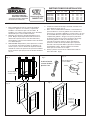
INSTALLATION INSTRUCTIONS
MODEL: 52WH344P, 52WH344PF,
52WH344DP, 52WH346DP,
52WH344DPF, 52WH346DPF
RECESSED MOUNTED, STEEL
MEDICINE CABINETS
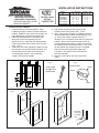
INSTALLATION of CABINET
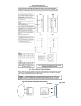
1. Carefully remove all packing material. Place
hardware packages, shelves and door aside until
needed. Hardware and shelves are located in the
fillers identified by “Hardware enclosed” tape.
2. Determine desired location of cabinet on wall.
Mark wall to show wall opening size (see
dimension chart). Generally, the recommended
height to the center of the cabinet is 64” from the
floor. (Fig. 1)
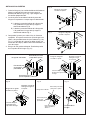
3. CAUTION: Wall studs, plumbing or electrical lines
that interfere must be removed or relocated. Cut
wall opening, being careful not to damage the
surrounding wall surface. Insert framing to
support all plaster board edges.
4. Prepare the mounting screws by placing the
screws into the clear plastic bases. (Fig. 2)
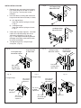
5. Note: For ease of installation, an additional person is
recommended.Insert cabinet into wall opening. (Fig.
3) Ensure the cabinet is plumb and level. If
necessary use a carpenter’s level and shim corners of
cabinet. Secure to wall studs through the four (4)
mounting holes inside cabinet, using the screws that
have been placed into the plastic bases. (Fig. 4) Do
not over tighten the mounting screws as the body
side wall may bend and prevent proper shelf
installation. Only tighten screws until they are
flush with the body.
6. Snap the screw covers over the screw bases.
(Fig.5)
For help, call us
toll free!
1-800-637-1453
MODEL WALL OPENING OVERALL SIZE
NO. W H D W H D
52WH344P 14
1
/
4
34 4 15 35 5
52WH344PF 14
1
/
4
34 4 15 35 5
52WH344DP 14
1
/
4
34 4 15 35 5
52WH346DP 14
1
/
4
34 6 15 35 7
52WH344DPF 14
1
/
4
34 4 15 35 5
52WH346DPF 14
1
/
4
34 6 15 35 7
Fig. 3
Wall
Opening
Cabinet
Body
Fig. 2
Fig. 5
Snap on Cover
Cover
Base
Screw
Fig. 1
Insert screw
through clear
plastic base
Fig. 4
Mounting
Screws
Mounting
screw into
mounting
hole

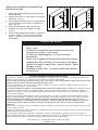
INSTALLATION of DOORS
1. Remove hinges and screws from hardware
bag. Mount hinge unit on door as shown in
Fig. 6 and Fig. 7 securing with screws
provided.
2. Install the door by inserting door side of the
hinge into the bracket on the body as shown;
A) 125 degree hinge
Insert door side of clip hinge as shown
in Fig. 8
B) 170 degree hinge
Insert door side of clip hinge as shown
in Fig. 9
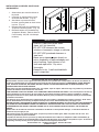
3. Check door for proper alignment. If the door
needs to be adjusted please refer to the
adjustment procedures in Fig. 10 and
Fig. 11. Door edges should be aligned with
the edges of the body and should fit evenly
to the face of the body.
4. 125 degree hinge only: Snap on hinge
cover plate. (Fig. 12)
Fig. 11Fig. 10
125 Degree Hinge
This screw for
up and down
adjustment
This screw
for depth
adjustment
This screw
for left and right
adjustment
170 Degree Hinge
This screw for
up and down
adjustments
This screw
for depth
adjustments
This screw
for left and right
adjustments
Fig. 6
Fig. 7
170 Degree Hinge
Mounted to Door
Fig. 8
Fig. 9
Hook bottom of
hinge into place
on the bracket
Press down
on hinge until it
clips in place
170 Degree Hinge
Mounted to Cabinet
125 Degree Hinge
mounted to Cabinet
Hook bottom of
hinge into place
on the bracket
Press down
on hinge until
it clips in place
125 Degree Hinge
Mounted to Door
2
Fig. 12
Hinge Cover

Fig. 14Fig. 13
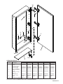
INSTALLATION of SHELVES, HOLE PLUGS
AND BUMPERS
1. Select where you want the shelves to
be placed.
2. Insert two (2) shelf brackets at each
end of the shelf location. (Fig. 13)
3. Set shelves in place on the shelf
brackets, pressing down on shelf to lock
in place. (Fig. 13)
4. Remove hole plugs from hardware bag
and place in remaining holes. ( Fig. 14)
5. Remove bumpers from hardware bag
and position to body. (Refer to Service
Parts Drawing - Key No. 9 for bumper
locations).
BROAN-NUTONE ONE YEAR LIMITED WARRANTY
Broan-NuTone warrants to the original consumer purchaser of its product that such products will be free from defects in
materials or workmanship for a period of one year from the date of original purchase. THERE ARE NO OTHER WARRAN-
TIES, EXPRESS OR IMPLIED, INCLUDING, BUT NOT LIMITED TO, IMPLIED WARRANTIES OF MERCHANTABILITY OR
FITNESS FOR A PARTICULAR PURPOSE.
During this one-year period, Broan-NuTone will, at its option, repair or replace, without charge, any product or part which is
found to be defective under normal use and service.
THIS WARRANTY DOES NOT EXTEND TO FLUORESCENT LAMP STARTERS AND TUBES. This warranty does not cover (a)
normal maintenance and service or (b) any product or parts which have been subject to misuse, negligence, accident,
improper maintenance or repair (other than by Broan-NuTone), faulty installation or installation contrary to recommended
installation instructions.
The duration of any implied warranty is limited to the one-year period as specified for the express warranty. Some states
do not allow limitation on how long an implied warranty lasts, so the above limitation may not apply to you.
BROAN-NUTONE’S OBLIGATION TO REPAIR OR REPLACE, AT BROAN-NUTONE’S OPTION, SHALL BE THE PURCHASER’S
SOLE AND EXCLUSIVE REMEDY UNDER THIS WARRANTY. BROAN-NUTONE SHALL NOT BE LIABLE FOR INCIDENTAL,
CONSEQUENTIAL OR SPECIAL DAMAGES ARISING OUT OF OR IN CONNECTION WITH PRODUCT USE OR PERFOR-
MANCE.
Some states do not allow the exclusion or limitation of incidental or consequential damages, so the above limitation or
exclusion may not apply to you.
This warranty gives you specific legal rights, and you may also have other rights, which vary from state to state. This
warranty supersedes all prior warranties.
To qualify for warranty service, you must (a) notify Broan-NuTone at the address or telephone number stated below, (b)
give the model number and part identification and (c) describe the nature of any defect in the product or part. At all time of
requesting warranty service, you must present evidence of the original purchase date.
Broan-NuTone LLC, 926 West State Street, Hartford, WI 53027
(1-800-637-1453)
• Use only clean warm water and a
clean, soft, lint-free cloth.
• DO NOT USE cleaners that contain
solutions of ammonia, vinegar, or chlorine.
• DO NOT USE powdered cleansers or
steel wool.
• Never spray cleaning agent directly on
mirror, especially on exposed edges and
mirror backing. Apply cleaner to soft
cloth and wipe mirror. Dry mirror
thoroughly.
• Keep mirror dry. A well ventilated bath
room is important.
MIRROR CARE
3

1
2
3
4
5
5
6
3
2
7
8
9
10
4
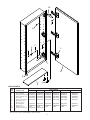
SERVICE PARTS
KEY PART NUMBER
NO. DESCRIPTION 52WH344P 52WH344PF 52WH344DP 52WH346DP 52WH344DPF 52WH346DPF
1 Door Assembly A97016167 A97016169 A97016173 A97016173 A97016174 A97016174
2 Hinge Assm w/screws A97016213 A97016213 A97016214 A97016214 A97016214 A97016214
3 Screw, hinge (4 req.) A99160423 A99160423 A99160423 A99160423 A99160423 A99160423
4 Hole Plug A99111239 A99111239 A99111239 A99111239 A99111239 A99111239
5 Screw cover & base A99111240 A99111240 A99111240 A99111240 A99111240 A99111240
6 Mounting Screw
#8x1
1
/
2
* (4 req.) ***** *
7 Shelf Supports A99111223 A99111223 A99111223 A99111223 A99111223 A99111223
8 Shelf, glass A99050275 A99050275 A99050275 A99050276 A99050275 A99050276
9 Bumpers (2 req.) 7189 7189 7189 7189 7189 7189
10 Hinge Cover (2 req.) A99111249 A99111249 -- -- -- --
*Standard hardware - may be purchased locally.
Order replacement parts by “PART NUMBER” - NOT by “KEY NO.”
Page is loading ...
Page is loading ...
Page is loading ...
Page is loading ...
-
 1
1
-
 2
2
-
 3
3
-
 4
4
-
 5
5
-
 6
6
-
 7
7
-
 8
8


Ask a question and I''ll find the answer in the document
Finding information in a document is now easier with AI
in other languages
Related papers
-
Jensen 52WH246DPF User manual
-
-
-
Jensen 52WH344DPX Installation guide
-
-
-
-
NuTone 614X Operating instructions
-
Jensen 1451X Operating instructions
-
Other documents
-
Broan 56SS184CSN Installation guide
-
-
-
-
none 9000CX Installation guide
-
-
-
-
-
 Deco Mirror 8208 Installation guide
