Page is loading ...

MADE IN ITALY
• Torri Faro
• Lighting Towers
• Tours D’éclairage
• Torres de iluminación
• Lichtmasten
• Torres de iluminação
• По вышкам
• Verlichting Towers
8B9729003
LIGHT & ENERGY
TF II9 Y (STAGE V)
Codice
Code
Code
Codigo
Kodezahl
Código
Код
Code
Edizione
Edition
Édition
Edición
Ausgabe
Edição
Издание
Editie
04.2019
USE AND MAINTENANCE MANUAL
TRANSLATION OF THE ORIGINAL INSTRUCTIONS – ENGLISH
language


07/10/13 8B972_EN
ENGLISH
ENGLISH
REV.0-10/16
INDEx
0. GENERAL INFORMATION
M1.1
INTRODUCTION
.................................................................................................................PAG. 4
M1.4
CE MARK
...........................................................................................................................PAG. 5
M2
SYMBOLS AND SAFETY PRECAUTIONS
..............................................................................PAG. 6
M2.1
WARNINGS
........................................................................................................................ PAG. 7
M2.5...
SAFETY RULES
.................................................................................................................. PAG. 8
1. GENERAL INFORMATION OF THE MACHINE
M0
DESCRIPTION OF THE MACHINE
........................................................................................PAG. 10
RECORDING DATA
..............................................................................................................PAG. 11
2. TRANSPORT AND HANDLING
M3
MACHINE UNPACKING
.......................................................................................................PAG. 12
M4.2...
TRANSPORT AND HANDLING
.............................................................................................PAG. 13
3. INSTALLATION AND USE
M2.7
INSTALLATION
................................................................................................................... PAG. 15
M20...
SET-UP FOR OPERATION DIESEL ENGINE
...........................................................................PAG. 16
EARTHING
.........................................................................................................................PAG. 18
M21
STARTING AND STOPPING EP6
..........................................................................................PAG. 19
M23.1...
START-UP
..........................................................................................................................PAG. 20
M31
CONTROLS
........................................................................................................................PAG. 22
M39.12..
ENGINE PROTECTION EP6
..................................................................................................PAG. 23
4. MAINTENANCE
M40.3...
TROUBLE SHOOTING
.........................................................................................................PAG. 28
M43
MAINTENANCE
..................................................................................................................PAG. 30
M43.3
LIGHTING TOWER MAINTENANCE
......................................................................................PAG. 31
5. TECHNICAL INFORMATIONS
M1.5...
TECHNICAL DATA
..............................................................................................................PAG. 32
M1.5.2
ILLUMINATION DIAGRAM ...................................................................................................
PAG. 34
M2.7.1...
DIMENSIONS
..................................................................................................................... PAG. 35
M60
ELECTRICAL SYSTEM LEGENDE
.........................................................................................PAG. 38
M61...
ELECTRICAL SYSTEM
........................................................................................................PAG. 39

10/10/02 M1-1_EN
ENGLISH
ENGLISH
REV.0-10/02
M
1.1
INTRODUCTION
Dear Customer,
We wish to thank you for having bought a high quality set.
Our sections for Technical Service and Spare Parts will work at
best to help you if it were necessary.
To this purpose we advise you, for all control and overhaul
operations, to turn to the nearest authorized Service Centre,
where you will obtain a prompt and specialized intervention.
+ In case you do not prot on these Services and some arts
are replaced, please ask and be sure that are used exclusi-
vely original parts; this to guarantee that the performances
and the initial safety prescribed by the norms in force are
re-established.
+The use of non original spare parts will cancel immediately
any guarantee and Technical Service obligation.
NOTES ABOUT THE MANUAL
Before actioning the machine please read this manual atten-
tively. Follow the instructions contained in it, in this way you will
avoid inconveniences due to negligence, mistakes or incorrect
maintenance. The manual is for qualied personnel, who knows
the rules: about safety and health, installation and use of sets
movable as well as xed.
You must remember that, in case you have difculties for use
or installation or others, our Technical Service is always at your
disposal for explanations or interventions.
The manual for Use Maintenance and Spare Parts is an inte-
grant part of the product. It must be kept with care during all
the life of the product.
In case the machine and/or the set should be yielded to another
user, this manual must also given to him.
Do not damage it, do not take parts away, do not tear pages and
keep it in places protected from dampness and heat.
You must take into account that some gures contained in it
want only to identify the described parts and therefore might
not correspond to the machine in your possession.
INFORMATION OF GENERAL TYPE
In the envelope given together with the machine and/or set you
will nd: the manual for Use Maintenance and Spare Parts,
the manual for use of the engine and the tools (if included in
the equipment), the guarantee (in the countries where it is
prescribed by law).
+ NOTICE: the manufacturer, who keeps the faculty, apart
the essential characteristics of the model here described
and illustrated, to bring betterments and modications to
parts and accessories, without putting this manual uptodate
immediately.
The Manufacturer shall not be liable for ANY USE OF THE PRO-
DUCT OTHER THAN THAT PRECISELY SPECIFIED IN THIS
MANUAL and is thus not liable for any risks which may occur as
a result of IMPROPER USE. The Company does not assume
any liability for any damage to persons, animals or property.
Our products are made in conformity with the safety norms in
force, for which it is advisable to use all these devices or informa-
tion so that the use does not bring damage to persons or things.
While working it is advisable to keep to the personal safety
norms in force in the countries to which the product is destined
(clothing, work tools, etc.).
Do not modify for any motive parts of the machine (fastenings,
holes, electric or mechanical devices, others..) if not duly au-
thorized in writing: the responsibility coming from any potential
intervention will fall on the executioner as in fact he becomes
maker of the machine.

10/10/02 M1-4_EN
ENGLISH
ENGLISH
TEMP.
°CRPM
n
IP
kW
ALTIT.
Kg
m
G
P. F.
Hz
V(V)
I(A)
KVA
TYPE
I.CL.
SERIAL N°
Made in UE-ITALY
TYPE/N°
VOLTAGE(V)
POWER(W)
LTPPOWER IN ACCORDANCEWITH ISO 8528
Pmax
1
4
5
6
7
8
9
10
11
14
17
12
15
18
13
16
19
20
21
22
23
24
25
26
2
3
Any of our product is labelled with CE marking attesting its conformity to appliable directives and also the fulllment of safety
requirements of the product itself; the list of these directives is part of the declaration of conformity included in any machine
standard equipment.
Here below the adopted symbol:
CE marking is clearly readable and unerasable and it can be either part of the data-plate.
REV.7-02/14
M
1.4.1
CE MARKING
LIGHTING TOWERS
Furthermore, on each model it is shown the noise level value; the symbol used is the following:
The indication is shown in a clear, readable and indeleble way on a sticker.
1. Name or brand supplier
2. Light tower model
3. Serial number | registration number
4. Year of production
5. Type and number of lamps
6. Lamps voltage supply
7. Lamps total power
8. Generating set rated frequency
9. Generating set power factor cosφ
10. Generating set insulation class
11. Generating set rated power (kVA/kW)
12. Generating set rated power (kVA/kW)
13. Generating set rated power (kVA/kW)
14. Generating set rated voltage (V)
15. Generating set rated voltage (V)
16. Generating set rated voltage (V)
17. Generating set rated current(A)
18. Generating set rated current(A)
19. Generating set rated current(A)
20. Engine rated speed
21. Engine maximum power
22. Generating set max ambient temperature
23. Generating set rated altitude (above sea level)
24. IP degree protection
25. Dry weight (kg)
26. Any additional information

13/11/14 M2_EN
ENGLISH
ENGLISH
REV.2-06/10
M
2
SYMBOLS AND SAFETY PRECAUTIONS
SYMBOLS IN THIS MANUAL
- The symbols used in this manual are designed to call your
attention to important aspects of the operation of the machine
as well as potential hazards and dangers for persons and
things.
Moreover, this symbolism intends to draw your attention
with the aim to give you indications for a correct use and,
as a result, to obtain a good operation of the machine or
equipment used.
SAFETY PRECAUTIONS
WARNING
This heading warns of situations which could result in injury
for persons or damage to things.
DANGEROUS
This heading warns of an immediate danger for persons as
well for things. Not following the advice can result in serious
injury or death.
CAUTION
To this advice can appear a danger for persons as well as
for things, for which can appear situations bringing material
damage to things.
IMPORTANT
NOTE
ATTENTION
These headings refer to information which will assis you in
the correct use of the machine and/or accessories.
!
!
!
!
!
!
SIMBOLS
STOP - Read absolutely and be duly attentive
Read and pay due attention
DANGER
!
GENERAL ADVICE - If the advice is not respec-
ted damage can happen to persons or things.
HIGH VOLTAGE - Attention High Voltage.There
can be parts in voltage, dangerous to touch. The
non observance of the advice implies life danger.
FIRE - Danger of ame or re. If the advice is not
respected res can happen.
HEAT - Hot surfaces. If the advice is not respected
burns or damage to things can be caused.
EXPLOSION - Explosive material or danger of
explosion. in general. If the advice is not respected
there can be explosions.
ACIDS - Danger of corrosion. If the advice is not
respected the acids can cause corrosions with
damage to persons or things.
PRESSION - Danger of burns caused by the
expulsion of hot liquids under pressure.
PROHIBITIONS
It is prohibited to smoke while lling the tank with fuel.
The cigarette can cause re or explosion. If the
advice is not respected res or explosions can
be caused.
It is prohibited to use water to quench res on the electric
machine
If the advice is not respected res or damage to
persons can be caused.
Use only with non inserted voltage -
It is prohibited to make interventions before having
disinserted the voltage.
ACCES FORBIDDEN to non authorized peaple.
ADVICE
Use only with safety clothing -
It is compulsory to use the personal
protection means given in equipment.
WRENCH - Use of the tools. If the advice is not
respected damage can be caused to things and
even to persons.

13/11/14 M2_EN
ENGLISH
ENGLISH
+ FIRST AID. In case the operator shold be sprayed by accident, from corrosive liquids a/o hot toxic gas or whate-
ver event which may cause serious injuries or death, predispose the rst aid in accordance with the ruling labour
accident standards or of local instructions.
+ FIRE PREVENTION. In case the working zone,for whatsoever cause goes on re with ames liable to cause severe
wounds or death, follow the rst aid as described by the ruling norms or local ones.
Skin contact Wash with water and soap
Eyes contact Irrigate with plenty of water, if the irritation persists contact a specialist
Ingestion Do not induce vomit as to avoid the intake of vomit into the lungs, send for a doctor
Suction of liquids from
lungs
If you suppose that vomit has entered the lungs (as in case of spontaneous vomit) take the subject to the hospital with the
utmost urgency
Inhalation In case of exposure to high concentration of vapours take immediately to a non polluted zone the person involved
EXTINCTION MEANS
Appropriated Carbonate anhydride (or carbon dioxyde) powder, foam, nebulized water
Not to be used Avoid the use of water jets
Other indications Cover eventual shedding not on re with foam or sand, use water jets to cool off the surfaces close to the re
Particular protection Wear an autorespiratory mask when heavy smoke is present
Useful warnings Avoid, by appropriate means to have oil sprays over metallic hot surfaces or over electric contacts (switches,plugs,etc.).
In case of oil sprinkling from pressure circuits, keep in mind that the inamability point is very low.
REV.2-06/10
M
2.1
WARNINGS

13/11/14 M2.5 (GE-TF)_EN
ENGLISH
ENGLISH
GENERAL SAFETY INSTRUCTIONS
+ NOTE: the information contained in this manual are
subject to change without notice.
The instructions in this manual are intended as indicative only.
It is the responsibility of the owner/operator to evaluate risks
and potential damages in relation to the use of the product in
the specic conditions of application. Remember that the non
observance of the indications of this manual may result in da-
mage to people or things.
In all cases, however, it is understood that the use shall be in
compliance with the applicable laws/regulations.
• Before operating the machine, read carefully the safety in-
structions contained in this manual and other manuals sup-
plied (engine, alternator, etc.).
• All operations, handling, installation, use, maintenance, re-
pair should be carried out by authorized and qualied per-
sonnel.
• When operating, wear personal protective equipment (PPE):
footwear, gloves, helmet, etc..
• The owner is responsible for maintaining the equipment in
safe conditions.
Use only in perfect technical conditions
The machinery or equipment must be used in perfect tech-
nical condition. Remove immediately any defects that may
affect the safe conditions of use.
• Before starting to use this equipment it is important to take
knowledge of all the controls of the machine, all its functions
and its correct installation in order to avoid accidents to pe-
ople and damage to the machine itself. In particular, it is
important to know how to stop the equipment quickly in case
of emergency.
• Do not allow the use of the machine to people unless pre-
viously instructed with all the information for a proper, safe
use.
• Forbid the access in the operational area to non authorized
personnel, children and pets so as to protect them from pos-
sible injury caused by any part of the machine.
SAFETY PRECAUTIONS DURING HANDLING AND TRAN-
SPORTATION
• Lift the machine using only the points allocated for this fun-
ction.
The lifting eye (or eyes) and the correct positioning of the
forks of the forklift are marked with specic adhesives.
• Clear the operational area of possible obstacles and all un-
necessary personnel.
• Always use lifting equipment properly sized and controlled
by enabled bodies.
• It is forbidden to set on the frame of the equipment objects
or accessories that alter weight and center of gravity and
cause stresses not foreseen to the lifting points.
• Do not submit the machine and the lifting equipment to
swinging or shock which may transmit dynamic stress to the
structure.
Equipments with trailers or site tows
• Never drag the machine without trailer (or site tow)
• Check for a correct assembly of the machine to the towing
device.
• Always make sure that the hook of the vehicle is suitable for
towing of the total mass of the trailer.
• Do not tow the trailer if the coupling devices are worn or
damaged.
• Check for proper tire pressure.
• Do not replace the tires with types different from the original
ones.
• Check that the brakes and the optical signaling of the trailer
are working properly.
• Verify that the bolts of the wheels are in place and well
tightened.
• Do not park the machine (on trailer or site tow) on a steep
slope.
For the stops, not followed by a work session, always enga-
ge the parking brake and / or block the wheels by means of
wheel chocks.
• Do not tow the trailer on bumpy roads.
• Do not exceed the maximum permissible speed on public
roads of 80 km/h with the trailer, in any case comply with the
legislation applicable in the country of use.
• Do not use the site tow on public roads, this is intended for
use only in private and delimited areas. The maximum per-
mitted speed is 40 km/h on smooth surfaces (asphalt or con-
crete), adapt in each case the speed to the type of ground.
SAFETY PRECAUTIONS DURING INSTALLATION AND
USE
• Always locate the machine on a at and solid ground, so as
to avoid tipping, slipping or falling during operation. Avoid
using the machine on slopes greater than 10 degrees.
• Make sure the area immediately surrounding the machine is
clean and free from debris.
• Connect the machine to an earthing system according to
the regulations in force at the place of installation. Use the
ground terminal on the front of the machine.
• Do not use the machine with wet or damp hands and / or
clothing.
• Use plugs suitable for the output sockets of the machine and
make sure that electrical cords are in good condition.
• The machine must always be positioned so that the exhaust
gases are dispersed in the air without being inhaled by peo-
ple or living beings.
• If you use the machine indoors is necessary that the instal-
lation is designed and built by skilled technicians in a wor-
kmanlike manner.
• During normal operation, keep doors closed. The access to
the internal parts should be allowed only for maintenance
reasons.
• Do not place objects or obstructions in the vicinity of the air
intakes and air outlets, a possible overheating of the gene-
rator could cause a re.
• Keep area near to the mufer free from objects such as
rags, paper, cardboard. The high temperature of the mufer
could cause the burning of objects and cause re.
• Immediately stop the machine in case of malfunction.
Do not restart the machine without rst having found and
xed the problem.
REV.0-03/15
M
2.5
SAFETY RULES
GENERATING SETS - LIGHTING TOWERS

13/11/14 M2.5 (GE-TF)_EN
ENGLISH
ENGLISH
SAFETY PRECAUTIONS DURING MAINTENANCE
• Make use of qualied personnel to carry out maintenance
and troubleshooting.
• It is mandatory to stop the engine before performing any
maintenance on the machine.
• Always use protective devices and suitable equipment.
• Do not touch the engine, the exhaust pipes and the mufer
during operation or immediately after. Allow the engine to
cool before performing any operation.
• With the machine running pay attention to moving parts
such as fans, belts, pulleys.
• Do not remove the protections and the safety devices unless
absolutely necessary, restore them after completion of the
maintenance or repair.
• Do not refuel while the engine is running or hot. Do not smo-
ke or use naked ames when refueling.
• Refuel only outdoors or in well ventilated areas.
• Avoid spilling fuel, especially on the engine. Clean and dry
any leaks before restarting the machine.
• Slowly unscrew the cap of the fuel tank and put it back
always after refueling.
• Do not ll the tank completely to allow for expansion of the
fuel inside.
• Do not remove the radiator cap when the engine is running
or still hot, the coolant may spurt out and cause serious
burns.
• Do not handle the battery without the use of protective glo-
ves, the battery uid contains sulfuric acid, which is very cor-
rosive and dangerous.
• Do not smoke, avoid any naked ames or sparks near the
battery, the vapors exhaled could cause the battery to explo-
de
REV.0-03/15
M
2.5.1
SAFETY RULES
GENERATING SETS - LIGHTING TOWERS
SAFETY PRECAUTIONS DURING HANDLING AND TRAN-
SPORTATION
• Before moving a lighting tower lower the telescopic mast
and block properly all movable parts such as the access do-
ors, the mast, the outriggers, the oodlights.
• Check the fastening of the wheels of the trolley.
SAFETY PRECAUTIONS DURING INSTALLATION AND
USE
• Make sure the area above the lighting tower is free from
overhead cables or other obstacles.
• Before raising the mast extract the outriggers located at
the sides of the machine. Acting on the outriggers level the
lighting tower making use of the bubble, so as to bring the
equipment in a horizontal position. Make sure that the to-
wer rests securely on the outriggers. If the lighting tower is
mounted on road trailer pull the handbrake.
• Do not operate the lighting tower if the wind speed exceeds
the safe speed indicated or if it is expected the arrival of
storms or thunderstorms in the area.
• Lower the telescopic mast when the tower is not used.
• Always check the good condition of the power cable before
connecting the lighting tower to the generating set.
• Do not touch and do not place objects on the lamps during
operation or immediately after use. The lamps become very
hot.
• Do not turn on the lamps without the protective glass or with
the same broken or damaged.
• Make sure all the ropes and the manual winch are in perfect
condition.
• Place the lighting tower in order to avoid that the winch can
receive shocks which may cause damage to the automatic
brake.
SAFETY PRECAUTIONS DURING MAINTENANCE
• Turn off the generating set or unplug the power cable before
carrying out any type of maintenance on the lighting tower.
• Always cut off power to the lamps and wait for their cooling
before performing any maintenance or replacement.
• Before carrying out any type of maintenance or repairs on
the generating set refer to the manual of the generating set
and the other manuals supplied.
ATTENTION
The lighting towers is designed to be used with a generating
set or with a xed mass on its base. The weight and positio-
ning of the generating set on the base are essential for the
safety of the lighting tower.
Failure to comply with this provision causes a serious danger
of tipping or instability during operation and during handling
with site tow If necessary, contact the service.
!
ADDITIONAL PRECAUTIONS FOR LIGHTING TOWERS

07/10/13 8B972_EN
ENGLISH
ENGLISH
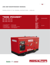
The Lighting Tower a compact and functional model which integrates the functions of lighting tower and electric power
generator into a single machine.
The lighting tower is composed of:
• A hydraulic telescopic mast, which can be raised up to a maximum height of 9 meters and manually oriented within a range of
340°
• A light assembly consisting of IP65 or higher oodlights and various types of lamps: LED, metal halide, exc..
• A silent generator driven by a water-cooled, low fuel consumption engine
• A command and control panel for the overall management and protection of the lighting tower
• 4 outriggers, 2 extendable and adjustable in height, to ensure the stability of the tower on any working surface
• The lighting tower is on base but can be equipped with a road trailer or a site tow.
M
0
DESCRIPTION OF THE MACHINE
REV.2-04/19
FLOODLIGHTS
ASSEMBLY
SOUNDPROOF
GENERATOR SET
HYDRAULIC
TELESCOPIC MAST
ROAD TRAILER
OR SITE TOW
COMMAND AND
CONTROL PANEL

0.1
RECORDING DATA
REV.1-11/14
The manual is for the range of machines indicated on the front cover.
With the scope to facilitate the search of the spare parts and maintain information of the bought machine, is necessary to record
some data.
Please write the requested data inside the squares to side:
1. Model of machine
2. Serial number of the machine
3. Serial number of the engine
4. Name of the dealer where bought the machine
5. Address of the dealer
6. Phone number of the dealer
7. Date of the bought machine
8. Notes
RECORDING DATA
1.
2.
3.
4.
5.
6.
7.
8.
16/10/15 Registrazione Dati_EN
ENGLISH
ENGLISH

30/03/00 M3_EN
ENGLISH
ENGLISH
NOTE
!
+ Be sure that the lifting devices are: correctly mounted,
adequate for the weight of the machine with it’s packaging,
and conforms to local rules and regulations.
When receiving the goods make sure that the product has
not suffered damage during the transport, that there has
not been rough handling or taking away of parts contained
inside the packing or in the set.
In case you nd damages, rough handling or absence of
parts (envelopes, manuals, etc.), we advise you to inform
immediately our Technical Service.
For eliminating the packing materials, the User must
keep to the norms in force in his country.
1) Take the machine (C) out of the shipment packing. Take out
of the envelope (A) the user’s manual (B).
2) Read: the user’s manual (B), the plates xed on the machine,
the data plate.
2
B
A
1
C
REV.1-02/04
M
3
MACHINE UNPACKING

14/10/13 M4-2 (TF Integrata 9m)_EN
ENGLISH
ENGLISH
GENERAL PRECAUTION WHEN HANDLING THE MACHI-
NE.
In order to minimize the dangers involved in moving the equip-
ment it is important to follow carefully the requirements below:
• The transport must always be done with the engine off, with
electrical cables and starting battery disconnected, fuel
tank empty.
• Clear the moving zone of all possible obstacles and from all
unnecessary personnel.
• Use properly sized lifting equipment regularly submitted to
major overhaul by an authorized organisation. It is prohi-
bited to fasten objects or accessories on the lighting
tower baseframe that may modify weight and center of
gravity and may cause movements unforeseen by the lifting
eyes.
• Do not subject the lighting tower and lifting equipment to
abrupt or undulating movements that pass on stress dyna-
mics to the structure.
• Do not lift the equipment at heights greater than those
strictly necessary.
• To access the attachment points on the roof of the machine,
use approved ladders only. Climb the ladder being suppor-
ted by a second operator and wear special non-slip shoes.
MOVING THE GENERATING SET VIA FORKLIFT
When lifting with a forklift it is necessary to:
• Insert the forks of the forklift into the specic pockets located
sideways and frontally on the baseframe, as indicated in the
gures.
• Fully insert the forks so that they stick out from the opposite
side and be careful to keep the equipment in horizontal po-
sition.
Stickers on the base indicate where to place the lifter forks.
ATTENTION
During handling of the lighting tower is essential to pay
close attention.
All handling operations must be performed by qualied
personnel.
For the characteristics of weight and size, an error du-
ring the handling of the machine may result in serious
damage to the surrounding people and to the machine
itself.
!
MOVING THE GENERATING SET VIA CABLES OR CHAINS
When lifting the genset with the aid of cables or chains it is ne-
cessary to use equipment periodically checked by a licensed
organisation. Hook the cables only on to the points provided
for this use and shown via the appropriate stickers.
OK
NO
NO
OK
OK
NO
NO
NOOK
OK
NO
REV.0-10/13
M
4.2
TRANSPORT AND HANDLING
LIGHTING TOWER WITH GENERATING SET 9M

14/10/13 M4-2 (TF Integrata 9m)_EN
ENGLISH
ENGLISH
MOVING BY SITE TROLLEY / TRAILER
BEFORE STARTING TO TOW DO THE FOLLOWING:
• Fully raise the outriggers and lock the crank with its clamp
• Fully retract the outriggers up to snap the locking pins
• Use the crank of the jockey wheel to raise / lower the draw-
bar on the hook of the towing vehicle lock the hook
• lock the hook
• Connect the cable from the trailer to the towing vehicle and
make sure all the lights work properly
• Make sure that the doors are locked
• Check for proper tire ination of the trailer
CAUTION
the trailer can be driven only after you have done the
following:
• complete lowering of the mast
• engine shutdown
• positioning of the oodligths for the transportation.
!
ROAD TRAILER (CTV):
It is homologated for use on public roads. The maximum spe-
ed allowed is 80 km/h, in any case, the transportation laws in
force in the place of use shall be respected.
SITE TOW CTL:
this trailer is made by the manufacturer, it can not be towed on
public roads. Therefore it can only be used on private roads
and no through trafc zones.
The maximum speed allowed is 40 km/h on smooth surfaces
(asphalt, cement) and, in any case, the laws in force in the
place of use should be respected.
Always follow the directions below for any tipe of tow:
• Do not park the machine (on trailer or site tow) on a slant
ground.
• When parking always use the emergency/hand brake and/
or safety clamps.
• DO NOT tow the trailer on bumpy roads.
MACHINE TRANSPORTATION BY A MOTOR VEHICLE
During the transportation with a motor vehicle it is important to
use appropriate belts/straps to stabilise the unit, thus avoiding
that unexpected jumps or jolts can cause damage to the ba-
seframe and to the engine or even worse the loss or the over-
turning of the load. It is the carriers responsibility to always
respect the Highway Code in force.
REV.0-10/13
M
4.2.1
TRANSPORT AND HANDLING
LIGHTING TOWER WITH GENERATING SET 9M

07/10/13 8B972_EN
M
2.7
INSTALLAZIONE - INSTALLATION - INSTALLATION
INSTALACIÓN - LUFTZIRKULATION
INSTALAÇÃO - УСТАНОВКА - INSTALLATIE
REV.0-10/13

12/06/03 M20 (raff_acqua)_EN
ENGLISH
ENGLISH
LUBRICANT
RECOMMENDED OIL
The manufacturer recommends selecting AGIP engine oil.
Refer to the label on the motor for the recommended products.
Please refer to the motor operating manual for the recommended
viscosity.
REFUELLING AND CONTROL:
Carry out refuelling and controls with motor at level position.
1. Remove the oil-ll tap (24)
2. Pour oil and replace the tap
3. Check the oil level using the dipstick (23); the oil level must
be comprised between the minimum and maximum indica-
tors.
AIR FILTER
Check that the dry air lter is correctly installed and
that there are no leaks around the lter which could lead to
inltrations of non-ltered air to the inside of the motor.
BATTERY WITHOUT MAINTENANCE
The starter battery is supplied already
charged and ready for use.
Before starting the gen-set connect
the cable + (positive) to the pole + of
the battery, by properly tightening the
clamp. In case of models with warning
light: check the state of the battery by
means of the indicator placed in the upper part.
- Green colour: battery OK
- Black colour: battery to be recharged
- White colour: battery to be replaced
DO NOT OPEN THE BATTERY.
FUEL
Rell the tank with good quality diesel fuel, such as automobile
type diesel fuel, for example.
For further details on the type of diesel fuel to use, see the motor
operating manual supplied.
Do not ll the tank completely; leave a space of approx. 10
mm between the fuel level and the wall of the tank to allow for
expansion.
In rigid environmental temperature conditions, use special
winterized diesel fuels or specic additives in order to avoid
the formation of parafn.
ATTENTION
Stop engine when fueling. Do not smoke or use
open ames during refuelling operations, in order
to avoid explosions or re hazards.
Fuel fumes are highly toxic; carry out operations
outdoors only, or in a well-ventilated environment.
Avoid accidentally spilling fuel. Clean any even-
tual leaks before starting up motor.
!
ATTENTION
It is dangerous to ll the motor with too much oil, as its com-
bustion can provoke a sudden increase in rotation speed.
!
REV.2-04/15
M
20
SET-UP FOR OPERATION
(DIESEL ENGINE)
WATER COOLED SYSTEMS

12/06/03 M20 (raff_acqua)_EN
ENGLISH
ENGLISH
COOLING LIQUID
Remove the tap and pour the liquid coolant into the radiator;
the quantity and composition of the liquid coolant are indicated
in the motor operating manual. Replace the tap, ensuring it is
perfectly closed.
After relling operations, allow the motor to run for a brief time
and check the level, as it may have diminished due to air bub-
bles present in the cooling circuit; restore the level with water.
To replace the liquid coolant, follow the operations described
in the motor operating manual.
ATTENTION:
The engine cooling system is originally lled with coolant type:
AGIP ANTIFREEZE EXTRA
During the engine life it is strongly recommended to use the
same coolant type. This is because a coolant change would
require a careful cleaning of the cooling system, which is not
an easy job. A lack in tacking these precautions would result in
the mix of different additives used in different coolants which
would originate gelatinous substances capable of obstructing
the cooling system.
ATTENTION
Do not remove the radiator tap with the motor in operation or
still hot, as the liquid coolant may spurt out and cause serious
burns. Remove the tap very carefully.
ATTENTION
A qualied electrician should carry out electrical connec-
tions according to the norms in force.
!
ELECTRICAL CONNECTIONS
The electrical connection to the User system is a very impor-
tant operation: safety and good operation of the genset and
User system depend on a correct electrical connection.
Before supplying User system always check:
• that wires connecting gen-set to the user plant are suitable
to the supplied voltage and are in accordance to the appli-
cable rules;
• wire type, section and length have been calculated consi-
dering environment conditions and in force norms;
• ground is functioning correctly: earth fault relay device wor-
ks only if this connection is operating;
• that direction of the phases corresponds to the user plant
phase rotation, and none of the phases has been acciden-
tally connected to neutral.
REV.2-04/15
M
20.1
SET-UP FOR OPERATION
(DIESEL ENGINE)
WATER COOLED SYSTEMS

14/10/13 Messa a Terra_EN
ENGLISH
ENGLISH
REV.0-10/16
Earthing
EARTHING WITHOUT GROUND FAULT INTERRUPTER
The protection against electric shock from contact indirect is
ensured by the “electrical separation” with equipotential bonding
between all the exposed conductive parts of the generating set.
The generating set is NOT equipped with a earth leakage circuit
breaker because its windings are not connected to ground,
hence the machine should NOT be intentionally connected to
a grounding circuit.
The limitation of the extension of the electric circuit is very
important for safety, do not power supply to electric plants with
a length greater than 200 meters.
It is important that the power cords of the equipment are equip-
ped with the protective conductor, yellow-green cable, in order
to ensure the connection between the exposed conductive parts
of the generating set and the equipment; this provision does not
apply to the class II equipment (double insulation or reinforced
insulation) recognizable by the symbol
.
The cables must be suitable environment in which it operates.
It should be noted that with temperatures below 5°C PVC cables
become stiff and PVC insulation tends to cut to the rst fold.
The protection by electrical separation is NOT suitable if the
machine is destined to supply power complex plants or located
in special environments with greater risk of electric shock.
In these cases it is necessary to adopt security measures
electricity provided by law.
For EXAMPLE, you can install a GFI (Ground Fault Interrupter
or Earth Leakage Circuit Breaker) high sensitivity 30mA, and
grounding the Neutral of the generating set: this operation
must be performed by a qualied electrician or at a authorized
service provider.
The grounding of the generating set is now mandatory to ensure
protection against indirect contact by means of the GFI.
Connect the generating set to an earthing system via a cable
certain efciency using the ground terminal (12) on the machine.
EARTHING WITH GROUND FAULT INTERRUPTER
The grounding connection to an earthed installation is obliga-
tory for all models equipped with a differential switch (circuit
breaker). In these groups the generator star point is generally
connected to the machine’s earthing; by employing the TN or TT
distribution system, the differential switch guarantees protection
against indirect contacts.
In the case of powering complex installations requiring or em-
ploying additional electrical protection devices, the coordination
between the protection devices must be veried.
For the grounding connection, use the terminal (12); comply
to local and/or current regulations in force for electrical instal-
lations and safety
EARTHING WITH ISOMETER
Machines equipped with insulation resistance monitor allow
intentionally not to connect the ground terminal PE (12) to an
earthing system.
Located on the front of the machine the insulation resistance
monitor has the function of continuously monitoring the ground
insulation of live parts.
If the insulation resistance falls below the pre-set fault value,
the insulation resistance monitor will interrupt the supply of the
connected equipment.
It is important that the power cords of the devices are provided
with the green-yellow circuit protective conductor, so as to en-
sure the bonding among all the grounds of the equipment and
the ground of the machine; the latter provision does not apply
to equipment with double insulation or reinforced insulation.
NOTE: it is possible to connect the PE terminal (12) to an
own ground connection. In this case an IT earthing system is
accomplished, this means with the active parts isolated from
earth and the equipment cases grounded.
In this case, the insulation resistance monitor checks the insula-
tion resistance of the active parts both towards case and ground,
for example, the insulation towards ground of the power cables.

02/02/06 M21 (EP6)_EN.indd
ENGLISH
ENGLISH
NOTE
Do not alter the primary conditions of regulation and do not
touch the sealed parts.
NOTE
For safety reason the key must be kept by qualied personel.
CAUTION
RUNNING-IN
During the rst 50 hours of operation, do not use more than
60% of the maximum output power of the unit and check the
oil level frequently, in any case please stick to the rules given
in the engine use manual.
CAUTION
MACHINE WITH EMERGENCY BUTTON
Pressing the button the engine will stop immediately in any
working condition.
Turn clockwise to reset the button.
!
!
!
!
The starting of the unit can be effected in 3 different modes:
1) Start with EP6 key (Engine Control)
Put the “Local/Remote” selector on Local. Turn the key on
“ON”, the EP6 display shows, only on the machines with
mounted glow plugs for 5 secs, the symbol “UUUU”, then
the message “Sta” appears the engine can be started, for
then turn the key on “start” and start the engine.
On the display the word “Sta” remains for about 20 sec then
automatically disappears; the engine must be started within
20 secs, otherwise the EP6 blocks the starting and on the
display the word “fail” appears. Turning the key on “OFF” the
EP6 is reset and a new starting cycle can be xed.
Stop:
it is COMPULSORY to disconnect the load rst, then to stop
the engine turn the key on “OFF”.
2) Remote starting with TCM35
Put the “Local/Remote” selector on Local. Connect TCM35
to the plug on the front panel and put the switch on “0”.
Turn the key on ON in the EP6, wait for the various signals
to go out then press the button “AUTO” in the EP6 until the
led “AUTO” ashes.
Shift the switch on “I” in the TCM35 and automatically the
starting cycle will start. On the machines with mounted glow
plugs appears in the display EP6 (for about 5 secs), the
symbol “UUUU“; the starting cycle includes 3 starting trials.
When the engine starts the led “AUTO” remains lit continuou-
sly and simultaneously the red warning light will light in the
TCM35.
Stop:
it is COMPULSORY to disconnect the load rst, then shift the
switch of the TCM35 on “0”, the engine will stop immediately.
3) Start with Automatic start unit (EAS)
Put the “Local/Remote” selector on Remote.
Connect the EAS to unit.
The EAS controls the starting as well as the stop of the
engine.
Follow attentively the instructions reported in the EAS ma-
nual.
Check daily
REV.0-02/06
M
21
STARTING AND STOPPING
EP6

18/10/13 M23-1 (TF Integrata 9m)_EN
ENGLISH
ENGLISH
A Wheel chocks
B. Outriggers extension arm
C. Front outrigger
D. Rear outrigger
E. Jack
ATTENTION
Before operating the lighting tower make sure that all safety
regulations concerning installation and use are satised, as
indicated in the relevant section of this manual!
In particular, be sure that:
• the surface on which the lighting tower is placed is at and
free of obstacles
• the wind speed does not exceed 80 km/h
• there are no obstacles or overhead power lines above the
lighting tower
• the status of the lighting tower is adequate, in general
• the lifting ropes of the mast are in perfect condition.
!
PRELIMINARY CHECKS
• Check the engine oil level, hydraulic oil and radiator uid
• Check the fuel level
POSITIONING OF THE OUTRIGGERS AND LEVELLING OF
THE TOWER
• Block the wheels using the hand brake (road trailer) or chocks
(site-tow)
• Raise the locking pins of the extension arms of the front ou-
triggers and extract them until the pins block again the arms
in their extended position.
• Lower the rear outriggers and secure them with the locking
lever
• Lower the front outriggers and adjust the lighting tower po-
sition by acting on their handles, looking at the bubble level
on the machine, until the horizontal position is reached.
• Lower the jack of the drawbar (site-tow) or the jockey wheel
(road trailer) until it is resting on the ground.
B
D
C
E
A
M
23.1
START-UP - PRELIMINARY CHECKS AND POSITIONING
LIGHTING TOWER INTEGRATED 9M
REV.0-10/13
/