O P E R A T I N G I N S T R U C T I O N S
LiDAR localization software
LiDAR localization

Described product
LiDAR localization software
Manufacturer
SICK AG
Erwin-Sick-Str. 1
79183 Waldkirch
Germany
Legal information
This work is protected by copyright. Any rights derived from the copyright shall be
reserved for SICK AG. Reproduction of this document or parts of this document is
only permissible within the limits of the legal determination of Copyright Law. Any modi‐
fication, abridgment or translation of this document is prohibited without the express
written permission of SICK AG.
The trademarks stated in this document are the property of their respective owner.
© SICK AG. All rights reserved.
Original document
This document is an original document of SICK AG.
2
O P E R A T I N G I N S T R U C T I O N S | LiDAR localization software 8024728/19NW/2020-10-22 | SICK
Subject to change without notice

Contents
1 About this document........................................................................ 5
1.1 Purpose of this document........................................................................ 5
1.2 Scope......................................................................................................... 5
1.3 Target groups............................................................................................ 5
1.4 Symbols and document conventions...................................................... 5
2 Safety information............................................................................ 7
2.1 Correct use................................................................................................ 7
2.2 General cybersecurity notice................................................................... 7
2.3 Requirements for the qualification of personnel.................................... 7
3 Product description........................................................................... 8
3.1 Design and function................................................................................. 8
3.2 System requirements............................................................................... 9
4 User interfaces................................................................................... 11
4.1 User interface SOPASair........................................................................... 11
4.1.1 Colors and symbols in SOPASair............................................. 12
4.1.2 Viewer window.......................................................................... 13
4.1.3 Info window.............................................................................. 17
4.2 User interface ROS................................................................................... 17
5 Installation.......................................................................................... 19
5.1 Installing the hardware............................................................................. 19
5.2 Deploying the software to the localization controller............................. 19
5.3 Activating the software............................................................................. 21
5.4 Deactivate the software license.............................................................. 26
5.5 Updating the software.............................................................................. 30
6 Configuration and operation............................................................ 32
6.1 Logging into SOPASair.............................................................................. 32
6.2 User groups............................................................................................... 32
6.2.1 Changing the user group......................................................... 33
6.3 2D LiDAR sensor configuration................................................................ 33
6.3.1 Configuring the 2D LiDAR sensor........................................... 37
6.4 About maps............................................................................................... 38
6.4.1 Creating a demo map.............................................................. 39
6.4.2 Creating a reference map........................................................ 41
6.4.3 Deploying a reference map to the localization controller...... 41
6.5 About Dynamic Environment Handling.................................................... 42
6.6 About pose accuracy................................................................................ 42
6.7 About localization..................................................................................... 44
6.7.1 Starting the localization.......................................................... 46
6.8 About initial positioning............................................................................ 46
6.8.1 Environment dependent configurations................................. 48
CONTENTS
8024728/19NW/2020-10-22 | SICK O P E R A T I N G I N S T R U C T I O N S | LiDAR localization software
3
Subject to change without notice

6.8.2 Setting the initial pose manually............................................ 50
6.8.3 Setting the initial pose automated......................................... 52
6.9 About automatic start............................................................................... 54
6.9.1 Activating automatic start with continuous storage.............. 55
6.9.2 Activating automatic start with situational storage............... 55
6.10 About reflectors for support..................................................................... 56
6.10.1 Activating the reflectors for support....................................... 57
6.11 About odometry for support..................................................................... 58
6.11.1 Activating odometry support................................................... 62
6.12 About IMU for support.............................................................................. 62
6.12.1 Activating IMU support............................................................ 63
6.13 About restrict Y motion............................................................................. 64
6.13.1 Activating restrict Y motion..................................................... 64
6.14 About synchronization.............................................................................. 65
6.14.1 About synchronization with the polling method..................... 66
6.14.2 About synchronization with hardware output......................... 68
6.15 About CoLa-A telegrams........................................................................... 70
6.15.1 Data types of CoLa-A variables............................................... 72
6.15.2 Using SOPAS ET Terminal to send CoLa-A telegrams............ 73
6.16 About result port telegrams..................................................................... 75
6.16.1 Header of the result port telegram......................................... 76
6.16.2 Payload of the result port telegram........................................ 77
6.16.3 Trailer of the result port telegram........................................... 77
7 Troubleshooting................................................................................. 79
7.1 CoLa-A error messages............................................................................ 79
7.2 Support...................................................................................................... 80
7.2.1 Creating an application log..................................................... 80
7.2.2 About support data - ring buffer............................................. 81
7.2.3 About support data - small...................................................... 82
7.2.4 About support data - large...................................................... 83
7.2.5 Transfer support data to the desktop computer.................... 85
8 Technical data.................................................................................... 87
8.1 Data sheet................................................................................................. 87
9 Ordering information........................................................................ 89
9.1 Scope of delivery....................................................................................... 89
9.2 Ordering information for LiDAR-LOC........................................................ 89
10 SICK support and further services.................................................. 90
11 List of figures..................................................................................... 91
12 List of tables....................................................................................... 93
CONTENTS
4
O P E R A T I N G I N S T R U C T I O N S | LiDAR localization software 8024728/19NW/2020-10-22 | SICK
Subject to change without notice

1 About this document
1.1 Purpose of this document
This document explains the necessary steps to configure and operate localization
software LiDAR Localization (LiDAR-LOC).
1.2 Scope
This document is included with the following SICK part numbers (this document in all
available language versions):
•
8025192
The following documents contain information about possible components of LiDAR-LOC:
Table 1: Available documents
Document type Title Part number
Technical notes Hardware integration 8025193
Technical notes Telegram listing 8024818
1.3 Target groups
This document is intended for the following target groups:
•
Project developers (planners, developers, designers)
•
Electricians
•
Operators
•
Maintenance personnel
The target groups are reflected in the user management of LiDAR-LOC.
1.4 Symbols and document conventions
The following symbols and conventions are used in this document:
Safety notes and other notes
DANGER
Indicates a situation presenting imminent danger, which will lead to death or serious
injuries if not prevented.
WARNING
Indicates a situation presenting possible danger, which may lead to death or serious
injuries if not prevented.
CAUTION
Indicates a situation presenting possible danger, which may lead to moderate or minor
injuries if not prevented.
NOTICE
Indicates a situation presenting possible danger, which may lead to property damage if
not prevented.
ABOUT THIS DOCUMENT 1
8024728/19NW/2020-10-22 | SICK O P E R A T I N G I N S T R U C T I O N S | LiDAR localization software
5
Subject to change without notice

NOTE
Indicates useful tips and recommendations.
Instructions to action
b
The arrow denotes instructions to action.
1. The sequence of instructions for action is numbered.
2. Follow the order in which the numbered instructions are given.
✓
The check mark denotes the result of an instruction.
1 ABOUT THIS DOCUMENT
6
O P E R A T I N G I N S T R U C T I O N S | LiDAR localization software 8024728/19NW/2020-10-22 | SICK
Subject to change without notice

2 Safety information
2.1 Correct use
LiDAR-LOC is a software for determining the position of automated guided vehicles
(AGVs).
2.2 General cybersecurity notice
Protection against cybersecurity threats requires a comprehensive and holistic cyberse‐
curity concept that must be continuously monitored and maintained. Such a concept
consists of organizational, technical, process-related, electronic and physical defense
levels and sets up appropriate measures for the different types of risk. SICK's products
and solutions must be regarded as an integral part of this concept.
Information on Cybersecurity can be found at: www.sick.com/psirt .
2.3 Requirements for the qualification of personnel
LiDAR-LOC must be configured, installed, connected, commissioned and serviced only
by qualified personnel.
Project planning
For project planning, a person is considered competent when he/she has expertise
and experience in the selection and use of localization and is familiar with the relevant
technical rules and national work safety regulations.
Configuration
For configuration, a person is considered competent when he/she has the expertise
and experience in the relevant field and is sufficiently familiar with the application of
localization.
Commissioning
For commissioning, a person is considered competent when he/she has the expertise
and experience in the relevant field and is sufficiently familiar with the application of
localization that he/she can assess its operational function.
Operation and maintenance
For operation and maintenance, a person is considered competent when he/she has
the expertise and experience in the relevant field and is sufficiently familiar with the
application of localization and has been instructed by the machine operator in its
operation.
SAFETY INFORMATION 2
8024728/19NW/2020-10-22 | SICK O P E R A T I N G I N S T R U C T I O N S | LiDAR localization software
7
Subject to change without notice

3 Product description
3.1 Design and function
Localization
LiDAR-LOC is a software for determining the position of automated guided vehicles
(AGVs). LiDAR-LOC calculates the positions based on contour data. The sensor detects
this contour data and the localization controller compares the data to a reference map.
The reference map has an absolute coordinate system. The result of the continuous
position calculation are poses in X, Y, and yaw. The poses are represented in the
map’s coordinate system and sent to the vehicle controller. This whole process is called
localization.
Maps
For the localization you need a reference map of the environment in which you want to
localize the AGV. The reference map is created before using the software and contains
the contour data of the LiDAR sensors as well as further information from optional
additional sensors.
System overview
Figure 1: System overview for the integration of LiDAR-LOC
3
PRODUCT DESCRIPTION
8
O P E R A T I N G I N S T R U C T I O N S | LiDAR localization software 8024728/19NW/2020-10-22 | SICK
Subject to change without notice

Further topics
•
"SICK support and further services", page 90
•
"About localization", page 44
•
"About maps", page 38
•
"About pose accuracy", page 42
•
"About Dynamic Environment Handling", page 42
3.2 System requirements
Requirements for the environment
Consider the following requirements for using LiDAR-LOC.
•
The system is suitable for navigation in closed buildings with even floors.
•
Walls, columns, and other fixed structures represented in the map must be suffi‐
ciently visible from all positions in the building.
The LiDAR scan data of all sensors combined shall at least detect 60 % of the
static mapped surrounding contour. The map produced during commissioning
should include structures in the direction of motion as well as transverse direction.
The scans measured during operation should be able to reproduce these struc‐
tures. Localisation might also be possible with less than 60 % detected contour.
However, this must be tested in each individual environment.
•
The surrounding ambient conditions for individual components, for example, the
temperature, must comply with the data sheets.
NOTE
SICK Service can assess your factory site and create a reference map.
Requirements for the vehicle configuration
Consider the following aspects when configuring your vehicle.
•
Ensure that you use a suitable sensor type for your application. Use a 2D LiDAR
sensor with high values for accuracy, range, resolution, and cycle time to improve
the accuracy of the overall system. (Data sheet)
•
To increase the accuracy and robustness of the localization, a field of view of
360° from all LiDAR sensors combined is recommended. If necessary, use several
LiDAR sensors to achieve a maximum field of view of 360°.
•
The field of view of all LiDAR sensors together must be at least 200° to operate
LiDAR-LOC reliably.
•
It is recommended to use additional odometry components to further increase the
reliability of the localization. (About odometry for support)
Requirements for the 2D LiDAR sensor
Consider the following aspects when choosing the mounting height of the sensor.
•
The sensor must be installed at a height that ensures a good field of view of
the fixed elements in the facility from every location. Fixed elements include, for
example, walls, columns, and fixed racks.
•
The angular scan range of the 2D LiDAR sensor should not be obstructed.
LiDAR-LOC tolerates individual objects that move into the scan plane. This means that
less than 100 % of the scan points can match the reference map. The system works
even if the scan data deviates from the contour, for example, because the hall layout
changes slightly or because objects move into the scan plane.
PRODUCT DESCRIPTION 3
8024728/19NW/2020-10-22 | SICK O P E R A T I N G I N S T R U C T I O N S | LiDAR localization software
9
Subject to change without notice

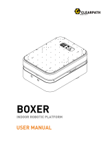
You should not install the sensor at one level with wall protrusions or other objects
that can cause ambiguity when measuring the distance to the wall. Instead, install
the sensor at a height above or below the protrusion to make clear which part of the
building contour the sensor measures.
Figure 2: Sensor installation height at wall protrusions
Consider the following aspects when aligning the sensor horizontally:
•
It should be possible to tilt the sensor mount in all directions in order to be able to
align the sensor horizontally.
•
The scan plane of the sensor shall run parallel to the floor surface.
°
In general, at a scan height of 150 mm, the scanner shall only be pitched by
0.15° in all directions in the field of view of the sensor.
Note: This is important to prevent floor detections, but also to not cause
ambiguity when measuring the distance to the wall at wall protrusions or
other protuded objects.
°
As a minimum requirement, align the sensor with a spirit level or the align‐
ment aid.
•
Align the sensor in an area with an even floor, which is intended for service work.
•
Make sure that the sensor is fixated on a vehicle in such a way that the alignment
of the sensor cannot be changed by accident.
SICK offers an alignment tool: Alignment aid, part number 2101720.
This device uses an internal rechargeable lithium-ion battery and indicates the received
laser beam depending on the beam size by one or more red LEDs.
Further topics
•
"About pose accuracy", page 42
•
"SICK support and further services", page 90
•
"About maps", page 38
•
"Creating a reference map", page 41
3 PRODUCT DESCRIPTION
10
O P E R A T I N G I N S T R U C T I O N S | LiDAR localization software 8024728/19NW/2020-10-22 | SICK
Subject to change without notice

4 User interfaces
Overview
You can control, set and call all localization functions with different user interfaces.
Interfaces
Table 2: Overview of the interfaces
Interface Description
SOPASair Control and setting of most localization functions via the web-interface.
CoLa-A Control and setting of most localization function via telegrams.
UDP Reception of sensor measurement data or pre-processed data of the exter‐
nal vehicle controller via the binary protocol, for example, from 2D-LiDAR
sensor or odometry.
TCP/IP Sending the localization results via the binary output telegram to the exter‐
nal vehicle control
ROS Optional: When using ROS, the interfaces CoLa-A, pre-processed UDP data
and TCP/IP can be replaced with the ROS driver.
Figure 3: Overview of the interfaces
Further topics
•
"User interface SOPASair", page 11
•
"About CoLa-A telegrams", page 70
•
"About odometry for support", page 58
•
"About result port telegrams", page 75
•
"User interface ROS", page 17
4.1 User interface SOPASair
Overview
SOPASair is a web-interface included in the LiDAR-LOC software package and runs on
the localization controller.
USER INTERFACES 4
8024728/19NW/2020-10-22 | SICK O P E R A T I N G I N S T R U C T I O N S | LiDAR localization software
11
Subject to change without notice

Figure 4: Overview of the user interface SOPASair
1
Menu
2
Home
3
History
4
Device Info
5
Software menu
6
User group
7
Main window
8
Setting panels
9
Mouse pointer coordinates
10
Initialization panel
11
Location output panel
Further topics
•
"Logging into SOPASair", page 32
4.1.1 Colors and symbols in SOPASair
Table 3: Colors and symbols in SOPASair
Symbol GUI element Description
Vehicle Vehicle on the map in idle or
localization state.
Vehicle Vehicle on the map, ready for
initial positioning.
Status indicator Reference map is not loaded.
Status indicator Reference map is loaded.
Status indicator Data connection between local‐
ization controller and sensor is
not established.
4 USER INTERFACES
12
O P E R A T I N G I N S T R U C T I O N S | LiDAR localization software 8024728/19NW/2020-10-22 | SICK
Subject to change without notice

Symbol GUI element Description
Status indicator Data connection between local‐
ization controller and sensor is
active.
Status indicator Odometry is inactive and is not
used for localization.
Status indicator Odometry is active but the data
is corrupted.
Status indicator Odometry is active and is used
for localization.
Status indicator Sensor is inactive and is not
used for localization.
Status indicator Sensor is active and is used for
localization.
Switch Function is deactivated.
Switch Function is activated.
Check box Option is not selected.
Check box Option is selected.
Sliding scale Sets a range of values, for
example, the scanning angle.
4.1.2 Viewer window
Viewer window
The viewer displays the reference map and shows the position of the automated guided
vehicle (AGV). Additionally, you can load a different map, check the localization status,
and change viewer settings.
To open the viewer window: Main screen > Viewer
NOTE
Use at least the user level Maintenance display the settings.
USER INTERFACES 4
8024728/19NW/2020-10-22 | SICK O P E R A T I N G I N S T R U C T I O N S | LiDAR localization software
13
Subject to change without notice

Figure 5: Viewer window
Initialization panel
Current X and Y positions of pointer in meters.
Home
Centers the view on the origin of the coordination system.
Initialize pose
Sets the initial pose and automatically adjust the pose to match the
measured scan data in the loaded map. The button is a combined
command of Set pose und Update pose. This is only possible during
localization.
•
Light gray: Initial positioning is inactive.
•
Dark gray: Initial positioning is active, and pose can be
selected.
CoLa-A telegram:
•
LocInitializePose
Set pose
Sets the initial pose.
•
Light gray: Initial positioning is inactive.
•
Dark gray: Initial positioning is active, and pose can be
selected.
CoLa-A telegram:
•
LocSetPose
Update pose
Forces the localization system to update the vehicle position. This is
only possible during localization.
CoLa-A telegram:
•
LocForceUpdate
4 USER INTERFACES
14
O P E R A T I N G I N S T R U C T I O N S | LiDAR localization software 8024728/19NW/2020-10-22 | SICK
Subject to change without notice

Location
X [m] Current position of the vehicle along the X-axis of the map’s coordi‐
nate system.
Y [m] Current position of the vehicle along the Y-axis of the map’s coordi‐
nate system.
Yaw [°] Current orientation of the vehicle with respect to the map’s coordinate
system. 0 means that the vehicle is oriented in positive X-direction.
Pose quality Pose quality of the detected position during localization. Indicates the
stability of the current localization.
There are two values (sensitive and moderate) separately output for
the pose quality in the result port (see "Payload of the result port
telegram", page 77).
•
sensitive: Deviations of the current LiDAR sensor data from the
mapped contour and reflectors have a stronger effect on the
sensitive pose quality. The value adapts more quickly to external
influences, that is, the pose quality can fall as well as rise faster.
•
moderate: Deviations of the LiDAR sensor data from the mapped
contour and reflectors affect the moderate pose quality more
slowly and, with short-term changes, to a lesser extent.
Localization The localization status
•
halted: The localization is off.
•
running: LiDAR-LOC continously calculates the vehicle position.
Inputs
Map Map that is currently loaded. Can be a demo map or a reference map.
Map Loaded Indicates if the selected map is loaded.
•
Map is loaded.
•
Map is not loaded.
LiDAR Data Status of data connection between localization controller and sensor.
Sepcific information is given in Main screen > LiDAR Configuration.
•
Receiving data from all active sensors.
•
Not receiving data from at least one active sensor..
Odometry Data The circle color indicates the status of the received odometry mes‐
sages sent by the vehicle controller.
The function can be activated in Main screen > „Localization Configu‐
ration“.
USER INTERFACES 4
8024728/19NW/2020-10-22 | SICK O P E R A T I N G I N S T R U C T I O N S | LiDAR localization software
15
Subject to change without notice

Receiving odometry messages from the vehicle controller.
Odometry messages are received but not processed by the localiza‐
tion software. The following cases lead to discarded messages:
•
The odometry header or the payload is incorrect. This is for exam‐
ple the case if the wrong number of bytes are sent or the message
type is not an odometry message.
•
The difference between the time stamps of two consecutive odom‐
etry messages is greater than 100 ms.
•
The change in the angular velocity of two consecutive odometry
messages is greater than 10 000 deg/s. Contact SICK support if
your vehicle configuration allows other settings.
Odometry telegrams are not received.
State
Current state The localization state
•
Booting: LiDAR-LOC is not yet ready for operation.
•
Idle: LiDAR-LOC is started. All functions are ready for operation.
•
Localizing: Localization is active. Pose is calculated continuously.
•
DemoMapping: Demo map creation is running.
Localization Select the button to switch localization on or off.
Demo Mapping Select the button to switch demo mapping on or off.
Sensor Data Recorder
Starts the data recording for extended support.
View properties
Follow vehicle Check or uncheck to center the view over the current vehicle’s posi‐
tion.
Used for larger sites or when the vehicle leaves the user’s field of
vision.
Checked: View follows the vehicle and keeps it centered.
Unchecked: View is stationary.
Show scan
points
Check or uncheck to show or hide the scan points on the map.
Checked: Scan points are displayed on the map in red.
Unchecked: Scan points are not displayed on the map.
Further topics
•
"Setting the initial pose manually", page 50
•
"Starting the localization", page 46
4 USER INTERFACES
16
O P E R A T I N G I N S T R U C T I O N S | LiDAR localization software 8024728/19NW/2020-10-22 | SICK
Subject to change without notice

4.1.3 Info window
Overview
The info window gives you the version information for the components of your system.
You can find the info window here: Main screen > Info.
Device info
Figure 6: Info window
Table 4: Device info
Device Type Model name of the localization controller that is currently
connected.
Ident Version Firmware version of the localization controller that is cur‐
rently connected.
Manufacturer Manufacturer of the localization controller.
Firmware Version Firmware version of the localization controller that is cur‐
rently connected.
LLS Version Version of LiDAR-LOC that is currently installed on the local‐
ization controller.
Further topics
•
"Setting the initial pose manually", page 50
•
"Starting the localization", page 46
4.2 User interface ROS
All localization functions can be implemented via the ROS (Robot Operating System)
interface. Therefore ROS must be fully integrated into the vehicle controller of the AGV.
The ROS framework provides software developers with program libraries and tools to
create robot applications. Among other things, it offers a hardware abstraction layer,
device drivers, visualization tools, message exchange functions and a package manage‐
ment. ROS is open source and published under the BSD license.
USER INTERFACES 4
8024728/19NW/2020-10-22 | SICK O P E R A T I N G I N S T R U C T I O N S | LiDAR localization software
17
Subject to change without notice

Figure 7: Überblick ROS-Schnittstelle
You can find the required ROS driver and documentation on GitHub:
https://github.com/SICKAG/sick_lidar_localization
4
USER INTERFACES
18
O P E R A T I N G I N S T R U C T I O N S | LiDAR localization software 8024728/19NW/2020-10-22 | SICK
Subject to change without notice

5 Installation
5.1 Installing the hardware
This document describes the software installation. The following document contains
information about the installation about possible components of LiDAR-LOC:
Table 5: Available documents
Document type Title Part number
Technical notes Hardware integration 8025193
5.2 Deploying the software to the localization controller
Overview
LiDAR-LOC is not pre-installed on the localization controller and must be installed
before usage.
SICK recommends that you regularly update LiDAR-LOC on the localization controller.
SICK supports only the latest software release which can be downloaded
in Support Portal https://supportportal.sick.com/products/localization/lidar-localiza‐
tion/lidar-loc/ in section "Releases".
Important information
NOTICE
By default, the localization controller is a programmable device. When using the local‐
ization controller with the application software LiDAR-LOC, the controller is converted
into an application device. This means that the device cannot be programmed any
longer; it is locked for any additional application and cannot be unlocked.
Prerequisites
•
You are registered at the SICK Support Portal.
•
You have downloaded the current LiDAR-LOC software package LLS-X.X.X.XR.spk
from the SICK Support Portal.
•
You have downloaded the locking file LLSLock.spk.
•
You have downloaded and installed the current SICK AppManager from the SICK
website.
•
The localization controller has a data connection to your desktop computer. Your
desktop computer needs to be in the same subnetwork as the localization con‐
troller, for example, if the localization controller has the IP address 192.168.0.1,
your computer's IP address has to be 192.168.0.X, where X is a number between
2 to 254.
Approach
1. Open the SICK AppManager.
2. In Device search, scan for devices and select the localization controller, for example,
SIM1000 FX.
3. From your download folder, drag and drop the locking file LLSLock.spk to the tab
Firmware.
4. Select Install.
✓
The SICK AppManager installs the locking file LLSLock.spk. The localization con‐
troller is converted into an application device and locked for additional applica‐
tions.
5. Drag and drop the software package LLS-X.X.X.XR.spk from the download folder to
the Firmware tab.
INSTALLATION 5
8024728/19NW/2020-10-22 | SICK O P E R A T I N G I N S T R U C T I O N S | LiDAR localization software
19
Subject to change without notice

Figure 8: Installation of LiDAR-LOC with the SICK AppManager
6. Select Install.
✓
The SICK AppManager installs the software package LLS-X.X.X.XR.spk.
NOTE
If the SICK AppManager stops installation at 0 %, restart the SICK AppManager
and repeat the installation process.
NOTE
If the installation continues to fail, copy all maps that you want to use from
the localization controller to your desktop computer. Delete the maps from the
localization controller and restart the installation process. Copy all maps back to
the localization controller.
7. In SOPASair, open Info.
8. In LLS Version, check if the software version has been updated successfully.
Complementary information
•
Download the firmware LLS-X.X.X.XR.spk and locking file LLSLock.spk here:
https://supportportal.sick.com/products/localization/lidar-localization/lidar-loc/
•
Download the SICK AppManager here:
https://www.sick.com/de/de/softwareprodukte/sick-appspace-software/sick-
appmanager/c/g446551
Next steps
•
"Logging into SOPASair", page 32
Further topics
•
"Info window", page 17
•
"SICK support and further services", page 90
5 INSTALLATION
20
O P E R A T I N G I N S T R U C T I O N S | LiDAR localization software 8024728/19NW/2020-10-22 | SICK
Subject to change without notice
Page is loading ...
Page is loading ...
Page is loading ...
Page is loading ...
Page is loading ...
Page is loading ...
Page is loading ...
Page is loading ...
Page is loading ...
Page is loading ...
Page is loading ...
Page is loading ...
Page is loading ...
Page is loading ...
Page is loading ...
Page is loading ...
Page is loading ...
Page is loading ...
Page is loading ...
Page is loading ...
Page is loading ...
Page is loading ...
Page is loading ...
Page is loading ...
Page is loading ...
Page is loading ...
Page is loading ...
Page is loading ...
Page is loading ...
Page is loading ...
Page is loading ...
Page is loading ...
Page is loading ...
Page is loading ...
Page is loading ...
Page is loading ...
Page is loading ...
Page is loading ...
Page is loading ...
Page is loading ...
Page is loading ...
Page is loading ...
Page is loading ...
Page is loading ...
Page is loading ...
Page is loading ...
Page is loading ...
Page is loading ...
Page is loading ...
Page is loading ...
Page is loading ...
Page is loading ...
Page is loading ...
Page is loading ...
Page is loading ...
Page is loading ...
Page is loading ...
Page is loading ...
Page is loading ...
Page is loading ...
Page is loading ...
Page is loading ...
Page is loading ...
Page is loading ...
Page is loading ...
Page is loading ...
Page is loading ...
Page is loading ...
Page is loading ...
Page is loading ...
Page is loading ...
Page is loading ...
Page is loading ...
Page is loading ...
/