Dacor DO130 Installation guide
- Category
- Ovens
- Type
- Installation guide
This manual is also suitable for

Installation
Distinctive Wall Oven
For usewith models DO130 and DO230
Instructions
Part No. 106732 Rev. D

Important Safety Instructions .......................................... 1
Important Information About Safety Instructions .............. 1
Safety Symbols and Labels ............................................. 1
General Safety Precautions ............................................. 2
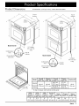
Product Specifications ..................................................... 3
Product Dimensions ......................................................... 3
Installation Specifications ................................................ 4
Electrical Specifications ................................................... 4
Installation Planning ......................................................... 4
Installation Instructions .................................................... 6
Verify the Package Contents ............................................ 6
Remove the Oven Door(s) ............................................... 6
Electrical Connection ....................................................... 7
Installing the Oven in the Cabinet .................................... 9
Reinstalling the Oven Door(s) ........................................ 10
Verifying Proper Operation ............................................. 10
Installation Checklist ....................................................... 11
Notes ................................................................................. 12
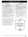
Important:
• Installer: In the interest of safety and to minimize problems, read these installation instructions completely and care-
fully before you begin the installation process. Leave these installation instructions with the customer.
• Customer: Keep these installation instructions for future reference and the local electrical inspector's use.
If You Need Help...
If you have questions or problems with installation, contact
your Dacor dealer or the Dacor Customer Service Team.
For repairs to Dacor appliances under warranty call the
Dacor Distinctive Service line. Whenever you call, have the
model and serial number of the appliance ready. The model
and serial number are printed on the product data label.
Dacor Customer Service
Phone: (800) 793-0093 (U.S.A. and Canada)
Monday -- Friday 6:00 A.M.to 5:00 P.M.Pacific Time
Web site: www.Dacor.com
Dacor Distinctive Service (repairs under warranty only)
Phone: (877) 337-3226 (U.S.A. and Canada)
Monday -- Friday 6:00 A.M.to 4:00 P.M.Pacific Time
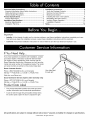
Product Data Label
The product data label contains the model and serial
number information and the electrical specifications.
It can be seen through the grill located directly below
the control panel. Open the door to expose the grill.
View data label
through grill
All specifications are subject to change without notice. Dacor ®assumes no liability for changes to specifications.
© 2009 Dacor, all rights reserved.

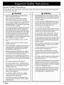
Important Information About
Safety Instructions
The Important Safety Instructions and warnings in
these instructions are not meant to cover all possible
problems and conditions that can occur. Use common
sense and caution when installing, maintaining or oper-
ating this or any other appliance.
• Always contact the Dacor Customer Service Team
about problems and conditions that you don't under-
stand. See Customer Service Information.
Safety Symbols and Labels
[_ DANGER
Immediate hazard s that WILL resu t n severe perso na
injury or death ........................... I
WARNING
Hazards or Unsafe practices that COULD result in severe
personal injury or death.
CAUTION I
Hazards or unsafe practices that COULD result in minor
personal injury or property damage. I
DANGER
IMPORTANT: D0 not store 0r use combustiblel flam1
mable 0r exp!0s!ve vapors and liquids (such as gasoline)
inside orin the vicinity 0f this orany other appliancel Also
keep items that could explode, such as aerosol cans ,
away from the oven_ D0 not store flammable or explosive
materials in adjacent cabinets or areas.
WARNING I
WARNING-NEVER use this appliance as space I
heater to heat or warm the room iDoing so may result in
overheat ng of the app ance.
[_ WARNING
WARNING -NEVER c0ver any sl0tsl holes or passages
in the oven bottom or cover an entire rack with materials
such as aluminum foil. Doing so bl0cks air flow through
the oven and may cause a fire hazard:
[_ WARNING
DO n0t install this appliance outdoors andi0r near Watefl
for examp el near a pool
[_ WARNING
when using the BROIL and CONVECTION BROIL set,
tings, the oven door must be completely shut.
READ AND SAVE THESE INSTRUCTIONS
_mCD_ 1

General Safety Precautions
To reduce the risk of fire, electric shock, serious injury or death when using your appliance, follow basic safety precau-
tions, including the following:
WARNING
, Read the accompanying Use and care manual
before operating this appliancel
• If YOUreceive a damaged product, immediate!Y con-
tact your dealer or builder. DOnot install or use a
damaged appliance: Do not install or use the appli,
once if the conduit is damagedl
• This oven must be properly installed and grounded
bya qualified installer according to these instali
!ation instructions prior tOuse: The instal!dr must
show the customer the location of the circuit break.
er panel or fuse box so that they know Where and
how to turn off electr c power to the oven. Dacor
is n0t responsible for service required to c0rrect a
faulty installati0n. The owner is resp0nsible to make
sure this app! once is properly installed.
• Do not use the door handle(s)to lift or m0ve the
ovenl
A minimum oftw0 pe0ple are required to safe!y
Do not install, repair or replace any part of the oven
unless specifically recommended in the literature
accompanying it! A qualified service technician
shou!d perform all other servicel
; Before performing any type of service or installa,
tion, make sure that the electric power to the oven
is turned off at the circuit breaker or fuse box.
' OnlY use the oven for Cooking tasks expected of a
hOme appliance as outlined in the literature accom,
] ia nliYi::lamv:glit!T :::::::::::::::::::::::::::°vnlit i end r c!omtheme:cia
area around the oven. Do not allow children to pay
the controlsl pull on the hand!e(s) or touch
• Do not store items of interest to children above the
oven, Children could be burned or injured while
climbing on the appliancel
, Do not tamper with the controls, Do not adjust
or alter any part of the oven unless specifica!ly
instructed to do so in this manua.
, Prevent injury due to the unit tipping fo_ard,
secure the oven to the cabinet using the supplied ....
WARNING
• Keep flammable items, such as paper, cardboard,
plastic and cloth away from hot surfaces. Do not put
such items in the oven. Do not allow pot holders to
touch hot surfaces.
• Do not wear loose or hanging apparel while using
the oven. Do not allow clothing to come into contact
with the interior of the oven and the surrounding
areas during and immediately after use.
• Do not use the oven for storage.
• Do not touch the interior surfaces of the oven during
use. After use, make sure these surfaces have had
sufficient time to cool before touching them.
• Do not touch the outside surfaces of the oven dur-
ing the self-clean cycle. They will be hot. Venting
from the oven may cause the trim to become hot.
• For your safety, do not use the oven to cook without
the convection filter installed. When the filter is not
installed, the spinning fan blades at the back of the
oven are exposed.
Non-stick coatings, when heated, can be harmful to
birds. Remove birds to a separate, well-ventilated
room during cooking.
To prevent damage, remove the meat probe from
the oven when it is not being used.
Do not line the oven with aluminum foil or other
materials. These items can melt or burn up during
self-cleaning and cause permanent damage to the
oven.
Do not leave objects that may melt at high tempera-
ture, such as aluminum foil or the meat probe, on
the bottom of the oven.
Do not allow heating elements in the top of the oven
chamber to become covered up by cookie sheets,
aluminum foil, pots, pans, etc. Covering the heating
elements could cause them to over-heat, creating a
fire hazard or damaging the oven.
• Always ensure that the light fixture lens covers are
in place when using the oven. The lens covers pro-
tect the light bulbs from breakage caused by high
oven temperatures or mechanical shock.
2 _mC_

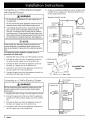
Product Dimensions All tolerances: +1/16 (+1.6 mm), unless otherwise stated.
/_.._/'_ Top of
L chassis
B
C
D
C
D
A
Model DO130
3A"Conduit:
60" (152 cm)
Control panel long
front _l_i _ _T°P of
\-1 I-IT'-I- chassis
Chassis Notch _
Side View
A
Model DO230
Control panel I I_-I I _ o
front _ch '°ps°Ts
Chassis Notch _
Side View
Conduit:
60" (152 cm)
Long
__11/8"
(53.7 cm)
Model
DO130
DO230
Overall
Width (A)
29 3/4"
(75.6 cm)
Chassis
Width (B)
28 3/8"
(72.1 cm)
Overall
Height (C)
28 7/16"
(72.2 cm)
49 15/16"
(126.8 cm)
Chassis
Height (D)*
27 1/2"
(69.9 cm)
49 1/16"
(124.6 cm)
Overlay (E)
15/16"
(2.4 cm)
* To top of chassis notch behind control panel
Utility Utility Utility Control
Notch Chassis Notch
Cutout Cutout Cutout Panel
Width (F) Height (G) Depth (H) Depth (J) Depth (K) Depth (L) Height (M)
5" 5 ¼" 6" 1" 1 5/8" 24" 1"
(12.7 cm) (13.3 cm) (15.2 cm) (2.5 cm) (4.1 cm) (61.0 cm) (2.5 cm)
_m=ar 3

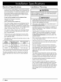
Electrical Specifications
It is the owner's responsibility to ensure that a licensed
electrician performs the installation of the electrical sup-
ply for this appliance. The electrical installation, includ-
ing minimum supply wire size, must comply with the
National Electric Code ANSI/NFPA 70 (latest revision)
and local codes and ordinances.
A copy of this standard may be obtained from:
National Fire Protection Association
1 Batterymarch Park
Quincy, Massachusetts 02269-9101
The correct voltage, frequency and amperage must be
supplied to the appliance from a dedicated, grounded,
single phase circuit that is protected by a properly sized
circuit breaker or time-delay fuse. If a time-delay fuse is
utilized, fuse both sides of the line (L1 and L2).
The required voltage, frequency and amperage ratings
are listed on the product data label (see inside cover)
and in the table below.
• Preheat times and cavity temperature recovery times
will be increased slightly if operating the unit with less
than a 240 Vac circuit.
• This appliance is provided with electrical wiring in a flex-
ible metal conduit.
Model Dedicated Circuit Total Connected
Number Requirements Load
240 Vac 60 Hz,
DO130 4 wire*, 30 Amp. 5.3 kW (23 Amp.)
240 Vac 60 Hz,
DO230 4 wire*, 40 Amp. 7.8 kW (33 Amp.)
Two 120 Vac hot (L1 and L2), one neutral, one ground.
The above specifications are for reference only. See the
product data label (see inside cover) for exact specifica-
tions.
Installation
Planning
WARNING
observe all governing codes and 0rdinances during plan,
ning and installation, Contact your local building depart,
ment for further information. .............
IMPORTANT
Locate the junction box s0 that the oven may be easily
disconnected in the event that it needs to be removed
from the Wall c0mpletely for servicel
, if the oven is not installed !evel it may deliver poor or
inconsistent baking results.
A qualified technician must complete the installation of
this built-in appliance. Proper installation is the respon-
sibility of the customer.
Carefully check the location where the oven is to be
installed. The oven should be placed for convenient
access. Make certain that electrical power, meeting
the Electrical Specifications, can be provided in the
selected location.
• Dacor recommends installing the electrical junction box
in one of the locations shown.
Install the junction box in a location that allows the oven
to be removed from the the cutout for service without
being disconnected.
Plan the installation so that all minimum clearances
are met or exceeded. Dimensions shown provide mini-
mum clearances, unless otherwise noted. Be certain
that proper clearance is provided for the oven door
when it is in the open position according the Product
Dimensions.
The cabinet cutout dimensions must be used as indi-
cated. The specified minimum cabinet depth and width
must be provided. The cabinet depth and width must
completely enclose the recessed portion of the oven.
All contact surfaces between the appliance and the
cabinet must be solid and level.
Provide a platform within the cabinet to support the
oven. It must be installed straight and level, and must
be 24" (61.0 cm) deep. The top edge of the platform
must be flush with the cutout at the front of the cabinet.
There are no provisions to level the oven after it has
been installed. 3/4" (1.9 cm) thick plywood is recom-
mended.
4 _mC_

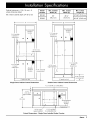
Cabinet tolerances: +1/16 (1.6 mm),-0,
unless otherwise stated.
Min. interior cabinet depth: 24" (61.0 cm)
Model Min. Cabinet Min. Cutout Min. Cutout
Number Width (N) Width (P) Height (R)
DO130 27 5/8" (70.2 cm)
DO230
30"
(76.2 cm)
28 ½"
(72.4 cm)
49 1/8" (124.8 cm)
1" (2.5 cm) Min.
to bottom of
cabinet door
I'
I-
/
I
I
II
1" (2.5 cm) Min.
to top of
cabinet door
Recommended
electrical
location
.\
II
3/4" (1.9 cm)
R support _latform
_/:
Alternate
electrical
location
4" typical toe kick
Single Oven Cabinet Cutout Dimensions
31 1/4" (79.4 cm)
recommended
I" N
1" (2.5 cm) min.
to bottom of
cabinet door
Recommended
electrical
location
\
"1" m
R
3/4" (1.9 cm)
support platform
1" (2.5 cm) Min.
to top of
drawer face
//_/ ............ !,
• t
4" typical toe kick
÷
9 5/8" (24.4 cm)
recommended
Double Oven Cabinet Cutout Dimensions
11/2" T
(3.8 cm) -J
typical counter
36"
(91.4 cm)
1" (2.5 cm) Min. to combustibles
I
I
I
I
I
I
I
I
/
R
P
• I
Recommended
electrical
location
4" typical toe kick
314" (1.9 cm) 1" (2.5 cm) Min.
support platform to combustible floor
Cutout Dimensions - Single Oven Installed Under Counter
_mCD_ 5

Verify the Package Contents
Verify that all the components below have been provided. If any item is missing or damaged, please contact your dealer
immediately. Do not install a damaged or incomplete appliance. Make sure that you have everything necessary to ensure
proper installation before proceeding.
• Product literature
• Mounting screws (wood, #6 X ¾, Dacor PN 83331)
4 for single ovens, 6 for double ovens
• Oven racks, 3 for single ovens, 6 for double ovens
• Meat probe
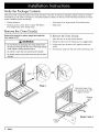
Remove the Oven Door(s)
Remove the door(s) to reduce weight and make the
oven easier to lift:
[_ WARNING
Do not attempt to disengage the hinge catches with
the door(s) removed from the oven, The hinge springs
i could release, causing persona! injury.
DO n0t lift or carry the 0ven do0r(S)bY the handie:
, on double ovens, remove the lower door first to avoid
damagel
To Remove the Oven Door(s)"
1. Open the door to its fully opened position.
2. Rotate the catch over the retaining arm on both hinges.
3. Lift the oven door to about a 30 ° angle from the hori-
zontal.
4. Pull the door away from the oven while continuing to lift.
Catch
Step 2
Grab both sides of the
door and pull out at a 30°
angle to remove.
Gripping
point
Gripping
point
Steps 3 and 4
6 _mC_

Electrical Connection
WARNING
If the electrical service provided does not meet the
Electrical Specifications (see page 4), do not pro-
ceed with the installation. Call a licensed electrician to
correctly install the required wiring.
• Failure to disconnect power prior to installation may
result in an electrical shock or fire hazard.
• Do not turn on power to the appliance until the oven is
propedy grounded according to these instructions.
• The installer must connect the ground terminal (or
lead) on the appliance to a grounded, metallic, perma-
nent wiring system or grounding conductor. Failure to
do so may result in an electric shock hazard.
° Do not install a fuse in the neutral or ground circuit. A
fuse in the neutral or ground circuit may result in an
electric shock hazard.
• The appliance must be connected to the power supply
with copper wire only. The use of aluminum wire may
result in unsatisfactory conditions.
IMPORTANT
'Provide slack in the conduit to allow the oven to slide
fo_ard for servicingl
,The electrical connection leads from the supplied
appliance conduit may bea smaller gage than the
standard household wiring of the dedicated supply cir
cuit They are suitable for c0nnection to househo!d wir.
ing under the jurisdiction of the National Electric Code,
and/or the local inspection authority.
1. Before proceeding, turn off power to the junction box at
the circuit breaker panel or fuse box.
2. Position the oven directly in front of the cabinet cutout.
3. Feed the appliance conduit into the electrical junction
box and attach it using a UL approved strain relief.
4. Depending upon local codes, utilize one of three meth-
ods to connect the appliance to the electrical power:
¢ Connect to a 4-wire electrical system
¢ Connect to a 3-wire electrical system with external
ground, according to local codes.
¢ Connect to a 3-wire electrical system, where local
codes permit
Connecting to a 4-Wire Electrical System
1. Separate the wires coming out of the appliance conduit.
2. Connect the white wire from the appliance conduit to
the white (neutral) supply wire in the junction box.
3. Connect the black wire from the appliance conduit to
the black (L1) supply wire in the junction box.
4. Connect the red wire from the appliance conduit to the
red (L2) supply wire in the junction box.
5. Connect the green wire from the appliance conduit to
the green (ground) wire in the junction box.
Junction box
RED
I_RED
GREEN
_GREEN
Incoming
power
WHITE
WHITE
BLACK
BLACK [_
Wire nut,
4 places
Conduit to
ove n
_mCD_ 7

Connecting to a 3-Wire Electrical System
with External Ground
[_ WARNING
• Do not ground the appliance to a gas supply pipe or
hot water pipe.
• Do not connect the green appliance conduit wire to an
external ground unless local building codes permit.
If connecting the ground wire to a grounded cold water
pipe, connect using a separate copper grounding
wire (No. 10 minimum) and a clamp with an external
grounding screw. The grounded cold water pipe must
have metal continuity to electrical ground and must not
be interrupted by insulating materials. See diagrams.
[_ NOTE
If the junction box has been properly giounded bY a
censed electrician, the appliance green (ground) wire
may be connected tothe junction bOX using a 100p termi-
nal.
To connect the green appliance conduit wire to a
grounded cold water pipe:
,
2.
,
,
,
Separate the wires coming out of the appliance conduit.
Connect the white wire from the appliance conduit to
the white (neutral) supply wire in the junction box.
Connect the black wire from the appliance conduit to
the black (L1) supply wire in the junction box.
Connect the red wire from the appliance conduit to the
red (L2) supply wire in the junction box.
Connect the green wire from the appliance conduit to a
grounded cold water pipe as shown.
,
Jumper any insulating materials as shown at below with
a length of No. 4 copper wire. Securely clamp the wire
to bare metal at both ends.
Separate 10 AWG wire Min.
Incoming L
power I
Junction box
RED
I_RED
[_GREEN
GREEN
tt
#
WHITE
WHITE [_ f
BLACK
BLACK L......J
J Conduit to
oven
iO
Clamp wire
tightly to pipe
Wire nut,
4 places
4 AWG wire Min.
Insulating
device
f
Clamps
Insulated Pipe
Jumper
Bare metal
Connecting to a 3-Wire Electrical System
[_ WARNING I
Donot connect the green appliance c0nduit Wireto the
neutral (white) junction box wire unless local building
Codes permiL
1. Separate the wires coming out of the appliance conduit.
2. Connect the green and white wires from the appliance
conduit to the white (neutral) supply wire in the junction
box.
3. Connect the black wire from the appliance conduit to
the black (L1) supply wire in the junction box.
4. Connect the red wire from the appliance conduit to the
red (L2) supply wire in the junction box.
Junction box
RED
Incoming
power
Conduit to
oven
,/
Wire nut,
3 places
/
8 _mC_

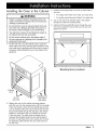
Installing the Oven in the Cabinet
WARNING
• Failure to properly insta I the mounting screws may
result in movement or tipping of the oven during use
resulting in personal injury.
• Do not block the oven air exhaust located at the bot-
tom of the oven. Blocking the intake may result in a
fire hazard, cabinet damage or poor performance.
• The wall oven is heavy. Do not attempt to install it in
the cabinet with less than two people.
• Do not use the exhaust grill or the bottom edge of
the oven opening as a gripping point. Damage to the
exhaust grill may result.
,
Lift the wall oven up to the cabinet cutout, using the
upper edge of the cavity opening and the bottom of the
oven case side as gripping points. Be certain to take all
necessary safety precautions due to the weight of the
appliance.
3. Locate the mounting holes in the trim on both sides of
the oven.
0 For single ovens there are 4 holes, 2 on each side.
0 For double ovens there are 6 holes, 3 on each side.
4. Use a 1/16" drill bit to drill pilot holes in the cabinet
through all of the trim mounting holes.
5. Install all of the provided #6 screws through the oven
trim into the cabinet to secure the oven. Do not over-
tighten the screws.
I
'111 I I I I /11
Mounting Screw Locations
Gripping
point
,
Gripping point:
Do not case bottom
grip here! both sides
Resting the oven on the cabinet mounting platform,
slide the oven into the recessed area until the rear edge
of the oven frame is flush with the cabinet face and the
oven is centered within the cutout. Ensure that the elec-
trical conduit slides through the opening in the cabinet
platform or coils above the oven chassis as the oven
is slid into place. The cable must be placed into the
recessed area located along the rear vertical edge of
the oven or coiled above the oven chassis. Do not trap
the appliance cable between the oven case back and
the rear wall.
_mCD_ 9

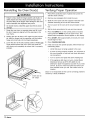
Reinstalling the Oven Door(s)
WARNING
Failure to fully rotate the hinge catches wil! result in
safety hazard and may cause personal inju[y due tO
the door falling off its hinges Also damage t0the OVen
and/or improper door alignment may occur.
, On double ovens, install the upper door first to avoid
damage.
1. Grasp the oven door on opposite sides and lift it until
the door hinges are aligned with the openings in the
oven frame.
,
,
Holding the door at about a 30 ° angle from the horizon-
tal, slide the hinges into the openings until the bottom
hinge arms drop fully into the hinge receptacles.
Lower the door to the fully opened position. Rotate both
hinge catches toward the oven. Open and close the
door slowly and completely to ensure that it is properly
installed.
Insert door at
30 ° angle
Verifying Proper Operation
1. Peel off the protective layer of plastic that covers the
stainless steel surfaces.
,
3.
,
Remove any packaging from inside the oven.
Slide the oven racks onto the supports inside the oven
chamber according to the use and care manual.
Turn on power to the oven at the circuit breaker or fuse
box.
,
6.
,
Set the clock according to the use and care manual.
Press the BAKE key on the control panel (on double
ovens press the BAKE key for the upper oven). The
default bake temperature should appear on the display.
Press START. After approximately 3 minutes, the oven
should begin to heat.
8. Press CANCEL/SECURE.
,
If the oven does not operate properly, follow these trou-
bleshooting steps:
¢ Verify that power is being supplied to the oven.
¢ If power is being properly supplied, turn off power at
the circuit breaker or fuse box and check the electri-
cal connections.
¢ Turn on power and repeat the above heating test.
If the appliance still does not work, contact Dacor
Distinctive Service at (877) 337-3226. Do not
attempt to repair the appliance yourself. If you need
service, be sure to have the model and serial num-
bers available when you call. See inside cover for
location.
Dacor is not responsible for the cost of correcting problems
caused by a faulty installation.
Catch
10 c_acar

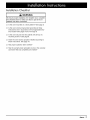
Installation Checklist
WARNING
To ensu[e propel installation; the installer must complete
the checklist below to make sure that no part 0f the in-
stallation has been overlooked: ....................................
[] Is the oven mounted on a level platform? See page 5.
[] Is the oven wired and grounded according to these
instructions and in accordance with all applicable elec-
trical codes? See pages 4 and 7 through 8.
[] Is the oven secured into the cabinet with all four (4)
mounting screws ? See page 9.
[] Is/are the oven door(s) properly installed according to
these instructions. See page 10.
[] Has proper operation been verified?
[] Has the warranty been activated on-line or the warranty
card been filled out completely and mailed?
ctacor 11

12 c_acar

®
Dacor • Phone: (800)793-0093 • FAX: (626)403-3130 • www.Dacor.com
The Life of the Kitchen? American Made*Family Owned
-
 1
1
-
 2
2
-
 3
3
-
 4
4
-
 5
5
-
 6
6
-
 7
7
-
 8
8
-
 9
9
-
 10
10
-
 11
11
-
 12
12
-
 13
13
-
 14
14
-
 15
15


Dacor DO130 Installation guide
- Category
- Ovens
- Type
- Installation guide
- This manual is also suitable for
Ask a question and I''ll find the answer in the document
Finding information in a document is now easier with AI
Related papers
-
Dacor DO130 User manual
-
Dacor PO127AG Installation guide
-
-
Dacor DOC30M977D Series Installation guide
-
-
-
-
-
Dacor MOV230S Installation guide
-
Other documents
-
Summit SEW24SS Installation guide
-
BEA Stainless Steel Angled Mounting Box Template
-
Capital Maestro Series MWOV301ES Installation guide
-
Ledalite VersaForm Recessed Install Instructions
-
KitchenAid 3182137 User manual
-
Ancona AN-2303 User manual
-
Viking Range MVSOE630SS Installation guide
-
Viking MVDOE630BG Operating instructions
-