
IMPORTANT! Please read all information in this manual thoroughly and become familiar with the capabilities and
use of your appliance before attempting to operate or maintain this unit. Pay attention to all safety warnings and
any other special notes highlighted in the manual. Safety markings are used frequently throughout this manual to
designate a degree or level of seriousness and should not be ignored. WARNING indicates a potentially hazardous
situation that if not avoided, could result in personal injury or death. CAUTION indicates a potentially hazardous
situation that if not avoided, may result in minor or moderate injury or property damage. Keep this literature where
you have easy access to it in the future. If a problem occurs, check the instructions and follow recommendations
given. If these suggestions don’t eliminate your problem, call your servicing contractor.
Do not attempt to service this unit yourself! Under no circumstances should the appliance owner attempt to install
and/or service this equipment. Some local codes require licensed installation / service personnel for this type of
equipment. Improper service, adjustment, or maintenance may cause explosion, fire, electrical shock or other
hazardous conditions which may result in personal injury or property damage.
USER’S MANUAL
R6GP-090 ShownR6GN-150 Shown
Single Package Gas Heating / Electric Cooling Rooftop Unit
R6GP-072 (6 Ton), -090 (7.5 Ton), & -120 (10 Ton) Series
R6GN-150 (12.5 Ton) & -180 (15 Ton) Series
DO NOT DESTROY. PLEASE READ CAREFULLY AND KEEP IN A SAFE PLACE FOR FUTURE REFERENCE.
WHAT TO DO IF YOU SMELL GAS
• Donottrytolightanyappliance.
• Do not touch any electrical switch; do not
useanyphoneinyourbuilding.
• Leavethebuildingimmediately.
• Immediately call your gas supplier from a
neighborsphone.Followthegassuppliers
instructions.
• Ifyoucannotreachyourgassupplier,call
theredepartment.
FIRE OR EXPLOSION HAZARD
•Failure to follow safety warnings exactly
could result in serious injury or property
damage.
•Installation and service must be performed
byaqualiedinstaller,serviceagencyorthe
gassupplier.
• Do not store or use gasoline or other
ammablevaporsandliquidsinthevicinity
ofthisoranyotherappliance.
WARNING:
!

2
AbOUT THE ROOFTOP UNIT
This gas heating / electric cooling unit has been
designed and built to provide many years of safe and
dependable comfort, providing it is properly installed
and maintained. With regular maintenance, this unit will
operate satisfactorily year after year. Abuse, improper
use, and/or improper maintenance can shorten the life
of the appliance and create unsafe hazards. A regular
service and maintenance schedule should be established
to ensure efficient and safe operation of the unit. See
System Maintenance on pages 3 - 4.
IMPORTANT SAFETY INFORMATION
WARNING:
To avoid possible equipment damage, re,
or death, the following instructions must be
observedregardingunitlocation,combustion
airrequirements,andoperationalprocedures.
• To achieve optimum performance and minimize
equipment failure, it is recommended that periodic
maintenance be performed on this unit. The ability
to properly perform maintenance on this equipment
requires certain mechanical skills and tools. Please
consult your dealer for maintenance information and
availability of maintenance contracts.
• Theareaaroundthegasheating/electriccoolingunit
and the vicinity of any other gas appliances must be
kept clear and free of combustible materials, gasoline,
and other flammable vapors and liquids. Do not store
or use flammable items such as paint, varnish, or
strippers in the vicinity of the unit.
• Donotusetheareaaroundtheunitasastoragearea.
This area must be kept clean and clear of loose or
exposed insulation materials. Examine the unit’s area
when it is installed or when insulation is added, since
some insulation materials may be combustible.
• Donotusethisapplianceifanyparthasbeenunder
water. Immediately call a qualified service technician
to inspect the unit and to replace any part of the
control system and any gas control which has been
under water.
• Familiarizeyourselfwiththecontrolsthatshutoffthe
gas and electrical power to the unit. If the unit is to be
shut down for an extended period of time, turn off both
thegasandelectricalpower.Foryoursafetyalways
turn off both the gas and electrical power before
performing service or maintenance on the furnace. If
the gas supply must be shut off, refer to the gas valve
label(Figures3or4,pages5-6).
CombustionAirSupply
WARNING:
Combustion air must not be drawn from a
corrosiveatmosphere.
The gas heating/electric cooling unit needs an adequate
supply of combustion and ventilation air for proper and safe
operation. Do not block or obstruct air openings on the unit
or air openings supplying the area where it is installed.
If the unit is operated with inadequate combustion air
supply, the flame roll-out control switch located above
the burners will open, turning off the gas supply to the
burners. The flame roll-out control is a manual reset
device. Do not attempt to reset this device yourself! Call
your servicing contractor.
To maximize heat exchanger life, the combustion air
must be free of chemicals which form corrosive acidic
compounds in the combustion gases.
IMPORTANT NOTE: Do not store any chemicals with
flammable or caustic vapors near the vent termination.
Some examples of these chemicals are:
Ductwork
WARNING:
Failure to prevent products of combustion
frombeingcirculatedintotheoccupiedspace
can create potentially hazardous conditions
including carbon monoxide poisoning that
couldresultinpersonalinjuryordeath.
The duct connections must be physically sound and sealed
to the unit’s casing to prevent products of combustion from
entering the occupied space.
The return air and circulating air ductwork must not be
connected to any other heat producing device such as
a fireplace insert, stove, etc. Doing so may result in fire,
explosion, personal injury, carbon monoxide poisoning,
or property damage.
OPERATING INSTRUCTIONS
Thermostat styles vary. Some models may not include
the AUTO mode and others will have the AUTO in place
of the HEAT and COOL. Others may include all three.
Please refer to the thermostat’s User Manual for detailed
programming instructions.
Thethermostatshouldbemountedabout5feetabovethe
floor on an inside wall and not on an outside wall or other
location where its operation may be adversely affected by
radiant heat from fireplaces, sunlight, or lighting fixtures,
and convective heat from warm air registers or electrical
appliances.

3
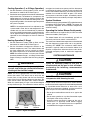
Cooling Operation (1 or 2-Stage Operation)
1. Set the thermostat system mode to COOL and the
thermostatfanmodetoAUTO.SeeFigure1.
2. Set the thermostat temperature selector to the desired
temperature level. The outdoor fan, compressor, and
indoor blower will all cycle on and off to maintain the
indoor temperature at the desired cooling level. On 2
stage cooling models, the second stage compressor
will cycle as required.
NOTE: If the temperature level is re-adjusted, or the
system mode is reset, the fan and compressor in the
outdoor unit may not start immediately. A protective
timer circuit holds the compressor and the outdoor fan
offforapproximately5minutesfollowingaprevious
operation or the interruption of the main electrical
power.
Heating Operation (2 Stage)
1. Set the thermostat system mode to Heat and the
thermostatfanmodetoAUTO.SeeFigure1.
2. Set the thermostat temperature selector to the
desired temperature level. The indoor blower and
gas heat module will cycle on and off to maintain
the indoor temperature at the desired heating level.
NOTE: On some units there is a factory set 3 minute
time delay between Stage 1 and Stage 2 heat when
Stage 2 heating is required. See Unit wiring diagram
label.
WARNING:
Ifoverheatingoccurs,orthegassupplyfailsto
shutoff,shutoffthegasvalvetotheunitbefore
shuttingofftheelectricalsupply.
NOTE: This unit is equipped with a manual-reset flame
roll-out limit switch. This switch acts to verify that the
burner flame is being drawn into the heat exchanger
tubes. If the flame is not being drawn into the tubes, the
flame roll-out switch will open within several seconds.
When this switch opens, the gas valve will de-energize
to stop the flow of gas. The combustion inducer will stay
energized and continue to operate until the thermostat
is satisfied or the switch is closed. Do not reset the flame
roll-out switch before identifying and correcting the fault
condition that caused the switch to open. If the switch
will not reset or continues to open, immediately contact
a qualified serviceman to identify and repair the problem.
SystemShutdown
SetthethermostatsystemmodetoOFFandthethermostat
fanmodetoAUTO.SeeFigure1.NOTE: The system will
not operate, regardless of the thermostat temperature
selector’s setting.
OperatingtheIndoorBlowerContinuously
Set the thermostat fan mode to ON (or CONT on some
thermostatmodels).SeeFigure1.
The indoor blower will start immediately, and will run
continually until the fan switch is reset to AUTO.
The continuous indoor blower operation can be obtained
with the thermostat system switch set in any position,
including OFF. NOTE: The continuous indoor blower
operation is typically used to circulate the indoor air to
equalize a temperature imbalance due to solar loads,
increased occupancy loads, or mechanical equipment
operation.
SYSTEM MAINTENANCE
CAUTION:
Verify all electrical power to the unit is
disconnected and the gas is shut off before
performing the following recommended
maintenance.
CAUTION:
DO NOT touch any of the internal electrical
componentswhilecleaningtheunit.
Proper maintenance is most important to achieve the best
performance from the appliance and should be performed
by a qualified service technician at least once a year.
Followthemaintenance schedule andthe instructions
below for years of safe, trouble free operation.
• Donotplacecombustiblematerialsonoragainstthe
cabinet.
• Donotstoregasolineoranyotherammablevapors
and liquids in the vicinity of the unit.
• Annually inspect the physical support of the unit to
ensure that it is physically sound without sagging,
cracks, gaps, etc., around the base so as to provide a
seal between the support and the base.
Figure1.DigitalThermostat
Fan
Mode
Temperature
Selector
System
Mode

4
• Annuallyinspect the return-airconnection to ensure
that it is physically sound and is still sealed to the
casing of the unit. Also inspect the unit, ductwork, and
vent system for signs of physical deterioration.
• Alwaysreplacethedoorsontheunitafterservicing.
Do not operate the unit without all doors and covers
in place. Avoid operating the unit when windows and
doors are open.
RegularCleaning
• Remove any leaves and grass clippings from the
outdoor coil. IMPORTANT:Becarefulnottodamage
thealuminumns.
• Checkforandremoveanyobstructionssuchastwigs,
sticks, etc.
• Clean the blower compartment regularly during the
heating and cooling seasons to remove any dust
that may have accumulated in the compartment or on
the blower and motor. Buildup of dust on the blower
and motor can create excessive loads on the motor
resulting in higher than normal operating temperatures
and possible shortened service life.
Air Filters
WARNING:
Never operate the unit without a lter in the
returnair system.Dust and lint in thereturn
aircan buildup ontheinternalcomponents,
resulting in loss of efficiency, equipment
damage,andpossiblererisk.
R6GP&R6GNSeries
units are factory equipped with
pleated 2 inch disposable filters. The filters should be
checked periodically and replaced (or cleaned) when
necessary with filters of the same dimensional size.
Replaceusingdisposablelterswithaminimumairow
ratingof500FPMorpermanentltersonly.
IMPORTANT NOTES:
• The lter rack in 6, 7.5 & 10 ton units are eld
adjustable to accommodate 1” permanent lters.
DO NOTuse1”disposableltersintheseunits.
• Always replace the lter access panels after
changingorcleaningthelters.DONOToperate
unitwithoutthelteraccesspanelsinplace.
• Itisveryimportanttoreplaceorcleanthelter(s)
installed in the return air duct of this system. A
cloggedltercouldcauseairowrelatedproblems
and reduce the overall efciency of your unit.
Always replace disposable lter(s) installed in
yoursystemonlywiththesamesizedimensional
ltersthatarebeingreplaced.
• Filters must be ULC approved or equivalent for
useinCanada.
MotorLubrication
The motors for the circulating air blower, outdoor fan, and
combustion blower are pre-lubricated and sealed by the
manufacturer. No further oiling is required for the life of
this product.
BurnerMaintenance
CAUTION:
Somecomponentsintheburnervestibuleare
at high temperatures while the burners are
operating.Usecautiontoavoidpersonalinjury.
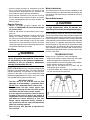
Check the burner flames at the start of every heating
season. Set the thermostat above the room temperature.
Removethecontrolaccesspaneltotheunitandvisually
inspect the burner assembly to make sure that the flame
is drawn directly into the center of the heat exchanger tube
(SeeFigure2).Inaproperlyadjustedburnerassembly,
the flame bends up and to the left at the end of the heat
exchanger tube, and the end of the flame will be out of
sight around the bend. The flame color should be blue,
however some light yellow streaks may occur on the outer
portions of the flame.
TROUbLESHOOTING
Before you call a Technician, check the following:
• Checkthethermostatsetting.Makesurethesystem
mode and temperature settings are correct.
• Checktheelectricalpanelfortrippedcircuitbreakers.
• Checktheltersfordustaccumulation.
• Check the unit and make sure it is clean and not
covered with grass or leaves.
• Iftheitemsabovedon’tresolveyourproblems,then
call your nearest service technician.
Figure2.BurnerInspection

5
A. This appliance does not have a pilot. It is equipped with
an ignition device which automatically lights the burner.
Do not try to light the burner by hand.
B.BEFOREOPERATINGsmellallaroundtheappliance
area for gas. Be sure to smell next to the floor because
some gas is heavier than air and will settle on the floor.
WHATTODOIFYOUSMELLGAS
• Donottrytolightanyappliance.
• Donottouchanyelectricalswitch;donotuseanyphone
in your building.
• Immediatelycallyourgassupplierfromaneighbor’s
phone.Followthegassupplier’sinstructions.
• Ifyoucannotreachyourgassupplier,callthere
department.
C. Use only your hand to push in or turn the gas control
knob. Never use tools. If the knob will not push in or move
by hand, do not try to repair it, call a qualified service
technician.Forceorattemptedrepairmayresultinare
or explosion.
D. Do not use this appliance if any part has been under
water. Immediately call a qualified service technician
to inspect the appliance and to replace any part of the
control system and any gas control which has been
under water.
1. ATTENTION! Lire d’abord la liste des mesures de
sécurité ci-dessus.
2. Mettre le thermostat à la position minimale.
3. Couper le courant électrique qui mène à l’appareil.
4. Cet appareil ménager étant doté d’un système
d’allumage automatique, ne pas essayer d’allumer le
brûleur manuellement.
5.Retirerlepanneau/voletd’accèsdecommande(panneau
supérieurs’ils’agitd’unmodèleàdeuxpanneaux).
6.Fairetournerlerobinetàgazdanslesensdesaiguilles
d’une montre
pourl’amenersurlapositionOFF
(Arrêt)(VoirFigure1).
7.Attendrecinq(5)minutespours’assurerdela
dissipation du gaz.
Encasd’odeur,ARRÊTERLEPROCÉDÉ.Suivreles
instructionsci-dessus(SectionB).Enl’absencede
toute odeur de gaz, avancer à l’étape suivante.
8.Fairetournerlerobinetàgazdanslesensinversedes
aiguilles d’une montre
pour l’amener sur la position
ON(Marche)(VoirFigure1).
9.Remettrelepanneau/voletd’accèsdecommandeen
place (panneau supérieur s’il s’agit d’un modèle à deux
panneaux).
10.Rebrancherl’appareilsurleréseauélectrique.
11. Ajuster le thermostat à la position désirée.
12. Si l’appareil ne fonctionne pas, suivre les “Directives
d’arrêt” cidessous et appeler le technicien de service.
A. Cet appareil ménager n’a pas de veilleuse. II est doté
d’un système d’allumage automatique. Ne pas essayer
d’allumer le brûleur manuellement.
B.AVANTL’USAGE.Attentionàunepossibleodeurde
gaz surtout au niveau du plancher où les gaz les plus
lourds ont la tendance de se concentrer.
ENCASD’ODEURDEGAZ.
• Nemettreenmarcheaucunappareilélectrique.
• Netoucheràaucuncommutateurélectrique,nepas
employer le téléphone.
• Quitterlebâtimentimmédiatementetavertirla
compagnie du gaz en utili sant le téléphone d’un voisin.
• Adéfautdelacompagniedugaz,avertirleservicedes
pompiers.
C. Enfoncer ou faire tourner le robinet à gaz à la main
seulement. Ne jamais utiliser d’outils. S’il n’est pas
possible de faire tourner ou d’enfoncer le robinet à la
main,nepasessayerdeleréparer.Faireappelàun
spécialiste.Forceroutenterderéparerlerobinetpourrait
être à l’origine d’une explosion ou d’un incendie.
D. II est déconseillé d’utiliser cet appareil en contact
prolongéavecl’eau.Faireinspecterouremplacer
toute commande par un technicien qualifié si un des
systèmes de contrôle du gaz s’est trouvé sous l’eau.
1. STOP!Readthesafetyinformationaboveonthis
label.
2. Set the thermostat to the lowest setting.
3. Turn off all electrical power to the appliance.
4. The appliance’s ignition device automatically lights
the burner. Do not try to light burner by hand.
5.Removethecontrolaccessdoor/panel(upperdoorif
two-doormodel).
6.Movethegascontrolknobclockwise
to“OFF”.
(SeeFigure1)
7.Waitve(5)minutestoclearoutanygas.Thensmell
for gas, including near the floor. If you smell gas,
STOP!Follow“B”inaboveinformation.Ifyoudon’t
smell gas, go to the next
step.
8. Move the gas control knob
counterclockwise
to
“ON”.(SeeFigure1)
9.Replacethecontrol
access door/panel (upper
dooriftwo-doormodel).
10.Turnonallelectrical
power to the appliance.
11. Turn the thermostat to a desired setting.
12. If the appliance will not operate, follow the
instructions“ToTurnOffGasToAppliance”andcall
your service technician or gas supplier.
7106750(Replaces710329A)(03/07)
1. Mettre le thermostat à la position minimale.
2. Débrancher l’appareil en prévision de la réparation.
3.Retirerlepanneau/voletd’accèsdecommande(panneau
supérieurs’ils’agitd’unmodèleàdeuxpanneaux).
4.Fairetournerlerobinetàgazdanslesensdes
aiguilles d’une montre
pour l’amener sur la
positionOFF(Arrêt)Nepasforcer(VoirFigure1).
5.Remettrelepanneau/voletd’accèsdecommandeen
place (panneau supérieur s’il s’agit d’un modèle à deux
panneaux).
POUR VOTRE SÉCURITÉ.
À LIRE AVANT L’EMPLOI
FOR YOUR SAFETY READ
bEFORE OPERATING
1. Set the thermostat to the lowest setting.
2. Turn off all electrical power to the appliance if service is
to be performed.
3.Removethecontrolaccessdoor/panel(upperdoorif
two-doormodel).
4. Move the gas control knob clockwise
to“OFF”.Do
notuseforce.(SeeFigure1)
5.Replacethecontrolaccessdoor/panel(upperdoorif
two-doormodel).
ATTENTION!L’inobservationdecesinstructions
peutentraînerunincendieouuneexplosionpouvant
causerdesdammagesàvotrepropriétéàvotre
personne,oulamort.
WARNING:Ifyoudonotfollowtheseinstructions
exactly,areorexplosionmayresultcausingproperty
damage,personalinjury,orlossoflife.
TO TURN OFF
GAS TO APPLIANCE
DIRECTIVES D’ARRÊT
KNOB
( R O B I N E T )
Figure1
MODE D’EMPLOI
OPERATING INSTRUCTIONS
¢7106757¤
Figure3.GasValveLabelfor6TonUnits

6
A. This appliance does not have a pilot. It is equipped with
an ignition device which automatically lights the burner.
Do not try to light the burner by hand.
B. BEFORE OPERATING smell all around the appliance
area for gas. Be sure to smell next to the fl oor because
some gas is heavier than air and will settle on the fl oor.
WHAT TO DO IF YOU SMELL GAS
• Do not try to light any appliance.
• Do not touch any electrical switch; do not use any phone
in your building.
• Immediately call your gas supplier from a neighbor’s
phone. Follow the gas supplier’s instructions.
• If you cannot reach your gas supplier, call the fi re
department.
C. Use only your hand to push in or turn the gas control
knob. Never use tools. If the knob will not push in or move
by hand, do not try to repair it, call a qualifi ed service
technician. Force or attempted repair may result in a fi re
or explosion.
D. Do not use this appliance if any part has been under
water. Immediately call a qualifi ed service technician
to inspect the appliance and to replace any part of the
control system and any gas control which has been
under water.
1. ATTENTION! Lire d’abord la liste des mesures de
sécurité ci-dessus.
2. Mettre le thermostat à la position minimale.
3. Couper le courant électrique qui mène à l’appareil.
4. Cet appareil ménager étant doté d’un système
d’allumage automatique, ne pas essayer d’allumer le
brûleur manuellement.
5. Retirer le panneau/volet d’accès de commande
(panneau supérieur s’il s’agit d’un modèle à deux
panneaux).
6. Réglez l’interrupteur de commande du gaz à la position
“OFF”. (voir Figure 1).
7. Attendre cinq (5) minutes pour s’assurer de la
dissipation du gaz.
En cas d’odeur, ARRÊTER LE PROCÉDÉ. Suivre les
instructions ci-dessus (Section B). En l’absence de
toute odeur de gaz, avancer à l’étape suivante.
8. Réglez l’interrupteur de commande du gaz à la position
“ON”. (voir Figure 1).
9. Remettre le panneau/volet d’accès de commande en
place (panneau supérieur s’il s’agit d’un modèle à deux
panneaux).
10. Rebrancher l’appareil sur le réseau électrique.
11. Ajuster le thermostat à la position désirée.
12. Si l’appareil ne fonctionne pas, suivre les “Directives
d’arrêt” cidessous et appeler le technicien de service.
A. Cet appareil ménager n’a pas de veilleuse. II est doté
d’un système d’allumage automatique. Ne pas essayer
d’allumer le brûleur manuellement.
B. AVANT L’USAGE. Attention à une possible odeur de
gaz surtout au niveau du plancher où les gaz les plus
lourds ont la tendance de se concentrer.
EN CAS D’ODEUR DE GAZ.
• Ne mettre en marche aucun appareil électrique.
• Ne toucher à aucun commutateur électrique, ne pas
employer le téléphone.
• Quitter le bâtiment immédiatement et avertir la
compagnie du gaz en utili sant le téléphone d’un voisin.
• A défaut de la compagnie du gaz, avertir le service des
pompiers.
C. Enfoncer ou faire tourner le robinet à gaz à la main
seulement. Ne jamais utiliser d’outils. S’il n’est pas
possible de faire tourner ou d’enfoncer le robinet à la
main, ne pas essayer de le réparer. Faire appel à un
spécialiste. Forcer ou tenter de réparer le robinet pourrait
être à l’origine d’une explosion ou d’un incendie.
D. II est déconseillé d’utiliser cet appareil en contact
prolongé avec l’eau. Faire inspecter ou remplacer
toute commande par un technicien qualifi é si un des
systèmes de contrôle du gaz s’est trouvé sous l’eau.
1. STOP! Read the safety information above on this label.
2. Set the thermostat to the lowest setting.
3. Turn off all electrical power to the appliance.
4. The appliance’s ignition de
vice automatically lights the
burner. Do not try to light burner by hand.
5. Remove the control access door/panel (upper door if
two-door model).
6. Move the gas control switch to the “OFF” position. (See
Figure 1)
7. Wait fi ve (5) minutes to clear out any gas. Then
smell for gas, including near the fl oor. If you
smell gas, STOP! Follow “B” in
above information. If you
don’t smell gas, go to
the next step.
8. Move the gas control
switch to the “ON”
position. (See Figure 1)
9. Replace the control
access door/panel
(upper door if two-door
model).
10. Turn on all electrical power to the appliance.
11. Turn the thermostat to a desired setting.
12. If the appliance will not operate, follow the instructions
“To Turn Off Gas To Appliance” and call your service
technician or gas supplier.
710674-0 (Replaces 7104030) (03/07)
1. Mettre le thermostat à la position minimale.
2. Débrancher l’appareil en prévision de la réparation.
3. Retirer le panneau/volet d’accès de commande
(panneau supérieur s’il s’agit d’un modèle à deux
panneaux).
4. Réglez l’interrupteur de commande du gaz à la position
“OFF”. Ne forcez pas. (voir Figure 1).
5. Remettre le panneau/volet d’accès de commande en
place (panneau supérieur s’il s’agit d’un modèle à deux
panneaux).
POUR VOTRE SÉCURITÉ.
À LIRE AVANT L’EMPLOI
FOR YOUR SAFETY READ
BEFORE OPERATING
1. Set the thermostat to the lowest setting.
2. Turn off all electrical power to the appliance if service is
to be performed.
3. Remove the control access door/panel (upper door if
two-door model).
4. Move the gas control switch to the “OFF” position. Do
not use force. (See Figure 1)
5. Replace the control access door/panel (upper door if
two-door model).
ATTENTION!
L’inobservation de ces instructions
peut entraîner un incendie ou une explosion pouvant
causer des dam mages à votre propriété à votre
personne, ou la mort.
WARNING: If you do not follow these instructions
exactly, a fi re or explosion may result causing property
damage, personal injury, or loss of life.
TO TURN OFF
GAS TO APPLIANCE
DIRECTIVES D’ARRÊT
MODE D’EMPLOI
OPERATING INSTRUCTIONS
SWITCH
(INTERRUPTEUR)
Figure 1
Figure4.GasValveLabelfor7.5,10,12.5,&15TonUnits


708957A(Replaces7089570&708882A)
WARRANTY INFORMATION
A warranty certificate with full details is included with the equipment. Carefully review these responsibilities with your
dealer or service company. The manufacturer will not be responsible for any costs found necessary to correct problems
due to improper setup, improper installation, adjustments, improper operating procedure on the part of the user, etc.
Some specific examples of service calls which are not included in the limited warranty are:
• Correctingwiringproblemsintheelectricalcircuitsupplyingtheequipment.
• Resettingcircuitbreakersorotherswitches.
• Adjustingorcalibratingofthermostat.
Specications&illustrationssubjecttochangewithoutnoticeorincurringobligations(05/15).
O’Fallon,MO,©NortekGlobalHVACLLC2015.AllRightsReserved.
-
 1
1
-
 2
2
-
 3
3
-
 4
4
-
 5
5
-
 6
6
-
 7
7
-
 8
8


Unbranded R6GN 12.5 - 15 Ton User manual
- Type
- User manual
- This manual is also suitable for
Ask a question and I''ll find the answer in the document
Finding information in a document is now easier with AI
in other languages
Related papers
-
Unbranded R6GP 6, 7.5 - 10 Ton Archived 2/23/12 User manual
-
Nordyne DF6SE 10/31/2011 User manual
-
-
-
Reznor R7TQ Installation guide
-
-
Broan DS4(B,Q)D-KA/KB User manual
-
Westinghouse PSA4BF-KA/B User manual
-
-
Other documents
-
Reznor R6GP User manual
-
Heat Controller RSG1424S1E Owner's manual
-
Reznor JS4BD User manual
-
Reznor R6GN Installation guide
-
-
-
Reznor P6SP User manual
-
Reznor R6GD Installation guide
-
Mammoth R8GE, Single Phase Installation guide
-