Frigidaire FLSG72GCSD Installation guide
- Category
- Tumble dryers
- Type
- Installation guide

Installation
Instructions
Full Size Laundry Center
Gas & Electric
Before beginning installation, carefully read these instructions. This will simplify the installation
and ensure the laundry center is installed correctly and safely. Leave these instructions near the
laundry center after installation for future reference.
NOTE: The electrical service to the laundry center must conform with local codes and ordinances
and the latest edition of the National Electrical Code, ANSI/NFPA 70, or in Canada, CSA C22.1
Canadian Electrical Code Part 1.
NOTE: The gas service to the laundry center must conform with local codes and ordinances and
the latest edition of the National Fuel Gas Code ANSI Z223.1 or in Canada, CAN/CGA B149.12.
NOTE: The laundry center is designed under ANSI Z21.5.1 or ANSI/UL 2158 - CAN/CSA C22.2
(latest edition) for HOME USE only. This laundry center is not recommended for commercial
applications such as restaurants or beauty salons, etc.
For your safety the information in
this manual must be followed to minimize the risk
of fire or explosion or to prevent property damage,
personal injury or loss of life.
ll_e aa_...,lne or
- DO not store or < ._q,,r other flammable
vapors and liquid in the vicinity ol this or any
other appliance.
- WHAT TO DO IF YOU SMELL GAS
• Do not try to light any appliance.
• Do not touch any electrical switch; do not use
any phone in your building.
• Clear the room, building or area of all
occupants.
• Immediately call your gas supplier from a
neighbor's phone. Follow the gas supplier's
instructions.
• If you cannot reach your gas supplier, call the
fire department.
Installation and service must be performed by a
qualified installer, service agency or the gas
supplier.
_rinted in U.S.A.
Contents
SUBJECT
Pre-lnstallation Requirements
Electrical Requirements
Drain Requirements
Exhaust System Requirements
GasSupply Requirements
Location
Mobile Home Installation
Rough-In Dimensions
Unpacking
Electrical Installation
Grounding Requirements
3 & 4-Wire Connections
Installation
Replacement Parts
PAGE
2
2
2
2
3
4
4
4
5
5
6
6
7
7
8
PiN134182900 (0212)

PRE-INSTALLATION REQUIREMENTS
Tools and Materials Required for Installation:
I. Phillips head screwdriver.
2. Channel-lock adjustable pliers.
3. Carpenter's level.
4. Flat or straight blade screwdriver.
5. Duct tape.
6. Rigid or flexible metal 4 inch (10.16 cm) duct.
7. Vent hood.
8. Pipe thread sealer (Gas).
9. Ratchet with 318 inch (0.96 cm) socket.
ELECTRICAL REQUIREMENTS
ELECTRICLaundry Center
CIRCUIT - Individual 30 amp branch circuit fused with 30 amp
minimum time delay fuses or circuit breakers.
POWER SUPPLY- 3-wire or 4-wire, 240 volt, single phase, 60
Hz, Alternating Current.
POWER SUPPLYCORD KIT- The laundry center MUST employ
a 3-conductor power supply cord NEMA 10-30 type SRDTrated
at 240 volt AC minimum, 30 amp, with 3 open end spade lug
connectors with upturned ends or closed loop connectors OR
a 4-conductor power supply cord NEMA 14-30 type SRDTor
ST(asrequired) rated at 240 volt AC minimum, 30 amp, with 4
open end spade lug connectors with upturned ends or closed
loop connectors and marked for usewith clothes dryers. If being
installed in a manufactured (mobile) home, the laundry center
MUST employ a 4-conductor power supply cord NEMA t4-30
type SRDTor ST(as required) rated at 240 volt AC minimum,
30 amp, with 4 open end spade tug connectors with upturned
ends or closed loop connectors and marked for usewith clothes
dryers. See ELECTRICAl..CONNECTIONS. (Canada - 4-wire
power supply cord is installed on laundry center.)
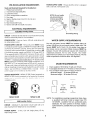
OUTLET RECEPTACLE- NEMA I0-30R (3-wire) receptacle or
NEMA 14-30R (4-wire) receptacle to be located so the power
su{py <o_c!i (c,,,iil_ when I'..- lamdy (erq'r F _
installed position.
NEMA 10-30R
NEMA 14-30R
GAS Laundry Center ]
CIRCUIT - Individual 15 amp branch circuit fused with a 15
amp maximum time delay fuse or circuit breaker.
POWER SUPPLY - 3 wire, 120 volt single phase, 60 Hz,
Alternating Current.
POWER SUPPLY CORD - The gas laundry center is equipped
with a 120 volt 3-wire power cord.
NOTE: Do not under
any circumstances
remove grounding
prong from plug.
Grounding Prong
WATER SUPPLY REQUIREMENTS
Hot and cold water faucets MUST be installed within 42
inches (t06.68 cm) of your laundry center's water inlet. The
faucets MUST be 3/4 inch (1.9 cm) garden hose type so
inlet hoses can be connected. Water pressure MUST be
between 10 and 120 pounds per square inch (maximum
unbalance pressure, hot vs. cold, 10 psi). Your water
department can advise you of your water pressure. The hot
water temperature should be about 140 degrees R
DRAIN REQUIREMENTS
1. Drain capable of eliminating 17 gals. per minute.
2. A standpipe diameter of 1-t/4 inches (3.t8 cm) minimum.
3. The standpipe height above the floor should be:
Minimum height: 33 inches (83.82 cm)
Maximum height: 96 inches (244 crn)
I"
33" Min.
(83.82 cm
1"
96" Max.
(244 cm)
NOTE: For installations requtrmg a longer drain hose, have
a qualified technician install a longer hose PIN
131461201, available from an authorized parts
distributor. For drain systems in the floor, install a
siphon break kit, available from your local hardware
store.

EXHAUST SYSTEM REQUIREMENTS
Use only 4 inch (10.16 cm) diameter (minimum) rigid or flexible
metal duct and approved vent hood which has a swing-out
damper(s) that opens when the dryer is in operation. When the
dryer stops, the damper(s) automatically closes to prevent drafts
and the entrance of insects and rodents. To avoid restricting the
outlet, maintain a minimum of 12 inches (38.5 cm) clearance
between the vent hood and the ground or any other obstruction.
The following are specific requirements for
proper and safe operation of your laundry center, Failure to
follow these instructions can create excessive drying times
and fire hazards.
[] Do not use plastic flexible duct to exhaust the dryen Excessive
lint can build up inside the exhaust system and create a fire hazard
and restrict air flow. Restricted air flow will increase drying times.
If your present system is made up of plastic duct or metal foil
duct, _lace it with a rigid or flexible metal duct. Ensure the
present duct is free of any lint prior to installing laundry
center dryer duct.
[] If the_Ly_r is not exhausted outdoors, some fine lint will be
_ed into the Iaundr£area= An accumulation of lint in any area
of the home can create a health and fire hazard. The dryer
exhaust system MUST he exhausted to the outside of the
dwelling!
[] Do not allow combustible materials (for example: clothing,
draperiedcurtains_aper) to come in contact with the exhaust
s._ The dryer MUST NOT be exLlausted into a chimney, a
wall, a ceiling, or any concealed space of a building which can
accumulate tint, resulting in a fire hazard.
[] Do not exceed the le__h__e or number of elbows
allowed in the "EXHAUST DUCT LENGTHS"chart. Lint can
accumulate in the system, plugging the systern and creating a fire
hazard, aswell asincreasing drying dmes
_l_Do not screen the exhaust ends of the vent system, nor use
a_crews or rivets to assemble the exhaust system. Lint can
become cauqht in the screen, on the screws or rivets, clogging
drying times. Use an approved vent hood to terminate the duct
outdoors, and seat all joints with duct tape. All male duct pipe
fittings MUST be installed downstream with the flow of air.
Explosion hazard. Do not install the dryer where
gasoline or other flammables are kept or stored. If the dryer is
installed in agarage, it must be a minimum of 18 inches (45.7 cm)
above the floor. Failureto do so can result in death, explosion, fire
or burns.
t. The exhaust systemback pressure MUST not exceed 0.6 inches
(! .52 cm) of water column, measured with an inclined
manometer at the point the exhaust connects to the dryer.
. The exhaust system should be inspected and cleaned a
minimum of every two years with normal usage. The more
the dryer isused, the more often you should check the exhaust
system and vent hood for proper operation.
The maximum length of the exhaust system depends upon
the type of duct used, number of elbows and type of exhaust
hood.
Themaximum length for both rigid and flexible duct isshown
in the chart below.
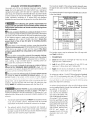
EXHAUST DUCT LENGTHS
EXHAUST HOOD TYPE
of 90_ _
Turrts 140_2
MAXIMUM LENGTH OF 4-INCH 110,2 CM)
DIAMETER RIGID METAL DUCT
0 56 ft. (17.07 m) 42 ft. (128 m)
1 46ft. (14.02 m) 36 ft.(10 97 m]
2 34 ft. (10.36 m) 28 ft. (8.53 m)
3 32 ft. (9.75 m) 18 ft (5.48 m)
MAXIMUM LENGTH OF 4-INCH 110.2 CM)
DIAMETER FLEXIBLE METAL DUCT
0
I
2
3
30ft.(9.]4m)
22 ft.(67m)
16ft (488m)
10 ft,(3OSm)
22 ft (67 m)
14ft 1427 m)
10 ft. (305m
5 ft 115 m)
The laundry center may be exhausted four (4) ways with
rear flush installation:
1. Straight back.
2. Down (8 inch (20.32 cm) length of 4 inch
rigid duct and I elbow down).
3, Left (8 inch (20.32 cm) length of 4 inch
4.
10.16 cm)
10.16 cm)
rigid duct, 1 elbow down and 1 elbow left).
Right (8 inch (20.32 cm) length of 4 inch (10.16 cm)
rigid duct, t elbow down and 1 elbovv right).
To exhaust up, add an 11 inch (27.94 cm) length of standard
4 inch (I0.!6 cm) diameter duct and a 90° elbow. The unit
_i' I_<Do ! :r*'.d _:ho _' ir_che 111 43 (rn),_vva\ [f,,r
ibe wa[i (1lush to wall exhausting may be done by going
below the dryer then sideways).
An exhaust hood positioned to line up with the dryer exhaust
can be installed directly through the outside wall. Toexhaust
up, add an 1! inch (27.94
cm) length of standard 4 "_-
inch 110.16 cm) diameter
duct and a 90 ° elbow. The
unit will be positioned about
4V2inches (11.43 cm) away
from the wall (flush to wall
exhausting may be done by
going below the dryer then
sideways). Toexhaust to the
side or down, add an 8 inch -..
(20.32 cm) length of
standard 4 inch 110.16 cm)
diameter duct and a 90 °
elbow.

GAS SUPPLY REQUIREMENTS
1. Installation MUST conform with local codes, or in the
absence of local codes, with the National Fuel Gas Code,
ANSI Z223.1 (latest edition) or in Canada, the current
CAN/CGA B149.
2. The gas supply line should be of 1/2 inch (1.27 cm) pipe.
3. Ifcodes allow, flexible metal tubing may be usedto connect
your dryer to the gas supply line. The tubing MUST be
constructed of stainless steel or plastic-coated brass.
4. The gassupply fine MUST havean individual shutoff valve.
5. A 1/8 inch (0.32 cm) N.RT. plugged tapping, accessible
for test gage connection, MUST be installed immediately
upstream of the gas supply connection to the dryer,
6. The dryer and its individual shutoff valve MUST be
disconnected from the gas supply piping system during
any pressure testing of the gas supply piping system at
test pressures equal to or lessthan 1/2 psig (3.45 kPa).
7. The dryer MUST be isolated from the gas supply piping
system byclosing its individual manual shutoff valve during
any pressure testing of the gas supply piping system at
test pressuresequal to or less than t/2 psig (3.45 kPa).
LOCATION OF YOUR LAUNDRY CENTER
DO NOT INSTALL YOUR LAUNDRY CENTER:
1. In an area exposed to dripping water or outside weather
conditions.
2. In an area where it will come in contact with curtains or
drapes.
3. On carpet. Floor MUST be solid with a maximum slope of
1 inch(2.54 cm).
INSTALLATION IN RECESSOR CLOSET
I. A laundry center installed in abedroom, bathroom, recess
or closet, MUST be exhausted outdoors.
2. NOother fuel burning appliance shall be installed in the
same closet asthe Gas laundry center.
3 Your taundry center needs the space around it for proper
ve_ [liL]tlo[
DO NOT INSTALL YOUR LAUNDRY CENTER IN A
CLOSETWITH A SOLID DOOR.
4. A minimum of 120 square inches (774.2 square cm) of
opening, equally divided at the top and bottom of the
door, is required. Air openings are required to be
unobstructed when a door is installed. A touvered door
with equivalent air openings for the full length of the door
isacceptable.
6_0SQ, IN.
(387,1 5Q. CM)
T
0
(387,1 SQ, CM)
CLOSET DOOR
.
4
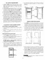
The following illustrations show minimum clearance
dimensions for proper operation in a recess or closet
installation.
0 IN.
(o CM)
!_ _ THI I[ i I
WASHER
T
SIDE VIEW
MOBILE HOME INSTALLATION
1. Dryer MUST be exhausted outside (outdoors, not beneath
the mobite home) using metal ducting that will not support
combustion. Metal ducting must be 4 inches (10.16 cm)in
diameter with not obstructions. Rigidmetal duct ispreferred.
2. If dryer is exhausted through the floor and area beneath
the mobile home is enclosed, the exhaust system MUST
terminate outside the enclosure with the termination
securely fastened to the mobile home structure.
3. Refer to page 3 for other important venting requirements.
F
7
4. When installing a gas dryer into a mobile home, aprovision
must be made for outside make up air. This provision is to
be not lessthan twice the area of the dryer exhaust outlet.
5. Installation MUST conform to current Manufactured Home
Construction & SafetyStandard (which isa FederalRegulation
Title 24 CFR-Part 32-80) or when such standard is not
applicable, with American National Standard for Mobile
Homes. tn Canada, the CSA Z240 is applicable.
The laundry center is designed under ANSI Z
21.5.1 for HOME USE only.

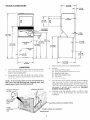
ROUGH-IN DIMENSIONS (64.13CM)
.2-1/2 iN.
(6.35 CM)
75-1/2 IN.
(191, 7 CM)
54-5/16 IN.
(137.95 CM)
r
0
WATER INLETS j'
(REAR)
DRAIN OUTLE"
(REAR)
l
33/4 IN,
_c- (9.52 CM)
27 iN.
(68.58 CM)
16-1/4 IN.
(41.27 CM)
t
GAS SUPPLY
5-1/4 IN.l [
(13,33
CM) 6_
41 1! 43 IN.
- 4IN (109.22CM)
,.j.(,o,.77ca,
(74.77 CM) 3
(91,60 CM)
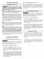
UNPACKING
!. Usingthe four shipping carton corner posts (two on each
side), carefully lay the laundry center on its left side and
remove foam shipping base.
2. Using ratchet with 3/8 inch (0.96 cm) socket, remove
mechanism shipping bolt and plastic spacer block from
NOTE: If the laundry center is to be transported at a
later date, the tub blocking pad, shipping bolt, and
plastic spacer block should be retained.
SHIPPING BLOCKS
47 IN.
(119,38 CM)
PLASTIC SPACER
BLOCK
30_13/16 IN.
(78.26 CM) --
1-7!8 IN.
(4.76 CM)
_ 4-13116 IN.
(12.22 CM)
11-7l 16 IN.
(29.05 CM)
,
4.
5,
.
Return laundry center to an upright position,
Remove:
Ca) foam tub blocking pad.
(b) foam shipping blocks from rear of unit,
(c) tape from dryer door.
(d) foam dryer support pads.
(e) inlet hoses.
From the back of the washer, remove the wire shipping
clips securing the drain hose and power cord (if
equipped). Plastic clamps secure the drain hose to the
right side of the washer backsheet. These clamps form a
standpipe to prevent water syphoning. DO NOT
REMOVE THESE CLAMPS.
Carefully move the laundry center to within 4 feet
(1,22 m) of the final location for the start of the
installation.
MECHANISM
SHIPPING
BOLT
_PING CARTON CORNER POSTS
FOAM
SHIPPING
PAD
POWER CORD (tF EQUIPPED)
DRAIN HOSE
5

ELECTRICAL INSTALLATION
Fora permanently connected laundry center:
ALL ELECTRIC Laundry Centers J
The following are specific requirements for
proper and safe electrical installation of your laundry
center. Failure to follow these instructions can create
electrical shock and/or a fire hazard.
[] This appliance MUST be DroDerlvorounded. Electricalshock l
can result if the laundry center isnot properly grounded. Follow
l
the instructions in this manual for proper grounding.
[] DOnot usean extension cord with this laundrv center. Some
extension cords are not designed to withstand the amounts of
electrical current this laundry center utilizes and can melt,
creating electrical shock and/or fire hazard. Locate the laundry
center within reach of the receptacle for the length power cord
to be purchased, allowing some slack in the cord, Refer to the
pre-installation requirements in this manual for the proper
power cord to be purchased.
[] A U.L approved strain relief must be installed onto Dower
cord. If the strain relief isnot attached, the cord can be pulled
out of the laundry center and can be cut by any movement of
the cord, resulting in electrical shock.
[] Do not use an aluminum wired receptacle with a copper
wired power cord and pIuq (or vice versa).A chemical reaction
occurs between copper and aluminum and can cause electrical
shorts. The proper wiring and receptacle isa copper wired
power cord with a copper wired receptacle OR aluminum
wired power cord with an aluminum wired receptacle,
NOTE: Laundry centers operating on a 208 volt power supply
will have longer drying times than laundry centers operating
on a 240 volt power supply.
GROUNDING REQUIREMENTS
i iron-Canadian [:LI:CT,RI(. Laul_r¥ Lenl.e_ i
_ tmproper connection of the equipment
grounding conductor can result in a risk of electrical shock.
Check with a licensed electrician if you are in doubt as to
whether the appliance is properly grounded.
The laundry center MUST be connected to a grounded metal,
permanent wiring system; or an equipment grounding
conductor MUST be run with the circuit conductors and
connected to the equipment-grounding terminal or lead on
the appliance.
Canadian ELECTRICLaundry Center J
Improper connection of the equipment
grounding conductor can result in a risk of electrical shock.
Check with a licensed electrician if you are in doubt as to
whether the appliance is properly grounded.
Fora arounded cord connected laundry center:
I.
The laundry center MUST be grounded. In the event of
malfunction or breakdown, grounding will reduce the risk
of electrical shock by providing a path of least resistance for
the electrical current.
.
Sinceyour laundry center isequipped with a power supply
cord having an equipment-grounding conductor and a
grounding plug, the plug MUST be plugged into an
appropriate outlet that is properly installed and grounded in
accordance with all codes and ordinances. If in doubt, call a
licensed electrician.
I
1.
All GAS Laundry Centers
The laundry center, when installed, MUST be electrically
grounded in accordance with local codes, or in the absence
of local codes,with the National Electrical Codes, ANSI!NFPA
(latest edition) or in Canada, CSAC22.1 Canadian Electrical
Code Part 1.
Je iat _d (t_nt_ : equipped wii _ th u I)r(it
(grounding) plug for your protection against shock hazard
and should be plugged directly into a properly grounded
three-prong receptacle. Do not cut or remove the grounding
prong from this plug.
For a qrounded cord-connected laundry center:
I. The laundry center MUST be grounded. In the event of
malfunction or breakdown, grounding will reduce the risk
of electrical shock by a path of least resistance for electrical
current.
2. If your laundry center isequipped with a power supply cord
having an equipment-grounding conductor and a grounding
plug, the plug MUST be plugged into an appropriate, copper
wired receptacle that is properly installed and grounded in
accordance with all local codes and ordinances. If in doubt,
call a licensed electrician.

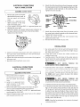
ELECTRICAL CONNECTIONS
FOR A 3-WIRE SYSTEM
ELECTRIC Laundry Center
6. Attach the white (neutral) wire from the power cord and
the green ground wire from the appliance harness to the
silver-colored center terminal on the terminal block.
Tighten the screw securely.
1, Remove the screw securing the
terminal block access cover to
the rear panel and remove
cover.
2. Install a U.L approved strain
relief connector in the entry
hole on the back panel.
3. Insert a NEMA 10-30 Type SRDT, U.L approved power cord
through the strain relief.
4, Attach the power cord neutral (central wire) conductor to
the silver colored center terminal on the terminal block.
Tighten the screw securely.
/
5. Attach the remaining two power cord outer conductors to
the outer brass colored terminals on the terminal block.
Tighten both screws securely_
6. Tighten the screws securing the cord restraint firmly against
the power cord.
7_ Reinstall the terminal block accesscover.
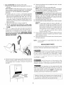
ELECTRICAL CONNECTIONS
FOR A a-WIRE SYSTEM
ELECTRICLaundry Center
1
1. Removethe screw securing the
terminal block access cover to
the rear panel and remove
cover.
2. Install a U,L.approved strain
relief connector in the entry
hole on the back panel.
7
3. Remove the green neutral ground wire from the green
ground screw located above the terminal block.
4. Insert a NEMA 14-30 Type STor SRDT,U.L approved power
cord through the strain relief.
5. Attach the green power cord ground wire to the cabinet
with the green ground screw.
Gsc_wn Ground
Greei_
Con
(Cord)
Ground Red--
Wire
llver Terminal
erminal Block
Black
,White
7. Attach the red and black wires from the power cord to
the outer brass-colored terminals on the terminal block.
Tighten both screws securely.
8. Tighten the screws securing the cord restraint firmly
against the power cord.
9. Reinstall the terminal block accesscover.
INSTALLATION
!. Run some water from the hot and cold faucets to flush
the water lines and remove particles that might clog up
the water valve screens.
2. Check inlet hoses to ensure the rubber washers are
installed in each end.
3. Carefully connect the inlet hoses to the water valve (on
the left side of the washer cabinet), tighten by hand, then
tighten another 2/3 turn with pliers,
4.
.
6.
_DO NOT CROSS THREAD OR
OVERTIGHTEN THESE CONNECTIONS.
Determine which water faucet is the HOT water faucet
and careful!v connect the bottom inlet hose to the HOT
vvate_ i_uce[, lighten by i_ano, iheri tighten anoiJiei 2/..
turn with pliers. Carefully connect the top inlet hose to
the COLD water faucet, tighten by hand, then tighten
another 2/3 turn with pliers.
_DO NOT CROSS THREAD OR
OVERTIGHTEN THESE CONNECTIONS, Turn the water
on and check for leaks at both connections.
Carefully move the laundry center to its final location.
To ensure the laundry center is level and solid on all four
legs, tilt the laundry center forward so the rear legs are
off the ground. Gently set the laundry center back down
to allow the rear legsto self adjust. Placea level on top of
the washer. Check it sideto side, then front to back. Screw
the front leveling legs up or down to ensure the laundry
center is resting solid on all four legs (no rocking of the
laundry center should exist).
NOTE: Keep the leg extension at a minimum to prevent
excessivevibration.

7. GAS CONNECTION (Gaslaundry centers only)
a. Remove the shipping cap from gas pipe at the rear of
the dryer,
NOTE: DO NOT connect the laundry center to natural gas
service without converting the gas valve. A natural gas
conversion kit must be installed bya qualified gas
technician.
b. Connect a 1/2 inch (1.27 cm) I.D. semi-rigid or approved
pipe from the gas supply line to the 3/8 inch (0.96 cm)
pipe located on the back of the dryen Use a 1/2 inch
(I.27 cm) to 3/8 inch (0.96 cm) reducer for the
connection. Apply an approved thread sealer that is
resistant to the corrosive action of liquefied gases on all
pipe connections.
c. Open the shutoff valve in the gas supply line.
d. Test all connections by brushing on a soapy water
solution. NEVERTESTFORGAS LEAKSWITH AN OPEN
FLAME.
8. Form a "U" shape on the end of the drain }-losewith tile
hose pointed toward the drain. Placethe formed end in a
laundry tub or a standpipe and secure with a cable tie
provided in the enclosure package. WATERWILL SYPHON
FROM THE WASHER IF THE ABOVE INSTRUCTIONS
ARE NOT FOLLOWED.
Cable
Tie
9. Remove the two (2) screws securing the dryer front access
panel to the dryer cabinet. Lift the panel until the tabs can
be disengaged from the cabinet. Remove the panel and
set aside.
10. Connect the exhaust duct to outside duct work. Use duct
tape to seal all joints.
11. Plug the power cord into a grounded outlet.
NOTE: Check to ensure the power isoff at acircuit breaker/
fuse box before plugging the power cord into an outlet.
12. Turn on the power at a circuit breaker/fuse box.
_ Before operating the dryer, make sure the
dryer area is clear and free from combustible materials,
gasoline, and other flammable vapors. Also see that
nothing (such as boxes, clothing, etc.) obstructs the flow
of combustion and ventilation air
13. Reinstall the dryer front access panel.
14. Runthe washer and dryer through a cycle. Check for proper
operation.
NOTE: On gas dryers, before the burner will light, it is
necessary for the gas line to be bled of aic If the
burner does not light within 45 seconds the first
time the dryer isturned on, the safety switch will
shut the burner off. If this happens, turn the timer
to "OFF" and wait 5 minutes before making
another attempt to light.
15. If your laundry center does not operate, please review the
"Avoid Service Checklist" located in your Owner's Guide
before calling for service.
16. Placethese instructions in a location nearthe laundry center
forfuture reference.
NOTE: A wiring diagram is located behind the dryer front
accesspanel.
REPLACEMENT PARTS
If replacement parts are needed for your laundry center, contact
the source where you purchased your laundry center.
__ Destroy the carton, plastic bags, and metal band
after the laundry center isunpacked. Children might usethem
for play. Cartons covered with rugs, bedspreads, or plastic
_hee!_can becom_ airtight chambers causing suffocatk)n Place
ai iiia[eli8i; [ a garbage contame[ or make niokelioi5
inaccessible to children.
Label all wires prior to disconnection when
servicing controls. Wiring errors can cause improper and
dangerous operation. Verify proper operation after servicing.
The instructions in this manual and all other
literature included with this laundry center are not meant to
cover every possible condition and situation that may occur.
Good safe practice and caution MUST be applied when
installing, operating and maintaining any appliance.
Access
Panel
Screws
Maximum benefits and enjoyment are achieved when all
the Safety and Operating instructions are understood and
practiced as a routine with your laundering tasks.
8
-
 1
1
-
 2
2
-
 3
3
-
 4
4
-
 5
5
-
 6
6
-
 7
7
-
 8
8


Frigidaire FLSG72GCSD Installation guide
- Category
- Tumble dryers
- Type
- Installation guide
Ask a question and I''ll find the answer in the document
Finding information in a document is now easier with AI
Related papers
-
Frigidaire FARG1011MW2 Installation guide
-
Frigidaire FARG1011MW Installation guide
-
Frigidaire FFRE1001PW Installation guide
-
Frigidaire FLXG52RBSA Installation guide
-
Frigidaire FFLE3900UW Installation guide
-
Crosley SWXG831HS2 Installation guide
-
Frigidaire FAQG7072LW0 Installation guide
-
Crosley FAQG7011LB0 Installation guide
-
Universal/Multiflex (Frigidaire) GCET1031FS4 Installation guide
-
Frigidaire FAQG7001LW0 Installation guide
Other documents
-
Kenmore 41797822700 Installation guide
-
Kenmore 41797912702 Installation guide
-
Crosley CDG7700LW0 Installation guide
-
GE 134996600B (0711) User manual
-
-
-
Crosley CDE4700LB0 Installation guide
-
Maytag MDE6700AYW Installation guide
-
-
Haier CGDE 450 AW User manual