Page is loading ...

CONTROL THERMOSTAT
THERMOSTAT
THERMOSTAT DE CONTRÔLE
RAYSTAT-CONTROL-10

2 | nVent.com
ENGLISH
Table of contents ......................................................................................... 2
Description & Technical data ....................................................................... 6
Functional description ................................................................................. 7
Display .......................................................................................................... 7
Installation description ................................................................................ 8
Operational description ............................................................................. 11
Testing, commissioning and maintenance .............................................. 15
Wiring diagrams ......................................................................................... 37
Commissioning sheet ................................................................................ 39
DEUTSCH
Inhaltsverzeichnis ....................................................................................... 2
Beschreibung & technische Daten ............................................................ 16
Funktionsbeschreibung ............................................................................. 17
Display ........................................................................................................ 18
Montage ...................................................................................................... 18
Programmierung ........................................................................................ 22
Test, Inbetriebnahme und Wartung ........................................................... 25
Anschlussdiagramme ................................................................................ 37
Inbetriebnahmeprotokoll ........................................................................... 39
FRANÇAIS
Table des matières ...................................................................................... 2
Description & caractéristiques techniques .............................................. 26
Fonctionnement ......................................................................................... 27
Afficheur ..................................................................................................... 28
Installation .................................................................................................. 29
Paramétrage ............................................................................................... 33
Test, mise en service et entretien ............................................................. 36
Schémas électriques ................................................................................. 37
Fiche de mise en service ........................................................................... 39

nVent.com | 3
V
D
E
8
3
2
4
6
7
5
9a
1
9b
A

4 | nVent.com
1.
2.
3.
4.
5.
6.
B

nVent.com | 5
ENGLISH
A 1. Thermostat enclosure
2, 3, 4, 5. Cable entries
(2 x M25, 1 x M20, 1 x M16)
6. Temperature sensor Pt 100
7. Sensor cable
8. Push buttons
9. Digital display
DEUTSCH
A 1. Thermostatgehäuse
2, 3, 4, 5. Einführungen
(2 x M25, 1 x M20, 1 x M16)
6. Temperatursensor Pt 100
7. Sensorkabel
8. Steuerungstasten
9. Digitales Display
FRANÇAIS
A 1. Boîtier du thermostat
2, 3, 4, 5. Entrées de câbles
(2 x M25, 1 x M20, 1 x M16)
6.SondedetempératurePt100
7. Câble de la sonde
8. Touches de programmation
9. Afficheur numérique
B 1. Terminal screwdriver 3 mm
2.Posi-drivescrewdriver5mm
3. Trimming knife
4, 5, 6. Spanners
(27 mm, 24 mm, 19 mm)
B 1. Schraubendreher 3 mm,
Längsschlitz
2. Schraubendreher 5 mm,
Kreuzschlitz
3. Kabelmesser
4, 5, 6. Schraubenschlüssel
(27 mm, 24 mm, 19 mm)
B 1. Tournevis 3 mm
2. Tournevis 5 mm
3. Cutter
4, 5, 6. Clés
(27 mm, 24 mm, 19 mm)

6 | nVent.com
DESCRIPTION
nVent RAYCHEM RAYSTAT-CONTROL-10 is an electronic Pt 100 control
thermostat with display, advanced alarm facilities and the capability of
switching large currents (25 A). The RAYSTAT-CONTROL-10 is designed
to control nVent heating cable systems. Heating cable can be controlled
(switched ON/OFF) either directly by the RAYSTAT-CONTROL-10 or via a
contactor.
Direct switching of heating cables is possible for heating loads up to 25
A. For heating loads greater than 25 A indirect switching via a suitably
rated contactor controlled by a RAYSTAT-CONTROL-10 is necessary.
Installation and all wiring must be in accordance with applicable
regulations. The device must be installed in non hazardous areas only.
nVent offers other controls for use in hazardous areas.
Technical data
Supply voltage: 230 Vac. +10%/–10%, 50/60 Hz (6V
leakproof maintenance-free non-
rechargeable battery incl. for programming
without power supply)
Main relay: max. 25 A, 250 Vac. Resistive
Heater operation on
sensor error: programmable: ON or OFF
Hysteresis: programmable: 1K to 5K
Set point T range: 0°C to + 150°C
Accuracy: ±0,5 K at 5°C
Operating Temperature: –40°C (–25°C, VDE approved) to +40°C
ambient
User interface: 4 x 7 segment digital display
4 push buttons
alarm relay, max. 2 A, 250 Vac.
(Potential free)
Power terminals: 3 x 0,75 mm² to 4 mm²
Alarm terminals: (3 + ) x 0,75 mm² to 2,5 mm²
Sensor terminals: (3 + ) x 0,75 mm² to 2,5 mm²
Heater terminals: (2 + ) x 0,75 mm² to 4 mm²
TCRUC-BE.БЛ08.B.01634

nVent.com | 7
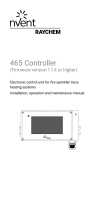
Enclosure
Exposure Temperature: –40°C to +80°C
Ingress Protection: IP 65
Entries: 2 x M25, 1 x M20, 1 x M16
Size: 120 x 160 x 90 (mm)
Weight: approx. 800 gr.
Material: polycarbonate
Lid fixing: 4 captive screws
Mounting: on a wall or directly on the pipe using
support brackets, SB-100 / SB-101 / SB-110
T sensor
Type: 3-wire Pt 100 according to IEC Class B
Sensor head: 50 mm x Ø 5 mm
Cable length: 3 m*
Cable diameter: 4 mm
Cable exposure T: –40°C to +150°C
(+215°C intermittent 1000h)
* Thesensorcablecanbeextendedwitha3-coreshieldedcableof20Ω
max. per conductor (e.g. up to 150 m with a 3x1.5 mm² cable).
The shield shall be earthed on the controller side only.
FUNCTIONAL DESCRIPTION
During normal operation, the display alternates between the measured
temperature and the set point temperature.
When the measured pipe temperature exceeds the programmed setpoint
value plus hysteresis, the switching contact opens and the heating cable
is switched off.
When the measured pipe temperature falls below the setpoint value
minus hysteresis, the switching contact closes. A LED in the display
indicates that the heating cable is switched on.
In the event of an error, the alarm relay switches and an error code shows
on the display. It is possible to program the status of the heating cable
(on or off) in case of a sensor error.
The unit is fitted with a battery so that programming can be done on
the bench prior to mounting in the working location (see Operational
description, page 11).

8 | nVent.com
DISPLAY
RAYSTAT-CONTROL-10 has a digital display. The three left hand digits 9a
are the value display and the right hand digit 9b is the status display.
There are 4 different display modes possible:
1. In the normal operation mode (no error condition), the measured
temperature or the set point temperature value are displayed in the
value display (alternating).
During the time that the actual measured temperature is shown in the
value display, the XT LED in the status display lights up.
When the set point temperature is shown, the WT LED in the status
display lights up.
Also during normal operation, the middle horizontal LED in the status
displaylightsupforthetimethattheheater(mainrelay)isON( ).
For example: means 20°C measured temperature and heater
is switched on, means set point temperature 24°C and heater
is switched on.
2. In case an error is detected, the value display shows “ ” (flashing)
and the status display indicates the error number (see Errors).
3. Programming is done by means of the push buttons (see Operational
description). In the programming mode, the status display will indicate
the code of the parameter that is selected. The value display indicates
the value for the parameter.
4. When power is initially applied, all display segments will illuminate for
a short period. This will also occur if no mains power is available and
the battery button is pressed. Do not push the battery button when the
unit is powered, as this will shorten battery life.
INSTALLATION DESCRIPTION
1. Installation of heating cable
For design and selection of heating cables in sanitary applications, follow
the Technical Handbook.
For selection of industrial heating cables, follow the Selection Guide
for Industrial Trace-Heating Systems or use the latest version of
nVentRAYCHEMTraceCalcorcontactyournVentrepresentative.
Follow the design guidelines and install the system in accordance with
the system specifications.
Follow the “Product Safety Notice” supplied with the heating cable.
Residual current device (RCD 30 mA) is required.
The RAYSTAT-CONTROL-10 is a sensitive electronic device, and should be
installed taking care of common guidelines for EMC interference.

nVent.com | 9
2. Mounting of the enclosure
The RAYSTAT-CONTROL-10 can be installed indoor or outdoor.
Do not install the thermostat under the thermal insulation.
A. Wall mounting
Mount the enclosure using wall fasteners (screws) via the four,
4 mm + holes.
B. Mounting on a pipe
nVent offers different support brackets (not included) to mount the
RAYSTAT-CONTROL-10 on a pipe: SB-100, SB-101 or SB-110.
3. Wiring
Remove the terminal protection cover to access the terminals.
Power cable:
Enter a single phase (230 Vac.) power cable through the M25
gland 2 (see drawing A ) and wire according to the wiring diagram (page
37).
Wiring the heating cable can be done either:
A. Via junction box or contactor or when using nVent RAYCHEM RayClic
with the cold cable through the M25 gland 3 .
B. Directly into RAYSTAT-CONTROL-10.
In this case, the M25 gland 3 , which is delivered pre-mounted to the
RAYSTAT-CONTROL-10, is to be replaced by an appropriate kit.
Follow instructions supplied with the kit for installation.
Important: For Voltage Free Operation, the wire links (W1) and (W2)
need to be removed. Failure to remove the wire links can result in
damage to the unit or to other connected equipment. Wiring of RAYSTAT-
CONTROL-10 to a remote alarm is optional through the M20 gland 4 . It is
strongly recommended to use a remote alarm for critical operations (e.g.
when extreme low temperatures (lower than –25°C) can be expected or
for critical processes).

10 | nVent.com
4. Installation of the sensor
90°
A
B
C
D
20 mm
Location
– as indicated in the system design documentation
– not on valves, flanges, supports, pumps or other heat sinks
– at the top of the pipe for thermally sensitive pipe contents (A)
– on lower quadrant of pipe 90° for single heating cable (B)
– on lower quadrant of pipe centrally between the heating cables if
they are two or more (C)
Attachment of the sensor
– fix sensor firmly on surface with adequate fixing tape (same tape as
used to fix heater to the pipe) in two places (D)
– fix sensor parallel to pipe (D)
– route sensor cable and eventual extension cable to avoid damage in
use. Fix to pipe with adequate tape where appropriate.
Warning: Do not install sensor at ambient temperatures below –20°C. Do
not bend sensor (last 50 mm), keep it straight under all circumstances.
Min. bending radius for sensor cable: 10 mm.
Wiring sensor to RAYSTAT-CONTROL-10
Enter the sensor cable through the indicated M16 gland 5 and wire as
shown in the wiring diagram (page 37). Please pay attention to color
coding of the wiring.

nVent.com | 11
Remark: The sensor cable can be extended up to 150 m when a cross
sectionof3x1,5mm²isused(max.20Ωperconductor).Theconnection
between sensor cable and sensor extension can be made in junction
box JB-86 or equivalent. Use a shielded cable for extension to avoid
interference. The shielding braid is to be earthed in the thermostat.
5. Complete installation
A
A
A
Put the terminal protection cover back in place.
If RAYSTAT-CONTROL-10 is not yet programmed, please do so as
described in Operational description (page 11) and onwards.
Close the lid of the unit.
Ensure that the pipe and sensor are thermally insulated and clad to the
design specification after installation of thermostat.
Seal cladding with sealant (A).

12 | nVent.com
OPERATIONAL DESCRIPTION
1. Introduction
The nVent RAYCHEM RAYSTAT-CONTROL-10 parameters are configured
via a menu system.
The unit is delivered with a battery so that the operating parameters can
be set up without any need for the power supply to be connected. This
is useful for setting units on the bench prior to mounting in their working
location or on site when power isn’t available.
Please note that the Battery key ( ) must not be pressed whilst
the unit has the power supply connected. It will cause the battery to
discharge immediately. The battery will be disconnected automatically
when the last para-meter has been set.
Once programmed, the settings will be retained even in case of power
loss.
2. Activating and navigating the Menu in Set-Up mode
In order to activate the Set-up mode when the unit is not connected to a
mains power supply, press the Battery key ( ) for about 2 sec.
This action will immediately light up all segments of the display, so
correct functioning of the display can be verified. The display will then
shortly show , and switch to the first parameter to be changed.
In order to activate the Set-up mode when the unit is connected to a
mains power supply (the display alternates between the setpoint and
actual measured temperature), press the MENU key for about 2 sec. The
display will shortly show , and switch to the first parameter to be
changed.
Stepping through the complete parameter list can be done by
successively pressing the MENU key. When the last parameter has
been set, the display will show , and return to normal operation.
In case the unit is not connected to a power supply, the battery will be
disconnected.
If the unit is in Set-up mode, but no keys are activated, it will return to the
normal operation (or switch the battery off when the battery is used) after
about 30 sec.

nVent.com | 13
To alter any parameter shown in the display, press the + or – keys. This
will allow the parameter to be raised or lowered to the maximum or the
minimum in integer steps.
If you require to reset all parameters to their default value, press the +
and – keys together for about 2 sec. If this is succesful, the display will
show .
3. Parameters
The first parameter to show up during Set-up mode is the Set Point. Other
parameters, their default, minimum and maximum values are shown in
the below table:
Parameter Default
Value
Displayed
Code
Min. Max.
Set Point (°C)
3
0 150
Hysteresis (K)
1
1 5
Low Temperature
Alarm Threshold
1
(°C)
0 –40 148
1
High Temperature
Threshold (°C)
65 2
2
150
3
Heater Operation if
Sensor Error
1 0 (OFF) 1 (ON)
Voltage Free
Operation
0
0 (NO) 1 (YES)
1
Max. Low Temp. Alarm is always smaller than Set Point minus
hysteresis.
2
Min. High Temp. Alarm is always larger than Set Point plus hysteresis.
3
Consider also max. exp. temp. of heating cable in table,to select an
appropriate High Temp. Alarm value. If one does not want the High
Temp. Alarm to be active, set the value to , which comes after
150.

14 | nVent.com
4. Errors
Error Code Description Remedy
Short Circuit
Sensor (or very low
resistance)
1. De-energize/isolate unit from power supply
2. Disconnect sensor and verify sensor resistance Rs between white wire and each of
the red wires > 80 Ohm
3. If Rs < 80 Ohm, replace sensor (HARD-78)
4. Otherwise verify sensor wiring and/or sensor extension lead and reconnect
Open Circuit Sensor 1. De-energize/isolate unit from power supply
2. Disconnect sensor and verify sensor resistance Rs between white wire and each of
the red wires < 166 Ohm
3. If Rs > 166 Ohm, replace sensor (HARD-78)
4. Otherwise verify sensor wiring and/or sensor extension lead and reconnect
Low Temperature
Threshold Alarm
1. Verify heating system & sensor position
2. Verify appropriateness of Low Temperature Alarm setting in Menu
High Temperature
1
Threshold Alarm
1. Verify heating system and sensor position
2. Verify appropriateness of High Temperature Alarm setting in Menu
Output Voltage
Error
2
1. De-energize/isolate unit from power supply
2. If no contactor:
a. Verify that Wire bridge W1 interconnects Terminal 3 and 6 (L)
b. Verify that Wire bridge W2 interconnects Terminal 5 and 8
3. In case a contactor is connected, set parameter U to 1 (Voltage Free) in Menu
4. Verify that the sensor extension is shielded and grounded
5. If Err 5 re-occurs and remains, the output relay or triac is defect: replace unit
Supply below
207Vac.
3
Verify supply voltage between terminals 7 (L) and 10 (N) when Error 6 is displayed
1
Detection of this error is disabled if
High Temperature Alarm is set off.
2
Detection of this error is disabled in
Voltage Free Mode.
3
Unit is not active when supply voltage
is below approx. 190 Vac.
All alarms are on the same alarm relay.
An alarm will clear automatically as soon as the error condition is gone. There is no
need to reset; all settings are maintained.
If multiple alarms are active, the alarms are shown with the following priority:
(Highest),
, , , , (Lowest)

nVent.com | 15
TESTING, COMMISSIONING AND
MAINTENANCE
Test heating cable when thermostat installation is complete as directed
in the nVent instructions applicable for the heating cable. Fill out the
commisioning sheet (page 39).
Maintain thermostat during normal plant maintenance.
Check: Mounting is firm
Exposed sensor cable is not damaged
Glands are tightened firmly
Thermostat operation is correct (no error code displayed)
Thermostat settings suits application
Lid is closed firmly.
Cladding is sealed with sealant.
Disposal of Waste batteries
(Applicable regulations for the European Union)
The crossed out dustbin on the product and/or packaging indicates that
the battery contained in the product shall not be disposable as part of
normal household waste.
The batteries must be disposed of responsibly to avoid potentially
negative consequences to the environment and/or human health.
The recycling of the materials can also help conserve natural resources.
For more information on battery disposal, please contact your local civic
office or your domestic waste disposal service.

16 | nVent.com
BESCHREIBUNG
Der elektronische Thermostat nVent RAYCHEM RAYSTAT-CONTROL-10
ist mit einem digitalen Display und umfassenden Alarmfunktionen
ausgestattet. Er wurde speziell für elektrische Beheizungen entwickelt
und ist für das Schalten von großen Stromen ausgelegt (25 A).
Die Heizleitung wird entweder direkt über den Thermostat oder über
einen Leistungsschütz ein- und ausgeschaltet. Bei einem Schaltstrom
von weniger als 25 A ist eine Schaltung über den Thermostaten RAYSTAT-
CONTROL-10 zu empfehlen. Für einen Schaltstrom von mehr als 25 A
enthält der RAYSTAT-CONTROL-10 einen potentialfreien Kontakt zur
Ansteuerung eines Leistungsschützes.
Die Installation und der Anschluss der Steuerung müssen entsprechend
den örtlich geltenden Bestimmungen erfolgen. Der Thermostat RAYSTAT-
CONTROL-10 darf nicht in explosionsgefährdeten Bereichen installiert
werden. Für explosionsgefährdete Bereiche bietet nVent spezielle
Thermostate an.
Technische Daten
Betriebsspannung: AC 230 V, +10%/–10%, 50/60 Hz
(inkl. einem auslaufgeschützten,
wartungsfreien, nichtwiederaufladbaren 6
V-Akku)
Nennstrom: max. 25 A bei AC 230 V, ohmsche Last
Heizleitung bei
Sensorfehler: Programmierbar: EIN oder AUS
Hysterese: Programmierbar: 1 bis 5 K
Temperaturbereich: 0°C bis +150°C
Schaltgenauigkeit: ±0,5 K bei 5°C
Umgebungstemperatur-
bereich: –40°C (–25°C, VDE zertifiziert) bis +40°C
Benutzerschnittstelle: Digitales Display
4 Tasten zur Programmierung
Alarmrelais, Wechlsler potentialfrei,
max. 2 A, AC 230 V
Stromanschluss: 3 Anschlussklemmen für 0,75 bis 4 mm²
Alarmrelais-Anschluss: 3 Anschlussklemmen (+ ) für 0,75 mm²
bis 2,5 mm²
Sensorkabel-Anschluss: 3 Anschlussklemmen (+ ) für 0,75 mm²
bis 2,5 mm²
Steuerrelais-Anschluss: 2 Anschlussklemmen (+ ) für 0,75 mm²
bis 4 mm²

nVent.com | 17
Gehäuse
Umgebungstemperatur-
bereich: –40°C bis +80°C
Schutzart: IP65
Bohrungen: 2 x M25, 1 x M20, 1 x M16
Abmessungen: 120 x 160 x 90 (mm)
Gewicht: ca. 800 g
Material: Graues Polycarbonat
Deckelbefestigung: 4 x M6, Zylinderkpfschrauben - rostfreier
Stahl, unverlierbar
Montage: Wandmontage oder auf
Befestigungswinkel SB-100, SB-101, SB-110
Temperatursensor
Typ: in 3-leitertechnik Pt 100 (IEC Class B)
Sensorkopf: 50 mm x ⊕ 5 mm
Kabellänge: 3 m*
Kabeldurchmesser: 4 mm
Umgebungstemperatur-
bereich: –40°C bis +150°C (kurzzeitig +215°C)
* Das Sensorkabel kann mit einem 3-adrigen abgeschirmten Kabel,
max.20ΩjeLeiter,verlängertwerden(biszu150mbeieinem
Leiterquerschnitt von 3 x 1,5 mm²).
Die Erdung ist nur am Thermosteten vorzunehmen.
FUNKTIONSBESCHREIBUNG
Bei Normalbetrieb erscheinen im Display abwechselnd die Werte
für die gemessene Umgebungstemperatur und die eingegebene
Haltetemperatur. Wenn die gemessene Rohrtemperatur die
programmierte Haltetemperatur plus Hysterese übersteigt, öffnet der
Schaltkontakt, und die Heizleitung wird ausgeschaltet.
Wenn die gemessene Rohrtemperatur unter die programmierte
Haltetemperatur minus Hysterese fällt, schließt der Schaltkontakt. Eine
LED in der Statusanzeige zeigt an, dass die Heizleitung eingeschaltet ist.
Bei einer Störung schaltet das Alarmrelais und in der Anzeige
erscheint eine Fehlermeldung. Sie können außerdem eingeben, ob
das Heizsystem bei einem Sensorausfall abschalten oder weiter in
TCRUC-BE.БЛ08.B.01634

18 | nVent.com
Betrieb bleiben soll (EIN oder AUS). Der Thermostat ist zusätzlich mit
einer Batterie ausgestattet, so dass die Programmierung auch ohne
Spannungsversorgung direkt vor Ort vorgenommen werden kann (siehe
„Programmierung“ auf Seite 21).
DISPLAY
Das Thermostat RAYSTAT-CONTROL-10 ist mit einem digitalen Display
ausgestattet. Das dreistellige Display links 9a gibt die Messwerte
an, das Display rechts 9b den Status. Das Display gibt an, in welchen
Betriebszustand sich die Beheizung befindet:
1. Bei normalem Betrieb werden die aktuelle Rohrtemperatur oder der
Sollwert für die Haltetemperatur im linken Display abwechselnd
angezeigt.
Solange die aktuelle Rohrtemperatur angezeigt wird, leuchtet die
LED XT in der Statusanzeige rechts. Wenn die Haltetemperatur
(Sollwert) im linken Display angezeigt wird, leuchtet die LED WT in der
Statusanzeige. Im Normalbetrieb leuchtet auch die LED in der Mitte.
Sie zeigt an, dass die Heizleitung (Hauptrelais) eingeschaltet
ist ( ).
Beispiel: bedeutet, es werden aktuell 20°C gemessen, und die
Heizleitung ist eingeschaltet. bedeutet, die Haltetemperatur
beträgt 24°C, und die Heizleitung ist eingeschaltet.
2. Im Falle einer Störung blinkt im linken Display die Meldung „
“, und in der Statusanzeige erscheint ein Fehlercode (siehe
„Fehlermeldungen“).
3. Die Programmierung erfolgt mit Hilfe der Bedientasten (siehe
„Funktionsbeschreibung“). Während der Programmierung erscheint
in der Statusanzeige der Code für den Parameter, der gerade
programmiert wird. Im linken Display wird gleichzeitig der jeweilige
Wert angezeigt.
4. Wird die Spannungsversorgung eingeschaltet, so leuchten alle
Segmente im Display kurzzeitig auf. Dies geschieht auch, wenn
keine Spannungsversorgung angeschlossen ist und die Batterie-
Taste gedrückt wird. Drücken Sie die Batterie-Taste niemals, wenn
eine Spannungsversorgung angeschlossen ist, da sich sonst die
Lebensdauer der Batterie verkürzt.
MONTAGE
1. Montage der Heizleitung
Informationen zur Auswahl und Auslegung von Frostschutzsystemen in der
Bautechnik finden Sie in unserem Technischen Handbuch.
Eine detaillierte Auswahlhilfe für industrielle Beheizungssysteme von nVent
finden Sie in unserer Projektierungsanleitung, bzw. in unserer speziell

nVent.com | 19
entwickelten Planungssoftware „nVent RAYCHEM TraceCalc“. Für Fragen
zu individuellen Anwendungen wenden Sie sich bitte direkt an Ihre nVent-
Vertretung.
Um die ordnungsgemäße Funktion des Systems sicherzustellen, müssen
die Auslegungsvorschriften und die Montageanleitung exakt befolgt
werden. Beachten Sie bitte auch das mitgelieferte Sicherheitsdatenblatt.
Hinweis:Es ist ein Fehlerstromschutzschalter (30mA) erforderlich.
Der RAYSTAT-CONTROL-10 ist ein empfindliches elektronisches Gerät
und sollte unter Berücksichtigung der allgemeinen Richtlinien zur
elektromagnetischen Verträglichkeit (EMV) installiert werden.
Der Thermostat RAYSTAT-CONTROL-10 ist für max. 25 A ausgelegt, die
max. Heizkreislänge ist somit begrenzt. Größere Heizkreislängen können
durch einen potentialfreien Kontakt über ein Leistungsschütz geschaltet
werden (es sind nur entstörte Schütze zu verwenden).
2. Gehäusemontage
Der Thermostat RAYSTAT-CONTROL-10 kann im Freien oder innerhalb
von Gebäuden montiert werden. Montieren Sie das Gerät nicht unter der
Wärmedämmung!
A. Wandmontage
Für die Wandmontage sind vier Löcher für M4-Schrauben im Gehäuse.
B. Montage auf der Rohrleitung
nVent bietet auch Befestigungswinkel (nicht im Lieferumfang
enthalten) für die Montage auf der Rohrleitung an: SB-100 / SB-101 /
SB-110.
3. Anschluss
Entfernen Sie zuerst die Gehäuseabdeckung.
Anschlusskabel
Führen Sie ein einphasiges Anschlusskabel (AC 230 V) durch die dafür
vorgesehene M25-Verschraubung 2 (sieheZeichnungA )undschließen
Sie das Kabel entsprechend dem Anschlussdiagramm auf Seite 37 an.
Heizleitungsanschluss
A. Die Heizleitung kann über einen Anschlusskasten, ein Leistungsschütz
oder mit dem Kaltende des Anschlussmoduls nVent RAYCHEM RayClic
direkt durch die M25-Verschraubung 3 angeschlossenwerden.
B. Die Heizleitung kann auch direkt im Thermostat angeschlossen
werden. In diesem Fall muss die M25-Verschraubung 3 ,diebei
der Lieferung bereits an dem Thermostat montiert ist, durch eine
entsprechende Anschlussgarnitur ersetzt werden. Montieren Sie die
Anschlussgarnitur entsprechend der mitgelieferten Montageanleitung.

20 | nVent.com
Hinweis: Für potentialfreien Betrieb müssen die Verbindungskabel
(W1 und W2) entfernt werden, da sonst der Thermostat oder andere,
daran angeschlossene Komponenten beschädigt werden können. Bei
kritischenProzessenoderextremniedrigenUmgebungstemperaturen
(unter -25°C) wird die Verwendung einer externen Alarmeinheit
empfohlen. Diese kann über die M20-Verschraubung 4 direkt am
Thermostaten angeschlossen werden.
4. Sensormontage
Montageort des Sensors
90°
A
B
C
D
20 mm
– wie in der Projekt-Auslegung vorgesehen
– nicht in der Nähe von Ventilen, Flanschen, Rohrlagern, Pumpen
oder anderen wärmeabstrahlenden Komponenten, wenn diese
ordnungsgemäss beheizt werden
– bei temperaturempfindlichen Medien: oben auf der Rohrleitung (A)
– bei einzelnen Heizleitungen: im unteren Quadranten der Rohrleitung,
im 90°-Abstand zur Heizleitung (B)
– bei zwei oder mehreren Heizleitungen: im unteren Quadranten der
Rohrleitung in der Mitte zwischen den beiden Heizleitungen (C)
Befestigung des Sensors
– Befestigen Sie den Sensor an zwei Stellen mit Klebeband auf der
Rohrleitung (D)
– Befestigen Sie den Sensor parallel zur Rohrleitung (D)
– Verlegen Sie die Sensorleitung so, dass sie keiner mechanischen
Beschädigung ausgesetzt ist. Befestigen Sie das Kabel mit
Klebestreifen an der Rohrleitung.
/