Page is loading ...

Wiring Information
Rev. 1/28/00
SEC-8028
Yellow ~ Main Battery Connection (+) Fuse ~ 5 Amp MAX
Connect to a constant 12-volt source. Alpine recommends this wire to be
connected directly to the battery. Do not share this power lead with any
other components or accessories. Use a 5-amp fuse in-line at the battery
lead to protect against short circuit.
Red ~ Ignition (+)
Connect to a 12-volt ignition source. When selecting the N/O starter
interrupt, it is necessary to find a “true” ignition source for the Red wire.
When selecting the N/C starter interrupt, you may use an accessory lead.
Black ~ Chassis Ground (–)
Connect directly to a metal surface that has been cleaned from any paint or
coating. This wire should be as short as possible and should not be
connected directly to the battery.
Blue ~ Siren (+) 1.5 Amp
Connect to the Blue wire of the siren. Connect the Black wire of the siren to
chassis ground. If more than one siren will be used, use a relay to drive
all of the sirens.
Orange ~ Starter Interrupt Output (+) 200mA
Connect the Orange wire of the security system to the Orange wire of the
supplied relay. Connect the Black wire of the starter interrupt relay to
chassis ground. The starter interrupt can be configured as a normally open
(N/O) or normally closed (N/C) circuit.
NORMALLY CLOSED STARTER INTERRUPT
–Normally Closed is
the factory default setting. This configuration will assure that the vehicle
will always start as long as the security system is disarmed, even in the
event of a security system malfunction or component failure.
NORMALLY OPEN STARTER INTERRUPT
–This configuration adds
more security for the customer by not allowing the vehicle to start even if a
would-be thief finds and removes the main unit or main power connection.
Open the Main Unit. Locate the jumper labeled JP1. This is the only jumper
selection inside of the main unit. Jumper JP1 will select either normally
open or normally closed starter kill relay operation. The factory default is
normally closed, or in the “OFF” position. To select normally open starter
disable, place jumper JP1 to the “ON” position. When using this feature, it
is important that the Red (ignition) wire be connected to a “true” ignition
source-12 volts through the “On” and “Start” cycles. This feature must be
enabled. See the Jumper Selection section for more details.
Yellow/Red ~ Extension LED Output (+) 20mA
Connect to the Yellow/Red of the extension LED. Connect the Black wire of
the extension LED to chassis ground. Up to 4 additional LEDs can be added
in series with the original LED. Do Not Parallel LEDs. The correct mounting
hole size is 15/64".
Red/White ~ Valet/Disarm Switch Input (–)
Connect the Red/White wire to the Red/White wire of the Valet/Disarm
switch. Connect the Black wire of the Valet/Disarm switch to chassis ground.
Brown/White ~ Door Switch Input (+ or –)
Determine the vehicle’s door pin polarity. Refer to the Programming section
if positive door input is required. Connect the Brown/White wire to the
vehicle’s door pin wire.
Green/White ~ Hood /Trunk Wire (–)
Connect the Green/White wire to the vehicle’s hood pin and/or trunk pin
wire. If both hood and trunk pin are connected to this input, you must diode
isolate each wire.
Yellow/Green ~ EXT-1 Output {(–) 1-Second or Latched} 200mA
Connect the Yellow/Green wire to control an optional accessory when the
EXT-1/Valet button is pressed and released. Some examples might include
devices such as a remote starter or window roll-up modules. Refer to the
accessory’s owner’s manual for installation instructions.
Yellow/Black ~ EXT-2 Output {(–) 1-Second or Latched} 200mA
Connect the Yellow/Black wire to control an optional accessory when the
EXT-2/EXT-3 button is pressed and released. Some examples might include
devices such as window roll-up modules or a trunk actuator. Refer to the
accessory’s owner’s manual for installation instructions.
Yellow/Brown ~ EXT-3 Output {(–) Continuous or 1-Second} 200mA
Connect the Yellow/Brown wire to control an optional accessory when the
EXT-2/EXT-3 button is pressed and held for more than 2 seconds. Some
examples might include devices such as a trunk actuator or a garage door
opener. Refer to the accessory’s owner’s manual for installation instructions.
Blue/White ~ Arming Output (–) 200mA
Connect the Blue/White wire to control an optional accessory that will be
controlled when the security system is armed. Some examples might
include devices such as window roll-up modules or additional optional
sensors. Refer to the accessory’s owner’s manual for installation instructions.
Blue/Green ~ Digital Pager Data Output
The Blue/Green wire is only for use with the optional SEC-8205 Multi-
Channel Digital Paging System. Connect the Blue/Green wire to the
Blue/Green wire of the optional SEC-8205 Multi-Channel Digital Paging
System. Do not use this wire with a conventional vehicle paging system.
Blue/Yellow ~ Dome Light Surv. Output (+ or –) 10 Amp MAX
NEGATIVE TYPE-
Connect the Blue/Yellow wire to pin 85 of a
standard Bosch type automotive relay. Connect a fused 12-volt source to
pin 86. Connect chassis ground to pin 87. Finally, connect the vehicle’s
dome light wire to pin 30 of the relay.
POSITIVE TYPE-
Connect the Blue/Yellow wire to pin 85 on a stan-
dard Bosch type automotive relay. Connect a fused 12-volt source to pin 86 and
pin 87. Finally, connect the vehicle’s dome light wire to pin 30 of the relay.
Yellow/White & White ~ Parking Light Flash Input (+ or –) 10 Amp MAX
Determine the correct polarity of the parking light circuit for the vehicle.
Connect the Yellow/White wire to a constant 12V+ source or to chassis
ground, depending upon the vehicle. Connect the White wire to the vehicle’s
parking light wire.
Black/White ~ Ignition/Impact Disable Input (–)
Connect the Black/White wire to the optional remote starter module’s nega-
tive output while engaged. (AKA-the sensor inhibit or sensor interrupt wire)
On-Board Door Lock/Unlock Relays (15 Amp MAX)
The SEC-8028 includes two on-board relays for locking and unlocking the
door lock system, without the need for external relays. The relays are switched
internally when the security system is either armed or disarmed. For wiring
diagrams, call Alpine FastFax and order document number 20030.
White/Blue ~ Priority Unlock Output (–) 200mA
If the Priority Unlock feature is selected, the SEC-8028 door unlock wires
(White/Green and Green/Blue) should be connected directly to the driver’s
door unlock motor wires as reverse polarity. This will unlock the driver’s door
upon disarm. The White/Blue wire should then be connected to the door
unlock wire for the type of door lock system that the vehicle requires. The
remaining doors will unlock when the TX button is pressed a second time
within five seconds after disarm. Some vehicles with factory keyless entry
may have the necessary wiring available at the keyless entry module. This
feature must be enabled. See the Feature Programming section for more de-
tails. Additional relays may be required for this feature. For wiring diagrams,
call Alpine FastFax and order document number 20040. Use only the un-
lock portion of these diagrams for the White/Blue wire.
Page 1
Installation Instructions (English)

Feature Programming
Rev. 1/28/00
SEC-8028
Page 2
Installation Instructions (English)
Disarmed &
not in VALET Mode
Function Setup
Sensor Setup
EXT Setup
Turn Ignition On
LED will Blink for One Second then
TX/
PANIC
EXT2/
EXT3
EXT1/
VALET
MODE
1
Siren will Chirp Once
Press MODE
Press MODE
Press TX/PANIC
Hold the Disarm/Valet Switch for 1 Second then
Press MODE on the Remote Control within 1 Second
T
X
/
P
A
N
I
C
E
XT2/
EX
T3
EX
T
1/
V
ALE
T
M
OD
E
T
X
/
P
A
N
I
C
E
X
T
2
/
E
X
T
3
E
X
T
1
/
V
A
L
E
T
M
O
D
E
T
X
/
P
A
N
I
C
E
X
T
2
/
E
X
T
3
E
X
T
1
/
V
A
L
E
T
M
O
D
E
Press MODE
1 Chirp 2 Chirp
ON
Turn Ignition OFF at
anytime to exit Programming
Mode
OFF
From top of the row
Chirp Select
1-short LED blink
(repeating)
Siren will "Chirp" Once Siren will "Chirp" Twice Siren will "Chirp" Three times
ON OFF
Press
TX/PANIC
Press TX/PANIC
Press EXT-1 Press EXT-2
Press MODE
Auto Lock
2-short LED blinks
(repeating)
OFF ON
Press
TX/PANIC
Press TX/PANIC
Press EXT-1 Press EXT-2
Press MODE
Ignition Lock
3-short LED blinks
(repeating)
OFF ON
Press
TX/PANIC
Press TX/PANIC
Press EXT-1 Press EXT-2
Press MODE
Ignition Unlock
4-short LED blinks
(repeating)
OFF ON
Press
TX/PANIC
Press TX/PANIC
Press EXT-1 Press EXT-2
Press MODE
Arming Type
1-long LED blink
(repeating)
Manual Auto
Press
TX/PANIC
Press TX/PANIC
Press EXT-1 Press EXT-2
Press MODE
Siren Duration
1-long, 1-short LED blinks
(repeating)
30 Sec. 60 Sec.
Press
TX/PANIC
Press TX/PANIC
Press EXT-1 Press EXT-2
Press MODE
Door Lock Pulse Length
1-long, 2-short LED blinks
(repeating)
1 Sec. 3 Sec.
Press
TX/PANIC
Press TX/PANIC
Press EXT-1 Press EXT-2
Press MODE
Panic Arm
1-long, 3-short LED blinks
(repeating)
OFF ON
Press
TX/PANIC
Press TX/PANIC
Press EXT-1 Press EXT-2
Press MODE
2-Car Operation
1-long, 4-short LED blinks
(repeating)
Car 1 Car 2
Press
TX/PANIC
Press TX/PANIC
Press EXT-1 Press EXT-2
Press MODE
Double Pulse Door Unlock
2-long LED blinks
(repeating)
OFF ON
Press
TX/PANIC
Press TX/PANIC
Press EXT-1 Press EXT-2
Press MODE
Priority Door Unlock
2-long, 1-short LED blinks
(repeating)
OFF ON
Press
TX/PANIC
Press TX/PANIC
Press EXT-1 Press EXT-2
Press MODE
Press EXT-2 to go to
the bottom of the row
TX/
PANIC
EXT2/
EXT3
EXT1/
VALET
MODE
Press TX/PANIC
1 Chirp 2 Chirp
From top of the row
Door Sensor Input
1-short LED blink
(repeating)
ON OFF
Press
TX/PANIC
Press TX/PANIC
Press EXT-1 Press EXT-2
Press MODE
Door Sensor Polarity
2-short LED blinks
(repeating)
Negative Positive
Press
TX/PANIC
Press TX/PANIC
Press EXT-1 Press EXT-2
Press MODE
Hood/Trunk Sensor Input
3-short LED blinks
(repeating)
ON OFF
Press
TX/PANIC
Press TX/PANIC
Press EXT-1 Press EXT-2
Press MODE
Impact Sensor Input
4-short LED blinks
(repeating)
ON OFF
Press
TX/PANIC
Press TX/PANIC
Press EXT-1
Press EXT-2
Press MODE
Press EXT-2 to go to
the bottom of the row
T
X
/
P
A
N
I
C
E
X
T
2
/
E
X
T
3
E
X
T
1
/
V
A
L
E
T
M
O
D
E
TX/
PANIC
EXT2/
EXT3
EXT1/
VALET
MODE
Press TX/PANIC
1 Chirp 2 Chirp
From top of the row
EXT-1 Output Configuration
EXT-2 Output Configuration
EXT-3 Output Configuration
1-short LED blink
(repeating)
1 Sec.
Latched
Press
TX/PANIC
Press TX/PANIC
Press EXT-1 Press EXT-2
Press MODE
2-short LED blinks
(repeating)
1 Sec.
Latched
Press
TX/PANIC
Press TX/PANIC
Press EXT-1 Press EXT-2
Press MODE
3-short LED blinks
(repeating)
Continuous
1 Sec.
Press
TX/PANIC
Press TX/PANIC
Press EXT-1 Press EXT-2
Press MODE
EXT Trunk & Impact
Sensor Cancel
1-long LED blink (repeat)
ON OFF
Press
TX/PANIC
Press TX/PANIC
Press EXT-1 Press EXT-2
Press MODE
EXT Trunk & Impact
Sensor Selection
1-long, 1-short LED blinks (rpt)
EXT-2 EXT-3
Press
TX/PANIC
Press TX/PANIC
Press EXT-1 Press EXT-2
Press MODE
EXT-1 Impact & Ignition
Sensor Disable
4-short LED blinks (repeat)
OFF ON
Press
TX/PANIC
Press TX/PANIC
Press EXT-1
Press EXT-2
Press MODE
Press EXT-2 to go to
the bottom of the row
TX/
PANIC
EXT2/
EXT3
EXT1/
VALET
MODE
SEC-8428 Remote Control Layout
TX/PANIC
MODE
EXT1/VALET
STATUS LED
EXT1/VALET
Press and
release to
activate EXT-2.
Press and Hold to
activate EXT-3.
Blinks once while transmitting
CAR 1 information and will
Blink TWICE while
transmitting CAR 2
Information.
Press and release
to activate the
MODE function for
programming
options.
Press and release
to activate the
ARM/DISARM
Command. Press
and Hold for 3-
Seconds to
Activate the Panic
Command.
Press and release
to activate the
EXT-1 Command.
Press and Hold for
3-Seconds to
Activate the
PROTECTED
VALET mode.
NOTE 1: Pressing and Holding both TX/PANIC and EXT1/VALET for more
than 2-seconds will change the car transmit status (CAR-1/CAR-2).
NOTE 2: See Owners Manual for complete operation and additional functions.

Impact Sensor Adjustment
Remote Control Programming
1. The system must be disarmed. Press and hold the Valet/Disarm switch in
the ON position during the entire coding procedure.
2. While holding the Valet/Disarm switch in the ON position, switch
ignition on and off three times. The LED will blink rapidly.
3. Press the TX/PANIC button on the remote control that you wish to program.
The siren will chirp twice to verify receiving the new remote control code.
4. Release the Valet/Disarm switch.
NOTE - The SEC-8028 can learn up to four remote control identification codes. When a new remote is coded, the security system will “bump-out” the oldest
code if the system originally contained four remote control identification codes.
TX/
PANIC
EXT2/
EXT3
EXT1/
VALET
MODE
Rev. 1/28/00
SEC-8028
T
X
/
P
A
N
IC
E
X
T
2/
E
X
T
3
E
X
T
1
/
V
A
L
E
T
M
O
D
E
TX/
PANIC
EXT2/
EXT3
EXT1/
VALET
MODE
TX/
PANIC
EXT2/
EXT3
EXT1/
VALET
MODE
Within five seconds, press and imediatly release (DO NOT HOLD) the TX/Panic and
EXT-1/Valet buttons simultaneously. The status LED will illuminate once again. The system is
now in the Impact Sensor Sensitivity Adjustment mode for the pre-warn field.
Press and release the TX/Panic button to increase the pre-warn sensitivity. Press and release the
EXT-1/Valet button to decrease the pre-warn sensitivity. Each time the sensitivity is adjusted, the
siren will chirp once. When the maximum or minimum sensitivity is reached, the siren will chirp
twice. To test the pre-warn sensitivity level, strike the vehicle with a light impact. The status LED
will blink once to indicate that the pre-warn sensitivity level has been exceeded.
The system must be disarmed. Place the system into the Valet mode through the Valet/Disarm
switch. The status LED will illuminate for one second.
When the pre-warn sensitivity level is acceptable, press and release the TX/Panic and
EXT-1/Valet buttons simultaneously to adjust the final trigger sensitivity level. The siren will
“chirp” three (3) times to indicate that you are in the final trigger sensitivity adjustment mode.
When the sensitivity adjustment procedure is completed, press and release the TX/Panic and
the EXT-1/Valet buttons simultaneously. The status LED will blink twice and you will exit the
adjustment mode. The system has now returned to the disarmed state.
Press and release the TX/Panic button to increase the final-trigger sensitivity. Press and release the
EXT-1/Valet button to decrease the final-trigger sensitivity. Each time the sensitivity is adjusted, the
siren will chirp once. When the maximum or minimum sensitivity is reached, the siren will chirp
twice. To test the sensitivity level, strike the vehicle with enough impact in which you feel should
trigger the system into an alarming state. The LED will blink three times indicating that the final-
trigger sensitivity level is exceeded.
Press Valet for 1 second
LED will blink once
Siren “chirps” three times
Press TX and EXT1 to
enter prewarn adjust
Press TX
to increase
sensitivity
siren chirps
once
Press EXT1
to decrease
sensitivity
siren chirps
once
Press TX and EXT1 to
enter final trigger
adjustment
Siren chirps twice
at min or max
Press TX
to increase
sensitivity
siren chirps
once
Press EXT1
to decrease
sensitivity
siren chirps
once
Siren chirps twice
at minimum or
maximum settings
LED will ablink twice
Press TX and EXT1 to
exit adjustment mode
Press and hold Valet
Press TX button on new
remote
Siren chirps twice
Turn Ignition ON/OFF 3
times
LED blinks rapidly
Release valet
T
X
/
P
A
N
I
C
E
X
T
2
/
E
X
T
3
E
X
T
1
/
V
A
L
E
T
M
O
D
E
LED will blink once
TX/
PANIC
EXT2/
EXT3
EXT1/
VALET
MODE
TX/
PANIC
EXT2/
EXT3
EXT1/
VALET
MODE
T
X
/
P
A
N
I
C
E
X
T
2
/
E
X
T
3
E
X
T
1
/
V
A
L
E
T
M
O
D
E
Page 3
Installation Instructions (English)
2
1
1
1 2
3
4
ENTER VALET MODE
ENTER PROGRAMMING MODE
ADJUST PRE-WARN SETTING
ADVANCE TO FINAL-TRIGGER SETTING
ADJUST FINAL TRIGGER SETTING
EXIT PROGRAMMING

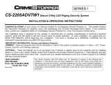
Main
Vehicle
Battery
Yellow ~ Battery
White /Brown ~ Door Lock Common (30)
Brown/Blue ~ Door Lock N/C (87A)
Brown/Red ~ Door Lock N/O (87)
Green/Red ~ Door Unlock N/O (87)
White/Green ~ Door Unlock Common (30)
Green/Blue ~ Door Unlock N/C (87A)
Normally Open (N/O)
Normally Closed (N/C)
Common
White ~ Parking Light Flash N/O (87)
Yellow/White ~ Parking Lt. Comm (30)
5 Amp Fuse (MAX)
10 Amp Fuse
20 Amp Fuse
Black - Ground
Red ~ Ignition (N/O Starter Must be True Ignition)
Black/White ~ Alarm Disable Input (-)
Yellow/Red ~ LED ( +)
Red/White ~ Valet Input (—)
Brown/White ~ Door Input (+ or —)
Blue/Green ~ Digital Pager Output
Blue/Yellow ~Dome Light Surveillance (—) 200mA
Yellow/Black ~ EXT-2 (—) 200mA
(1-Second or Latched Output)
Yellow/Brown ~ EXT-3 (—) 200mA
(Continuous or 1-Second Output)
Blue ~ Siren (+) 1.5 Amps Max
Orange ~ Starter Cut Relay
(+) 200mA
Blue/White ~ Armed Output (—) 200mA
Optional (5 LED’s Max)
Optional
To Key (30)
Use for
Normally Open
(87)
Use for
Normally Closed
(87A)
Red / Yellow
Red / White
Red
Optional
Relay
Optional
30
87
87a
Input wires for
the internal
Door Lock
Relay
Input wires for
the internal
Door Unlock
Relay
Input wires for
the internal
light flash relay
Standard Relay
For Reference
The coil contacts (85 & 86) are not needed
they are controlled within the main unit
13B
A
C
E
D
H
G
5
White/Blue ~ Optional Priority Door Unlock (-) 200mA
10
8
4
1
11
12
3
6
Yellow/Green ~ EXT-1 (—) 200mA
(1-Second or Latched Output)
15
16
18
7
F
Disarm/Valet
Switch
Part No.
01V91400F82
Siren
Part No.
50T55282W01
Starter Cut Relay
Part No.~ 80T25274W01
Green/White ~ Hood/Trunk Input (—)
2
14
Electronic Impact Sensor (Included)
5A
20A
10A
To SEC-8205
Digital Pager
(Optional)
1
10
12
14
18
4
3
8
9
7
11
13
15
17
2
6
5
16
A
G
C
B HFD
E
HGFEDCBA
ELECTRONIC
IMPACT SENSOR
Connect grounding output
from optional remote
start module to disable
ignition and impact trigger.
JP1
OFFON
P4
1
2
JP1 ~ Selectable Starter Disable
ON = Normally Open
OFF = Normally Closed
P4 ~ Infrared Audio
Interface Connector
Function Setup
Sensor Setup
EXT Setup
Feature
Chirp Select
Auto Lock
Ignition Lock
Ignition Unlock
Arming Type
Siren Duration
Door Lock Pulse Length
Panic Arm
2-Car Operation
Double Pulse Door Unlock
Priority Door Unlock
Door Sensor Input
Door Sensor Polarity
Hood/Trunk Sensor Input
Impact Sensor Input
EXT-1 Output Configuration
EXT-2 Output Configuration
EXT-3 Output Configuration
EXT-1 Impact/IGN Disable
EXT Trunk/Impact Cancel
EXT Trunk/Impact Select
Siren will Chirp
Twice Indicating...
Off
On
On
On
Auto
60 Seconds
3 Second
On
Car #2
On
On
Off
Positive
Off
Off
Latched
Latched
1 Second
On
Off
EXT-3
Siren will Chirp
Once Indicating...
On
Off
Off
Off
Manual
30 Seconds
1 Second
Off
Car #1
Off
Off
On
Negative
On
On
1 Second
1 Second
Continuous
Off
On
EXT-2
Feature Programming Chart
LED Will Blink...
1 Short
2 Short
3 Short
4 Short
1 Long
1 Long 1 Short
1 Long 2 Short
1 Long 3 Short
1 Long 4 Short
2 Long
2 Long 1 Short
1 Short
2 Short
3 Short
4 Short
1 Short
2 Short
3 Short
4 Short
1 Long
1 Long 1 Short
SEC-8028 Wiring Diagram
Mode
9
Note: For best results, mount the impact sensor flat
against a solid-vertical mounting surface. Avoid
using a tie-strap to secure to a wire harness.
Rev. 1/28/00
SEC-8028
Installation Instructions (English)
Page 4
/