Page is loading ...

McIntosh Laboratory, Inc. 2 Chambers Street Binghamton, New York 13903-2699 Phone: 607-723-3512 www.mcintoshlabs.com
XRT2.1K
Left and Right
Loudspeaker System
Owner’s Manual

2
Caution: The XRT2.1K weight is 353.2 pounds
(160.2 kg). It requires four or more per-
sons to safely handle the Loudspeaker
System.
1. For additional connection information, refer to the
owner’s manual(s) for any component(s) connected
to the XRT2.1K Left and Right Loudspeakers.
2. The design of the XRT2.1K Loudspeaker took into
account the acoustic characteristics of the Front
Panel Grille and it should be attached to the Loud-
speaker for the best sonic performance.
3. If there is an obvious lack of high, mid or low
frequencies after extended periods of overdrive,
the Protection Device(s) may have activated. These
devices will automatically reset when the volume
level is greatly reduced until the output of the af-
fected Loudspeaker Driver(s) returns to normal.
4. If it should become necessary to replace the sup-
plied Input Terminal Connection Jumper Cables,
order part number 320633SP from the McIntosh
Parts Department:
5. When discarding the unit, comply with local rules
or regulations. Batteries should never be
thrown away or incinerated but disposed
of in accordance with the local regulations
concerning battery disposal.
6. For additional information on the XRT2.1K and
other McIntosh Products please visit the McIntosh
Web Site at www.mcintoshlabs.com.
XRT2.1K Loudspeaker Unpacking Information
Guide
(Separate Sheet in all three Shipping Cartons)
Safety Instructions ..................................................... 2
(Separate Sheet) ................... Important Additional
Operation Information Guide
Thank You and Please Take a Moment ...................... 2
Technical Assistance and Customer Service ............. 2
Table of Contents, General Information .................... 2
Connector Information .............................................. 3
Introduction ............................................................... 3
Dimensions ............................................................. 4-5
Assembling the Loudspeaker ..................................6-8
Installation ................................................................. 9
How to Connect using a single Amplifier ...........10 -11
How to Connect using two Amplifiers
and Room Correction Equalizer ....................... 12-13
How to Connect using a three Amplifiers ...........14-15
Specifications .......................................................... 16
Packing Instruction ............................................ 18-19
Table of Contents
Thank You
Please Take A Moment
Technical Assistance
If at any time you have questions about your McIntosh
product, contact your McIntosh Dealer who is familiar
with your McIntosh equipment and any other brands
that may be part of your system. If you or your Dealer
wish additional help concerning a suspected problem,
you can receive technical assistance for all McIntosh
products at:
McIntosh Laboratory, Inc.
2 Chambers Street
Binghamton, New York 13903
Phone: 607-723-3512
Fax: 607-724-0549
Customer Service
If it is determined that your McIntosh product is in
need of repair, you can return it to your Dealer. You
can also return it to the McIntosh Laboratory Service
Department. For assistance on factory repair return
procedure, contact the McIntosh Service Department
at:
McIntosh Laboratory, Inc.
2 Chambers Street
Binghamton, New York 13903
Phone: 607-723-3515
Fax: 607-723-1917
The serial number, purchase date and McIntosh Dealer
name are important to you for possible insurance
claim or future service. The spaces below have been
provided for you to record that information:
Serial Number: _______________________________
Purchase Date: _______________________________
Dealer Name: ________________________________
Copyright 2018 © by McIntosh Laboratory, Inc.
General Information
Your decision to own this McIntosh XRT2.1K Left
and Right Loudspeaker System ranks you at the very
top among discriminating music listeners. You now
have “The Best.” The McIntosh dedication to “Qual-
ity,” is assurance that you will receive many years of
listening enjoyment from this unit.
Please take a short time to read the information in
this manual. We want you to be as familiar as pos-
sible with all the features and functions of your new
McIntosh.
Important Safety Information is supplied in a separate document “Important Additional Operation Information Guide”

3
The resistors used
in the crossovers have
a built-in heatsink to
maintain their resis-
tance values while at
the same time handles
high power levels.
The crossover net-
work also employs self
resetting high current
PTC type fuses to pro-
vide an extra measure
of protection for the
Loudspeaker Drivers.
The enclosure is
an important part of
the XRT2.1K Loud-
speaker System. It has
multiple front to back
and side to side inter-
nal braces to form a
dampened rigid Loud-
speaker enclosure.
The Loudspeaker’s
small footprint allows
for a variety of differ-
ent placements in a
room.
Power Control Connector
The Power Control Output Jack sends Power On/
Off Signals (+12 Volt/0 Volt) when
another McIntosh Component is
connected. A 3.5mm stereo mini
phone plug is used for connection to
the Power Control Output.
Input Terminal Connector
When cables with spade lugs are used
for Loudspeaker Connection, the spade
lugs need an opening of at least 3/10 inch
(7.6m m).
Connector/Cable Information
McIntosh Acoustic Engineers have achieved a very
high level of acoustic performance in the Asymmetri-
cal design of the XRT2.1K Left and Right Loudspeak-
er System which is based upon the last three and one-
half decades of Loudspeaker Systems. The XRT2.1K
provides superior spaciousness sound reproduction
with unusual sound stage depth in a
full range system.
The XRT2.1K utilizes Forty-Five
3/4 of an inch Alu-Magnesium Al-
loy Dome Tweeters. Refer to figure
1. There are Twenty-Eight 2 inch
Alu-Magnesium Alloy Cone Upper
Frequency Midranges. Refer to figure
2. Since the audio power is distributed
among all the drivers, each driver
does not have to work as hard, result-
ing in greater power handling capabil-
ity, dramatic reduction in distortion
and greater dynamic range.
Introduction
The Low Frequency Mid-
range Driver Section of the
System consists of Two newly
designed 6.5 inch Long-Throw
Nanocarbon Fiber/Nomex/ Hon-
eycomb Fiber Sandwich Cone.
Refer to figure 3.
The Low Frequency Section
consists of Six 8 inch, Long-
Throw, Nanocarbon Fiber/Hon-
eycomb Fiber Sandwich Cone
Woofers.
Refer to
figure 4.
The
Crossover
Network
used in the
XRT2.1K
Loud-
speaker
System is
designed
to ensure an even frequency response over the entire
audible range. The Crossover Network utilizes Ca-
pacitors and Inductors with high performance and
high current capacity. Refer to figures 5, 6 and 7.
The XRT2.1K uses low loss (DCR) Inductors in the
crossover network. The type of Inductor used in each
section of the crossover network has been chosen with
special metallic cores for high linearity, even at high
power levels. This prevents distortion of the music at
any frequency. The Capacitors used are a special type
with oil cores between its metal plates which handles
high power, high voltage and prevents arcing to im-
prove the acoustic sound quality.
Introduction
Figure 1
Figure 2
Figure 3
Figure 4
Power
Control
Ground
N/C
3/10 of an inch
(7.6millimeters)
Figure 5
Figure 6
Figure 7

4
Dimensions
The following dimensions can assist in determining
the best location for your XRT2.1K.
Front View of
the XRT2.1K
Loudspeaker System
7 3/4"
19.65cm
71 13/32"
181.23cm
6 3/8"
16.20cm
22 11/16"
57.60cm
83 7/32"
211.20cm
Side View of
the XRT2.1K
Loudspeaker System
3 1/8"
7.95cm
25 27/32"
65.60cm
17 9/16"
44.57cm

5
Dimensions
XRT2.1K
Tweeter and
Upper Midrange
Driver Location
7 1/16"
17.95cm
16 25/32"
42.60cm
45 23/32"
116.05cm
38 7/16"
97.55cm
26 7/16"
67.10cm
57 23/32"
146.50cm
67 3/8"
171.00cm
77 1/32"
195.50cm
7 1/8"
18.10cm
7 1/16"
17.95cm
XRT2.1K
Lower Midrange
and Woofer
Driver Location
XRT2.1K
Rear Panel
Low Frequency
Port Opening Location
7 15/16"
20.15cm
3 5/16"
8.42cm
68 11/16"
174.35cm
76 7/32"
193.45cm
15 15/32"
39.25cm
2 3/8"
6.03cm
8 5/16"
21.13cm
5 13/16"
14.78cm
7 7/8"
19.95cm
6 9/32"
15.95cm
1 3/8"
3.50cm
11 3/4
"
29.80cm
10”
25.40cm

6
Assembly of the Low Frequency and Lower
Frequency Midrange Column to the Upper Low
Frequency Column. Refer to figure 11.
1. Locate the supplied hardware fasteners and tools
from the Accessory Box previously un-boxed.
2. Carefully align the bottom of the Upper Section
Low Frequency Column with the Low Frequency
Midrange and Low Frequency Lower Section
Column. Make sure that the end of the Connec-
tion Cable Plug with its cable will continue to
fit through the Cable Opening on the Top Metal
Plate. Refer to figure 12.
3. Plug the Connection Cable Plug from the Lower
Section Column into the Connection Cable Socket
located on the bottom Upper Section Column.
Then rotate the Connection Cable Plug End 45
Degrees Clockwise to lock it into place.
Note: In the future, if it should become necessary to
disconnect the cable, press the metal tab lever
on the connector, rotate the connection cable
connector 45 Degrees Counterclockwise and
then pull the cable connector downwards.
4. Carefully align the bottom of the Upper Section
Low Frequency Column with the Low Frequency
Midrange and Low Frequency Lower Section
Column. Make sure the openings on the Metal
Plate for the Hex Head Bolts line up with the Bolt
Openings on the Bottom of the Upper Section
Low Frequency Column. Refer to figure 13.
5. Using the supplied Allen Wrench, fasten the Hex
Head Bolts with the Lock Washers to secure
the Upper Section and Lower Section Columns
together.
Assembling the Loudspeakers
Foam
End
Cap
Connection
Cable
Upper Section
Low Frequency
Column
Lower Section
Low Frequency
Midrange and
Low Frequency
Column
Connection
Socket
Top
Metal
Plate
Cable Opening
Figure 12
Fig ure 11
Upper Section
Low Frequency
Column Containing
Woofer Drivers
Part of the Lower
Section Column
containing the
Lower Frequency
Midrange Drivers
Part of the Lower
Section Column
containing the
Woofer Drivers
Figure 13
Lock Washer
Hex Head Bolt
Lock Washer
Hex Head Bolt

7
Assembling the Loudspeakers
Assembly of the Midrange Driver and Tweeter
Column to the Low Frequency Midrange and
Woofer Column
1. Locate the supplied hardware fasteners and tools
from the Accessory Box previously un-boxed.
2. Orient the Midrange and Tweeter Col-
umn vertically with the rear panel of
the column facing the Front Side of the
Midrange and Woofer Column. There is
an Identification Label located on the rear
of each Column. Refer to figure 14.
3. Position the Column so the Metal Plate
with the Bolt Ends line up with the four
openings in the Rear Panel of the Midrange and
Tweeter Column. Refer to figure 15.
4. Carefully insert the Bolt Ends into the Rear Panel
of the Midrange and Tweeter Column. Refer to
figure 16.
5. Place the four Lock Nuts onto the Bolts and using
the supplied tool, tighten up the Lock Nuts.
6. Place the four Magnetic Covers onto the Front of
the Midrange and Tweeter Column to cover up the
Bolt Ends and Lock Nuts.
7. Proceed to page 8 for making the electrical
connections between the Midrange Driver and
Tweeter Column to the Low Frequency Midrange
and Woofer Column.
Magentic
Cover
Magentic
Cover
Lock
Nut
Bolt
Bolt
Midrange/Tweeter
Connection Cable
Midrange/Tweeter
Connection Cable
Lock
Nut
Figure 16
Figure 15
Metal
Plate
with
Bolt
Ends
Metal
Plate
with
Bolt
Ends
Upper and Lower Assembled Section
Column Containing Low Frequency
Midrange Drivers and Woofer Drivers
Assembled Column
Containing High Frequency
Midrange Drivers and
Tweeter Drivers
Identification
Label
UP
Left
Speaker
Figure 14

8
Assembling the Loudspeakers, con’t
Connect the Cable
Plug into the Socket
Rear Panel Midrange
and Tweeter Column
Cable Connection
Socket
Cable Connection
Socket
Metal Plate with Openings
for Midrange/Tweter
Connection Cables
Midrange/Tweter
Connection Cables
Figure 17
8. There are four Midrange/Tweeter Connection
Cables that need to be connected.
9. Two of the four cables are placed through open-
ings on each of the two Metal Plates used to
support the Midrange/Tweeter Column. Refer to
f igu re 17.
10. There are four Midrange/Tweeter Connection
Cable Sockets located on either side on the rear
panel of the Midrange/Tweeter Column just be-
low the Metal Plates.
11. Referring to the drawing in the upper part of
figure 17, connect the cable to the socket. Then
connect the other three remaining cables to the
three other sockets.
12. After the other XRT2.1K Loudspeaker has been
assembled and the cable connections have been
made, it is now time to attach the Loudspeaker
Grills that were previously removed after the
Loudspeakers were un-boxed.

9
monitor. The locating suggestions in the “for use in a
Music System” section can still be helpful as a starting
place. Refer to figure 20.
Locating Loudspeakers for use in a Music System
When used in a Music System, the distance between
the Loudspeakers and the listener to the Loudspeak-
ers should form an equilaterial or an acute isosceles
triangle. If the speakers are too far apart relative to the
listener, some imaging can be lost. Refer to figure 21.
Placement near a wall, corner, floor, ceiling or any
intersecting surfaces will reinforce or diminish some
bass frequencies. The bass frequencies that are altered
by placement in a particular location are dependent on
the dimensions of the room. If professional measure-
ment equipment is not available, listen to the Loud-
speaker. Try various locations by listening to music
containing continuous bass and finding a location
where there is an overall musical balance in the sound
and the bass content does not dominate.
The XRT2.1K’s Smooth Frequency Response may
be altered by a large object(s) located in the sound
waves path or by locating the Loudspeaker too close
to a side wall. There should be an unobstructed area in
front of the Loudspeaker of at least 30 degrees either
side from the center axis for the best performance.
Refer to figure 19.
Locating Loudspeakers for use in Home Theater
In a Home Theater application, the placement of Left
and Right Front Loudspeakers can be limited by such
considerations as the size and location of the video
Loudspeaker Placement
Loudspeaker placement in a room can greatly affect
performance. The XRT2.1K Loudspeaker is designed
for both Music and Home Theater Systems. The op-
timal method for selecting speaker locations includes
the use of a real time spectrum analyzer operated by
an experienced system installer. An uncompromising
installation would take into consideration the floor,
wall and ceiling coverings, the type and placement
of furniture and can even include the architectural
design of the room and its construction materials. In
those instances where placement in the room is fixed,
an environmental equalizer may be needed to restore
proper musical balance.
Installation
Figure 19
Figure 21
Figure 20
Installation
Loudspeaker Performance
The Sound Waves from the XRT2.1K Column Loud-
speaker produces a very high performance Cylindri-
cal Wave Front. This produces a stable symmetrical
horizontal sound dispersion image, while minimizing
undesirable floor and ceiling reflections that detract
from a stable sound image. Referring to the illustra-
tion in figure 18, the Loudspeaker on the left side
produces a Cylindrical Wave Front while the Loud-
speaker on the right side produces a conventional
Spherical Wave Front.
Figure 18

10
Loudspeaker Input Terminals:
When connecting the Loudspeaker Hookup Cables to
the XRT2.1K Loudspeaker Input Terminals please fol-
low the steps below:
1. Rotate the end of the Input Ter-
minal Post counterclockwise
until an opening appears. Refer
to gures A and B.
2. Insert the Loudspeaker hookup
cable into the Input Terminal
Post opening or the cable spade
lug around the center post of the
Input Terminal. Refer to gure
C.
3. Rotate the end of the Input Ter-
minal Post clockwise until it is
nger tight. Refer to gure D.
4. Place the supplied McIntosh
Wrench over the end of the
Input Terminal and rotate it one
quarter of a turn (90° ) to secure
the Loudspeaker Cable Connec-
tion. Do not over tighten.
Refer to gure E.
Preparing the Loudspeaker Hookup Cables:
When connecting a XRT2.1K Loudspeaker to an
amplifier, it is very important to use cables of ad-
equate size, so there is little to no power loss in the
cables. The size is specified in Gauge Numbers or
AWG (American Wire Gauge). The smaller the Gauge
number, the larger the wire size:
Loudspeaker Cable Distance vs Wire Gauge Guide
Loudspeaker
Impedance
25 feet
(7.62 meters)
or less
50 feet
(15.24 me-
ters)
or less
100 feet
(30.48 meters)
or less
8 Ohms
16AWG 14AWG 12AWG
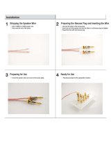
Bare wire cable ends:
Carefully remove sufficient insulation from the cable
ends, refer to figures
23, 24 & 25. If the
cable is stranded,
carefully twist the
strands together as tightly as possible.
Notes: 1. If desired, the twisted ends can be tinned
with solder to keep the strands together.
2. The prepared bare wire cable ends may be
inserted into spade lug connectors.
3. Banana plugs are for use in the United
States and Canada only.
Banana Plugs for cable ends:
1. Attach the previously prepared bare
wire cable ends into the banana plugs
and secure the connections. Refer to
f ig u re F.
2. Rotate the top of the Output Terminal
Post clockwise until it is nger tight.
Refer to gure G. Then using the
McIntosh Wrench, rotate the top of
the Output Terminal one quarter of
a turn (90° ). Do not over tighten.
Refer to gure E.
3. Referring to figure H
and the illustration on
the next page, connect
the Loudspeaker hookup
cables with banana plugs
into the hole at the end of the Input Terminal.
Note: It is important to maintain the correct polarity
at both ends of the Loudspeaker cables.
Spade Lug or Wire Connections:
1. Insert the spade lug connector or prepared section
of the cable end into the Input Terminal side access
Figure 23
Figure 24 Figure 25
Figure A
Opening
Figure B
Figure C Figure D
Figure E
Figure F
Figure H
Figure G
Figure F
Figure H
Power
Control
IN OUT
Figure 22
How to Connect with One Power Amplifier
Caution: Do not connect the AC Power Cord to the Power
Amplifier Rear Panel until after the Loudspeak-
er Connections are made. Failure to observe
this could result in Electric Shock.
The connection instructions below, together with the
XRT2.1K Connection Diagram located on the separate
folded sheet “Mc2A”, is an example of a typical audio
system. Your system may vary from this, however the
actual components would be connected in a similar
manner.
Power Control Connection:
1. For Remote Power Control, connect a power control
cable from the Audio Preamplifier or A/V Control
Center Power Control Output 1 (TRIG 1) to the
Amplifier POWER CONTROL IN.
2. Connect a power control cable from the Power
Amplifier POWER CONTROL OUT
to the XRT2.1K POWER CONTROL
IN. Refer to figure 22.
3. Connect a power control cable from the
XRT2.1K POWER CONTROL OUT
to the next XRT2.1K POWER CON-
TROL IN.
Audio XLR Cable Connection:
1. Connect an XLR cable from the Balanced Output
1 Left Channel, (refer to note 2 below) of an Audio
Preamplifier or A/V Processor, to the Amplifier
BALANCED INPUT. Place the INPUT MODE
Switch in the BALanced Position.
Note: 1. An optional hookup is to use an unbalanced
cable and place the INPUT MODE Switch in
the UNBALanced Position.
2. When multiple Power Amplifiers are used,
match up the Preamplifier or A/V Processor
Channel Output designation to each Power
Amplifier with the Loudspeaker and the
Loudspeaker location in the room.

11
hole, and tighten the Input Terminal cap until the
cable is firmly clamped into the terminals so the
lugs or wire cannot slip out. Refer to figures
I and J.
Note: It is important to maintain the correct polar-
ity at both ends of the Loudspeaker cables.
The XRT2.1K Loudspeaker is a Four Way Crossover-
System that has three pairs of Input Terminals (Posi-
tive and Negative) for connection to a Power Ampli-
fier.
XRT2.1K Loudspeaker Four Way System
Frequency Range Loudspeaker Drivers
Input Terminal
Connections
12Hz - 150Hz 8 inch Woofers SUBWOOFER
150Hz - 450Hz 6.5 inch Midrange LOW
450Hz -2,100Hz 2.0 inch Midranges MD/HIGH
2,100Hz - 45,000Hz 3/4 inch Tweeters MD/HIGH
Referring to the Connection Diagram located on the
separate folded sheet “Mc2A”, there is one Power
Ampifier with three pairs of indentical Output Termi-
nals.
Note: If the single power amplifier used only has one
pair of Output Terminals, then use the four Jump-
er Cables supplied with XRT2.1K for connection
between its three pairs of Input Terminals.
Connections To One Power Amplifier
Loudspeaker Connection with One Power Amplifier
Figure I
Figure J
1. Connect a cable from the Power Amplifier “A”
Output Terminal Positive (+) 8 Ω Terminal to the
XRT2.1K Positive (+) 8 Ω “MID/HIGH” Terminal.
Then connect a cable from the Power Amplifier “A”
Output Terminal Negative (-) 8 Ω Terminal to the
XRT2.1K Negative (-) “MID/HIGH” Terminal.
2. In a similar manner, connect a cable from the
Power Amplifier “B” Output Terminal Positive
(+) 8 Ω Terminal to the XRT2.1K Positive (+) 8 Ω
“LOW” Terminal. Then connect a cable from the
Power Amplifier “B” Output Terminal Negative (-)
8 Ω Terminal to the XRT2.1K Negative (-) “LOW”
Ter mi nal.
3. Also connect a cable from the Power Amplifier “C”
Output Terminal Positive (+) 8 Ω Terminal to the
XRT2.1K Positive (+) 8 Ω “SUBWOOFER” Termi-
nal. Then connect a cable from the Power Amplifier
“C” Output Terminal Negative (-) 8 Ω Terminal to
the XRT2.1K Negative (-) “SUBWOOFER” Termi-
nal.

12
Caution: Do not connect the AC Power Cord to the
Power Amplifiers Rear Panel until after the
Loudspeaker Connections are made. Failure to
observe this could result in Electric Shock.
The connection instructions below, together with the
XRT2.1K Connection Diagram located on the separate
folded sheet “Mc2B”, is an example of a typical audio
system. Your system may vary from this, however the
actual components would be connected in a similar
manner.
Note: When multiple Power Amplifiers are used to
drive the various sections of the XRT2.1K, it is
important that each of the amplifiers utilized
have the same amplifier gain values.
Power Control Connection:
1. For Remote Power Control, connect a power control
cable from the Audio Preamplifier or A/V Control
Center Power Control Output 1 (TRIG 1) to the
Room Correction Equalizer POWER CONTROL
IN.
2. Connect a power control cable from the Room Cor-
rection Equalizer POWER CONTROL
OUT to Power Amplifier A POWER
CONTROL IN.
3. Connect a power control cable from the
Power Amplifier A POWER CON-
TROL OUT to Power Amplifier B
POWER CONTROL IN.
4. Connect a power control cable from Power Ampli-
fier B POWER CONTROL OUT the XRT2.1K
POWER CONTROL IN. Refer to figure 22.
5. Connect a power control cable from the XRT2.1K
POWER CONTROL OUT to the next XRT2.1K
POWER CONTROL IN.
Audio XLR Cable Connection:
1. Connect an XLR cable from the Balanced Output
1 Left Channel of an Audio Preamplifier or A/V
Processor to the Room Correction Equalizer BAL-
anced IN PUT.
2. Connect an XLR cable from the Room Correction
Equalizer Balanced Output 2 Low Pass Crossover to
Power Amplifier A, BALANCED INPUT. Place the
INPUT MODE Switch in the BALanced Position.
3. Connect an XLR cable from the Room Correction
Equalizer Balanced Output 1 High Pass Crossover
to Power Amplifier B, BALanced INPUT. Place the
INPUT MODE Switch in the BALanced Position.
Loudspeaker Input Terminals:
When connecting the Loudspeaker Hookup Cables to
the XRT2.1K Loudspeaker Input
Terminals please follow the steps
below:
1. Rotate the end of the Input Ter-
minal Post counterclockwise
until an opening appears. Refer
to gures A and B.
2. Insert the Loudspeaker hookup
cable into the Input Terminal
Post opening or the cable spade
lug around the center post of the
Input Terminal. Refer to gure
C.
3. Rotate the end of the Input Ter-
minal Post clockwise until it is
nger tight. Refer to gure D.
4. Place the supplied McIntosh
Wrench over the end of the
Input Terminal and rotate it one
quarter of a turn (90° ) to secure
the Loudspeaker Cable Connection. Do not over
tighten.
Refer to gure E.
Preparing the Loudspeaker Hookup Cables:
When connecting a XRT2.1K Loudspeaker to an
amplifier, it is very important to use cables of ad-
equate size, so there is little to no power loss in the
cables. The size is specified in Gauge Numbers or
AWG (American Wire Gauge). The smaller the Gauge
number, the larger the wire size:
Loudspeaker Cable Distance vs Wire Gauge Guide
Loudspeaker
Impedance
25 feet
(7.62 meters)
or less
50 feet
(15.24 me-
ters)
or less
100 feet
(30.48 meters)
or less
8 Ohms
16AWG 14AWG 12AWG
Bare wire cable ends:
Carefully remove sufficient insulation from the cable
ends, refer to figures
23, 24 & 25. If the
cable is stranded,
carefully twist the
strands together as tightly as possible.
Notes: 1. If desired, the twisted ends can be tinned
with solder to keep the strands together.
2. The prepared bare wire cable ends may be
inserted into spade lug connectors.
3. Banana plugs are for use in the United
States and Canada only.
Banana Plugs for cable ends:
1. Attach the previously prepared bare
wire cable ends into the banana plugs
and secure the connections. Refer to
f ig u re F.
Figure 23
Figure 24 Figure 25
Figure A
Opening
Figure B
Figure C Figure D
Figure E
Figure F
Figure H
Power
Control
IN OUT
Figure 22
How to Connect with Two Power Amplifi-
ers and Room Correction Equalizer

13
2. Rotate the top of the Output Terminal Post clock-
wise until it is nger tight. Refer to
gure G. Then using the McIntosh
Wrench, rotate the top of the Output
Terminal one quarter of a turn (90° ).
Do not over tighten. Refer to gure
E.
3. Referring to figure H connect the Loudspeaker
hookup cables with ba-
nana plugs into the hole
at the end of the Input
Ter mi nal.
Note: It is important to
maintain the correct polarity at both ends of
the Loudspeaker cables.
Spade Lug or Wire Connections:
1. Insert the spade lug connector or prepared section
of the cable end into the Input Terminal side access
hole, and tighten the Input Terminal cap until the
cable is firmly clamped into the terminals so the
lugs or wire cannot slip out. Refer to figures
I and J.
Note: It is important to maintain the correct polar-
ity at both ends of the Loudspeaker cables.
The XRT2.1K Loudspeaker is a Four Way Crossover-
System that has three pairs of Input Terminals (Posi-
tive and Negative) for connection to a Power Ampli-
fier.
XRT2.1K Loudspeaker Four Way System
Frequency Range Loudspeaker Drivers
Input Terminal
Connections
12Hz - 150Hz 8 inch Woofers SUBWOOFER
150Hz - 450Hz 6.5 inch Midrange LOW
450Hz -2,100Hz 2.0 inch Midranges MD/HIGH
2,100Hz - 45,000Hz 3/4 inch Tweeters MD/HIGH
Referring to the Connection Diagram located on the
separate folded sheet “Mc2B”, there are two Power
Ampifiers each with one pair of Output Terminals.
Note: If Power Amplifier A has only one pair of 8 Ω
Output Terminals, then use two Jumper Cables
supplied with XRT2.1K for connection between
the “Subwoofer” and “Low” Loudspeaker Input
Terminals.
1. Connect a cable from the Power Amplifier A Posi-
tive (+) 8 Ω Output Terminal to the XRT2.1K Posi-
tive (+) “SUBWOOFER” Terminal. Then connect
a cable from the Power Amplifier A 8 Ω Negative
(-) Output Terminal to the XRT2.1K Negative (-)
“SU BWOOFER” Ter m i nal.
2. Connect a cable from the Amplifier “B” Positive (+)
8 Ω Output Terminal to the XRT2.1K Positive (+)
“MID/HIGH” Terminal. Then connect a cable from
the Amplifier “B” 8 Ω Negative (-) Output Terminal
to the XRT2.1K Negative (-) “MID/HIGH” Termi-
nal.
Connections To Two Power Amplifiers
Figure F
Figure H
Figure G
Loudspeaker Connection with Two Power Amplifiers and Room Correction Equalizer
Figure I
Figure J

14
Caution: Do not connect the AC Power Cord to the
Power Amplifiers Rear Panel until after the
Loudspeaker Connections are made. Failure to
observe this could result in Electric Shock.
The connection instructions below, together with the
XRT2.1K Connection Diagram located on the separate
folded sheet “Mc2C”, is an example of a typical audio
system. Your system may vary from this, however the
actual components would be connected in a similar
manner.
Note: When multiple Power Amplifiers are used to
drive the various sections of the XRT2.1K, it is
important that each of the amplifiers utilized
have the same amplifier gain values.
Power Control Connection:
1. For Remote Power Control, connect a power control
cable from the Audio Preamplifier or A/V Control
Center Power Control Output 1 (TRIG 1) to the
Room Correction Equalizer POWER CONTROL
IN.
2. Connect a power control cable from the Room Cor-
rection Equalizer POWER CONTROL
OUT to Power Amplifier A POWER
CONTROL IN.
3. Connect a power control cable from the
Power Amplifier A POWER CON-
TROL OUT to Power Amplifier B
POWER CONTROL IN.
4. Connect a power control cable from Power Ampli-
fier B POWER CONTROL OUT to Power Ampli-
fier C POWER CONTROL IN.
5. Connect a power control cable from Power Ampli-
fier C POWER CONTROL OUT the XRT2.1K
POWER CONTROL IN. Refer to figure 22.
6. Connect a power control cable from the XRT2.1K
POWER CONTROL OUT to the next XRT2.1K
POWER CONTROL IN.
Audio XLR Cable Connection:
1. Connect an XLR cable from the Balanced Output
1 Left Channel of an Audio Preamplifier to Power
Amplifier A BALANCED IN. Place the INPUT
MODE Switch in the BALanced Position.
2. Connect an XLR cable from Power Amplifier A
BALANCED OUT to Power Amplifier B, BAL-
anced IN. Place the INPUT MODE Switch in the
BALanced Position.
3. Connect an XLR cable from Power Amplifier B
BALanced OUT to Power Amplifier C, BALanced
IN. Place the INPUT MODE Switch in the BAL-
anced Position.
Loudspeaker Input Terminals:
When connecting the Loudspeaker Hookup Cables
to the XRT2.1K Loudspeaker Input Terminals please
follow the steps below:
1. Rotate the end of the Input Terminal Post counter-
clockwise until an opening ap-
pears. Refer to gures A and B.
2. Insert the Loudspeaker hookup
cable into the Input Terminal
Post opening or the cable spade
lug around the center post of
the Input Terminal. Refer to
gure C.
3. Rotate the end of the Input Ter-
minal Post clockwise until it is
nger tight. Refer to gure D.
4. Place the supplied McIntosh
Wrench over the end of the
Input Terminal and rotate it one quarter of a turn
(90° ) to secure the Loud-
speaker Cable Connection.
Do not over tighten.
Refer to gure E.
Preparing the Loudspeaker Hookup Cables:
When connecting a XRT2.1K Loudspeaker to an
amplifier, it is very important to use cables of ad-
equate size, so there is little to no power loss in the
cables. The size is specified in Gauge Numbers or
AWG (American Wire Gauge). The smaller the Gauge
number, the larger the wire size:
Loudspeaker Cable Distance vs Wire Gauge Guide
Loudspeaker
Impedance
25 feet
(7.62 meters)
or less
50 feet
(15.24 me-
ters)
or less
100 feet
(30.48 meters)
or less
8 Ohms
16AWG 14AWG 12AWG
Bare wire cable ends:
Carefully remove sufficient insulation from the cable
ends, refer to figures
23, 24 & 25. If the
cable is stranded,
carefully twist the
strands together as tightly as possible.
Notes: 1. If desired, the twisted ends can be tinned
with solder to keep the strands together.
2. The prepared bare wire cable ends may be
inserted into spade lug connectors.
3. Banana plugs are for use in the United
States and Canada only.
Banana Plugs for cable ends:
1. Attach the previously prepared bare wire cable
ends into the banana plugs and secure the connec-
Figure 23
Figure 24 Figure 25
Figure A
Opening
Figure B
Figure C Figure D
Figure E
Power
Control
IN OUT
Figure 22
How to Connect with Three Power Ampli-
fiers

15
Loudspeaker Connection with Three Power Amplifiers
tions. Refer to figure F.
2. Rotate the top of the Output Terminal
Post clockwise until it is nger tight.
Refer to gure G. Then using the
McIntosh Wrench, rotate the top of the
Output Terminal one quarter of a turn
(90° ). Do not over tighten. Refer to
gure E.
3. Referring to figure H to connect the
Loudspeaker hookup cables with ba-
nana plugs into the hole
at the end of the Input
Ter mi nal.
Note: It is important
to maintain the
correct polarity at
both ends of the Loudspeaker cables.
Spade Lug or Wire Connections:
1. Insert the spade lug connector or prepared section
of the cable end into the Input Terminal side access
hole, and tighten the Input Terminal cap until the
cable is firmly clamped into the terminals so the
lugs or wire cannot slip out. Refer to figures
I and J.
Note: It is important to maintain the correct polar-
ity at both ends of the Loudspeaker cables.
The XRT2.1K Loudspeaker is a Four Way Crossover-
System that has three pairs of Input Terminals (Posi-
tive and Negative) for connection to a Power Ampli-
fier.
XRT2.1K Loudspeaker Four Way System
Frequency Range Loudspeaker Drivers
Input Terminal
Connections
12Hz - 150Hz 8 inch Woofers SUBWOOFER
150Hz - 450Hz 6.5 inch Midrange LOW
450Hz -2,100Hz 2.0 inch Midranges MD/HIGH
2,100Hz - 45,000Hz 3/4 inch Tweeters MD/HIGH
Referring to the Connection Diagram located on the
separate folded sheet “Mc2C”, there are three Power
Ampifiers each with one pair of Output Terminals.
1. Connect a cable from the Power Amplifier A Posi-
tive (+) 8 Ω Output Terminal to the XRT2.1K Posi-
tive (+) “SUBWOOFER” Terminal. Then connect
a cable from the Power Amplifier A 8 Ω Negative
(-) Output Terminal to the XRT2.1K Negative (-)
“SU BWOOFER” Ter m i nal.
2. Connect a cable from the Power Amplifier B
Positive (+) 8 Ω Output Terminal to the XRT2.1K
Positive (+) “LOW” Terminal. Then connect a cable
from the Power Amplifier B 8 Ω Negative (-) Out-
put Terminal to the XRT2.1K Negative (-) “LOW”
Ter mi nal.
3. Connect a cable from the Power Amplifier C
Positive (+) 8 Ω Output Terminal to the XRT2.1K
Positive (+) “MID/HIGH” Terminal. Then connect
a cable from the Power Amplifier C 8 Ω Negative
(-) Output Terminal to the XRT2.1K Negative (-)
“MID/HIGH” Terminal.
Connections To Three Power Amplifiers
Figure F
Figure H
Figure G
Figure F
Figure H
Figure I
Figure J

16
Specifications
Specifications General Specifications
System Driver Complement
Six 8 inch Woofers
Two 6.5 inch Low Frequency Midranges
Twenty-eight 2 inch Upper Frequency Midranges
Forty-five 3/4 inch Dome Tweeter
Impedance
8 Ohms Nominal
Frequency Response
12Hz - 45,000Hz
Sensitivity
90 dB (2.83V/1m equivalent)
Crossover Frequencies
150Hz
450Hz
2,100Hz
Maximum Power Handling
2,100 Watts
McIntosh Logo Power Requirement
5VDC to 12VDC at 1mA
Enclosure Finish
Brushed Aluminum and black Aluminum, High Gloss
Black Top, Front and Bottom Base
Grille Finish
Black Knit Cloth with High Gloss Trim
Overall Dimensions
Height is 83-7/32 inches (211.2cm)
Width is 22-11/16 inches (57.6cm)
Depth is 25-27/32 inches (65.6cm) including cables
and connectors
Weight
353.2 pounds (160.2 kg) net
467.8 pounds (212.2 kg) in shipping carton

17

18
In the event it is necessary to repack the XRT2.1K
Loudspeaker for shipment, it must be packed exactly
as shown. To protect the finish of the Loudspeaker and
the Grille Covers it is advisable to use the cloth covers
saved when it was unboxed. If the Loudspeaker Cloth
Covers and Grille Covers are no longer available,
then wrap the Loudspeaker and Grilles with a durable
plastic film. Then place the wrapped Loudspeaker and
Grille into the protective foam packing materal, before
inserting it into the shipping carton.
Use the original shipping carton and interior parts
only if they are all in good serviceable condition. If a
shipping carton or any of the interior parts are needed,
please call or write the Customer Service Department
of McIntosh Laboratory. Refer to page 2. Please see
the Part List for the correct part numbers.
Tweeter/Midrange Column Packing
Quantity Drawing Number Part Number
1 IMB250011 310601SP
1 IMB250012 310602SP
2 IMB250013 310603SP
2 IMB250014 310604SP
1 IMB250015 310605SP
Upper Bass Column Packing
Quantity Drawing Number Part Number
1 IMB250007 310615SP
1 IMB250008 310616SP
2 IMB250009 310617SP
2 IMB250010 310618SP
XRT2.1K Packing Instructions
IMB250011
IMB250014
IMB250015
IMB250014
IMB250012
IMB250013
IMB250013
Tweeter/Midrange Column Packing
Lower Bass/Midrange Column Packing
Quantity Drawing Number Part Number
1 IMB250001 310606SP
1 IMB250002 310607SP
1 IMB250003 310608SP
1 IMB250004 310609SP
1 IMB250005 310610SP
1 IMB250006 310611SP
1 IMB250016 310612SP
1 IMB250017 310613SP
1 IMB250018 310614SP

19
XRT2.1K Packing Instructions
IMB250001
IMB250002
IMB250003
IMB250005
IMB250004
IMB250006
IMB250016
IMB250017
IMB250018
IMB250007
IMB250008
IMB250009
IMB250010
IMB250009
IMB250010
Upper Bass Column Packing
Lower Bass/Midrange Column Packing

The continuous improvement of its products is the
policy of McIntosh Laboratory Incorporated who
reserve the right to improve design without notice.
Printed in the U.S.A.
McIntosh Laboratory, Inc.
2 Chambers Street
Binghamton, NY 13903
www.mcintoshlabs.com
McIntosh Part No. 04180000
/