Page is loading ...

DUAL VOLTAGE
ICE BOX
CONVERSION SYSTEM
OWNER
,
S
GUIDE
MODELS
120 VOLTS A.C. & 12/24 VOLTS D.C.
SCQT
-
4408F
-
L
SCQT
-
4408F
-
General
This appliance is designed to convert a sailboat ice box to a mechanically refrigerated
box. The conversion unit is available in a 40 watt system and can operate on both A.C.
and D.C. power supplies. Unlike a standard self contained refrigerator, the cooling plate
is separated from the compressor / condenser unit by exible refrigerant lines. The
conversion requires installing the cooling plate in the ice box and installing the compre-
ssor / condenser unit in a well ventilated location within the 3.6m of available refrigerant
tubing.
CAUTION
Specification
A.
Identification of parts
-
unpack the conversion unit and check for damaged or missing
parts.
Exterior Dimensions
Dimensions of Evaporator
Length of Suction Tube
Length of A.C. Cord
Length of D.C.Cord
Length of Thermistor Cord
Exterior Dimensions
1. Never store gasoline or other amable vapors and liquids as these sometimes cause
explosion.
2. Do not touch evaporator and metal parts of cabinet inside by wet hand. Sometimes, it
may cause frostbite to your hand.
3. Do not remove modify all the electrical live parts to avoid electric shock and trouble of
your refrigerator.
Thermostat Box:
Evaporator Standoff
Accessories:
B.
Required Tools
C.
Location of Components
D.
Installation
6.4mm dia Drill and Assorted Bits
32mm dia Hole Saw
21mm and 24mm Wrenches or 2 Adjustable
Wrenches
Phillips and Straight Screwdrivers
Wire Cutters and/or Wire Strippers
Electrician Tape and Wire Connectors
Tube of Silicone
Before the installation work is begun, the layout of the entire system should be
considered, with particular attention to the following points
a. Location and position of the cooling plate.
b. Point of tubing exit from ice box.
c. Thermostat mounting position.
d. Route of refrigerant tubing.
e. Location of compressor/condenser unit.
For the purpose of keeping a sufcient circulation of refrigeration oil;
Altitude of compressor to evaporator
There are two basic positions which are acceptable for the cooling plate as shown
in Fig. 3
(
a
)
. Positions shown in Figs. 3
(
b
),(
c
)
or 3
(
f
)
will result in unacceptable cooling
performance. For top opening boxes, the position as shown in Fig.3
(
a
)
is the most
common. It is preferable to install the cooling plate
(
s
)
as high in the box as possible to
obtain good circulation of cold air and more uniform temperatures. Placement of the
compressor/condenser is very important, since ventilation is a major consideration. The
unit depends upon the convection air around it to remove its heat.
Set the evaporator within 50cm in altitude to the compressor head if the evaporator
is installed at higher position than the compressor.
Availability of space for the compressor/condenser is usually found beneath or behind
the companion way, lazaretto, quarter berth or settee.
At times, the engine compartment may be considered but many times not recommended
because of the heat produced from the engine. The important point is that the space
must be well ventilated. If the location is closed to air movement, it may be possible to
cut openings in panels and, if necessary, provide louvered panels (available at marine
supply).
The best venting arrangement in a conned space is to provide an opening below, or
low on the side, and an opening at the top, or high on the side.
The size of the lower and upper openings should be an equivalent of 650 square cm
minimum free opening for each.
See Fig 4. Allow several inches on each side and top of the unit for accessibility and
ventilation.
Before the compressor/condenser location is selected, measure the exact route of the
refrigerant tubing to insure the unit is within reach.
Also, the top of the compressor/condenser unit must not be installed higher than 50 cm
above the cooling plate to insure sufcient circulation of refrigerant oil.
Before deciding on the compressor/condenser location, there should be assurance that
the electrical wiring will be accessible to the unit, both A.C. and D.C. supplies.
DO NOT PLACE THE COMPRESSOR/CONDENSER IN A CONFINED SPACE WHICH RECEIVES
NO VENTILATION.
IMPORTANT
DIRECTIONS
FOR
TUBE
BENDING
ORIGINAL
STATE
(
AS RECEIVED
)
a.
b.
c.
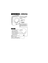
The copper suction tube is clamped at the
nearest point to the Evaporator.
(
Refer to Figure 1, Point A.
)
The tube is bent in a tight U-shape at
Point “B”.
(
Refer to Figure 1, Point B.
)
The remaining part of the tube to the
connecting coupler is rolled in a large
diameter “L”.
(
Refer to Figure 1, “L”.
)
DIRECTIONS
FOR
UNCOILING
SUCTION
TUBE
a. Carefully straighten the coiled tube indicated by “L” so that the tube position
is similar to the position shown in Figure 2.
Fig. 1
A
B
L
b.
c.
When the Evaporator is installed into
the cabinet, retain the tight U-shape
bend indicated at point “B”. The tube
section at “C” must not be moved or
altered so as to protect the connector
to the Evaporator as indicated by point
“D”.
In case the installation requires the tube
to be run in Direction “E”, then use
Figure 2 as a guide.
On the other hand, if the tube is to be
run in another direction
(
G, F, H, I
)
,
carefully bend the tube at point “K”.
For reference, the type of bend for
various directions
(
G, F, H, I
)
is shown
where “K” is the point of bending.
In case of “G” direction.
In case of “F” direction.
In case of “H” direction.
In case of “I” direction.
Important
Insert the evaporator in storage compartment and secure it
(
with screws provided
)
on the vertical side wall of the compartment using the evaporator standoff.
(
Fig.
2
)
.
Do not kink or excessively bend tubing since this can not only cause damage but
can restrict free ow of refrigerant.
Cover the suction tube with insulation material, such as neoprene sponge, tube or
berglass tape, outside of the refrigerating box.
1.
Remove dust caps and plugs if used, making sure that components synthetic seals
are intact. It is best to complete connection to the lower coupling before making
the next connection.
Wipe off coupling seals and threaded surfaces with a clean cloth to prevent the
inclusion of dirt or any foreign material in the system.
Lubricate rubber seal in made half with a thin coat of oil. Thread coupling halves
together by hand to insure proper mating of threads.
1.
2.
3.
The compressor/condenser case can be easily mounted to the oor mounting
brackets and by use of screws or bolts,
(
Fig 6
)
Place unit to insure accessibility and
good circulation
(
see paragraph on location
)
.
Set the thermostat box side wall of the refrigerating box, within reach, referring
to
(
Fig. 7
)
Turn the thermostat control knob to the “off” position.
With the power supplies off, make the electrical connections, referring to
(
Fig. 9
)
.
Refer to
WIRE SIZE
table for recommended D.C. wire sizes.
2.
3.
In making the tube bend at
point “K”, a tube bending
tool should be used. If not
available, the tube can be
hand bent using a wooden
or metal cylindrical shape of
approximately 50-65mm
diameter.
Caution
Use extreme care in hand bending so as not to
kink, atten or damage the copper tube.
Caution
IN CASE OF “G” DIRECTION
Fig. 2
B
C
D
E
E
F
F
G
G
I
H
B
B
B
B
B
H
I
K
K
K
K
(
2 in DIA
)
B
B
The refrigerant quick connect couplings must be kept clean and dry. Do
not remove dust caps and plugs until ready to make the connections.
E.
Important The D.C. wire connection should be made to a dedicated 12/24 volts supply
with a circuit breaker. This 12/24 volts must be a battery -not a converter
or battery charger.
See
(
Fig. 10
)
.
Note
F.
Connection of Refrigerant Couplings
one set of couplings connects to the mating set on the compressor/
condenser unit. The threads are such that the two lines cannot be
reversed.
At this point make sure two proper sized wrenches are available, since
the tightening should be done rapidly to minimize any refrigerant loss
(
you may hear a brief “hiss” as the joint is tightened
)
.
CAUTION
Always turn the female coupling and hold the male coupling with the
second wrench.
Use proper size wrenches
(
on coupling body hex and union nut
)
and tighten until
coupling bodies “bottom” or denite resistance is felt.
Using a maker or ink pen, mark a line lengthwise from the coupling hex to the
bulkhead. Then tighten an additional 1/6 to 1/4 turn.
The misalignment of the line will show the degree of tightening.
The nal turn is necessary to insure that the knife edge metal seal bites into the
brass seat of the coupling halves, forming the leakproof joint. If torque wrench
is used, the following torque values are recommended.
Coupling Size No. 6; Torque 230kgf. cm-270kgf. cm
After all couplings are tight, leak check the joint with a soap solution.
G.
Connecting to Power Source
Your refrigerator can be operated on A.C.
(
120 volts
)
from the wall socket or D.C.
(
12/24 volts
)
from a battery. 12/24 volts D.C. Operation in Your Boat, Trailer, Camper,
Etc.
The car battery voltage varies with the type of car you own. Most cars and boats
use a 12 volts system. Your refrigerator needs a 12/24 volts battery. See
(
Fig. 10
)
If the battery voltage is too high
(
for example 32 volt
)
your refrigerator can not
cool On the other hand, its cooling power will decrease if the voltage is
lower than 12 volts.
Set the thermostat control knob to “OFF”. Connect two
(
2
)
wires from the
battery, REFERRING TO PLUS/MINUS
(
+
/
−
)
INDICATIONS.
The battery must have a charging means available, such as a generator, converter
or the alternator. If not, the battery will discharge in a short period of time.
Any switches, lead wires or other electrical equipment should not be common
with wiring between your refrigerator and battery, because this equipment often
generates high voltage pulses and causes transistor trouble in the power − supply.
See
(
Fig. 10
)
.
CAUTION
CONNECT REFRIGERATOR DIRECT TO BATTERY
On D.C. operation, connecting the D.C. supply properly to the refrigerator is impor-
tant. You will note that one lead wire is marked
(
+
)
positive and the other
(
−
)
neg-
ative.
If the polarity be reversed, The unit does not operate and does not light thermostat
lamp, check the fuse located in D.C. lead and the polarity of the D.C. power
supply.
If it still does not operate, this is an indication that other problem exist in the
inverter, and the unit should be checked by an authorized Norcold Service Center.
To reduce the radio interference and induction of a high surge voltage from the
outside, twisting of the lead wire is important. See
(
Fig. 11
)
.
H.
Operational Check
After completing the nal installation details, an operational check can be made by
watching the thermostat control knob to “ON” and turning the temperature control
dial from 1 to 5 until the compressor starts. After a few minutes, the cooling
plates should feel cold indicating circulation of refrigerant. Check on both A.C. and
D.C. operation.
NOTE Built in relay switches automatically to correct power supply.
Suppose the refrigerator is operating on 120 volts A.C.
(
shore-power
connection on boat dock, etc.
)
and then the power source is disconnected
by a switch or by pulling the plug, the relay automatically switches the
refrigerator over to the 12/24 volts D.C. power source and continues to operate
the compressor, providing, of course, the leads are connected to the battery.
If the refrigerator is operating normally on a 12/24 volts battery, then, when 120
volts A.C. power is switched on or by just plugging in the A.C. power cord,
the relay switches the compressor over to A.C. operation. This will save on
power consumption and keep your battery in good condition. Refrigerating
temperature can be controlled by means of the temperature control dial.
The interior temperature drops as the dial position is changed from “1” to “5”.
In this way, interior temperatures can be regulated freely within the range of
7.2°C to 0°C. To switch off your refrigerator, move the thermostat control
knob to “OFF”. The dial does not turn clockwise beyond “1” and “5”.
For efcient operation, regulate the temperature according to the types of
foods stored.
MAINTENANCE OF BATTERY IS IMPORTANT
If the charge of your battery is not sufcient, a decline in the cooling perfor-
mance of your refrigerator can be expected. If 120 V, electric power supply is
available, A.C. operation is recommended to keep your battery in good
condition. A.C. power is AUTOMATICALLY applied, if your vehicle's 120 volts
electric system is connected to the outside 120 V power supply.
NEVER EMPLOY A “QUICK CHARGER” TO YOUR BATTERY UNLESS THERMOSTAT
POWER SWITCH HAS BEEN TURNED TO “OFF”.
a.
b.
c.
d.
mm
mm
m
m
cm
m
m
SCQT-4408F-L SCQT-4408F-I
SCQT-4408F-LModel
AC120V
DC12/24V
Input rating
Refrigerant
Weight
SCQT-4408F-I
406
(
L1
)
× 215
(
L2
)
× 270
(
H
)
523
(
L1
)
× 225
(
H
)
6
pieces
4
pieces
359
(
W
)
× 242
(
L
)
× 148
(
H
)
84
(
H
)
× 50
(
W
)
× 40
(
D
)
3.6
1.6
15
3.2
0.7A
2.5A/1.3A
HFC-134a
Approx. 12kg
Norcold Inc

/