Tripp Lite B022-U08-IP & B022-U16-IP Quick start guide
- Category
- KVM switches
- Type
- Quick start guide
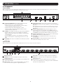
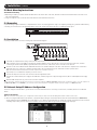
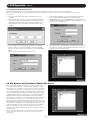
Tripp Lite B022-U08-IP & B022-U16-IP are 1U rack-mount KVM switches that allow users to control multiple computers using a single keyboard, mouse, and monitor. These switches support both USB and PS/2 connections, making them compatible with a wide range of computers.
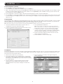
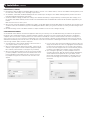
With built-in IP access, these switches can be accessed remotely via a LAN, WAN, or the Internet, allowing administrators to manage computers from anywhere. They also feature a USB 1.1 port for sharing USB peripherals among connected computers.
The switches support high-resolution video up to 2048 x 1536 at the local console and 1600 x 1200 @ 60 Hz, 24-bit color depth at the remote console. They also support a variety of operating systems, including Windows, Linux, Mac, and DOS.
Tripp Lite B022-U08-IP & B022-U16-IP are 1U rack-mount KVM switches that allow users to control multiple computers using a single keyboard, mouse, and monitor. These switches support both USB and PS/2 connections, making them compatible with a wide range of computers.
With built-in IP access, these switches can be accessed remotely via a LAN, WAN, or the Internet, allowing administrators to manage computers from anywhere. They also feature a USB 1.1 port for sharing USB peripherals among connected computers.
The switches support high-resolution video up to 2048 x 1536 at the local console and 1600 x 1200 @ 60 Hz, 24-bit color depth at the remote console. They also support a variety of operating systems, including Windows, Linux, Mac, and DOS.


-
 1
1
-
 2
2
-
 3
3
-
 4
4
-
 5
5
-
 6
6
-
 7
7
-
 8
8
-
 9
9
-
 10
10
-
 11
11
-
 12
12
-
 13
13
-
 14
14
-
 15
15
-
 16
16


Tripp Lite B022-U08-IP & B022-U16-IP Quick start guide
- Category
- KVM switches
- Type
- Quick start guide
Tripp Lite B022-U08-IP & B022-U16-IP are 1U rack-mount KVM switches that allow users to control multiple computers using a single keyboard, mouse, and monitor. These switches support both USB and PS/2 connections, making them compatible with a wide range of computers.
With built-in IP access, these switches can be accessed remotely via a LAN, WAN, or the Internet, allowing administrators to manage computers from anywhere. They also feature a USB 1.1 port for sharing USB peripherals among connected computers.
The switches support high-resolution video up to 2048 x 1536 at the local console and 1600 x 1200 @ 60 Hz, 24-bit color depth at the remote console. They also support a variety of operating systems, including Windows, Linux, Mac, and DOS.
Ask a question and I''ll find the answer in the document
Finding information in a document is now easier with AI
Related papers
-
Tripp Lite B022-U08-IP User manual
-
-
Tripp Lite B022-U08-IP & B022-U16-IP Owner's manual
-
-
-
-
-
-
-
Tripp Lite B020-U08-19-IP User manual
Other documents
-
Digitus DS-23300-1 Datasheet
-
ATEN KW1000 Quick start guide
-
Approx APPKVMUSB2P Datasheet
-
Lindy 39405 User manual
-
LevelOne Washer KVM-9000 User manual
-
D-Link KVM-410 User manual
-
-
Jasco 97764 User manual
-
Apantac KVM-16-E Installation and User Manual
-