Greenlee 7904SB & 7906SB - Serial ZA User manual
- Type
- User manual
Greenlee 7904SB & 7906SB - Serial ZA is a hydraulic punch driver used for cutting holes in various materials. It features a compact design for easy handling and access to tight spaces. The tool utilizes a closed hydraulic system and requires minimal maintenance. It comes equipped with a rubber bladder for storing hydraulic oil, ensuring a mess-free operation. Additionally, the punch driver offers adjustable rotation to accommodate different work orientations. With its durable construction and efficient operation, this tool is ideal for electrical, plumbing, and HVAC professionals.
Greenlee 7904SB & 7906SB - Serial ZA is a hydraulic punch driver used for cutting holes in various materials. It features a compact design for easy handling and access to tight spaces. The tool utilizes a closed hydraulic system and requires minimal maintenance. It comes equipped with a rubber bladder for storing hydraulic oil, ensuring a mess-free operation. Additionally, the punch driver offers adjustable rotation to accommodate different work orientations. With its durable construction and efficient operation, this tool is ideal for electrical, plumbing, and HVAC professionals.


-
 1
1
-
 2
2
-
 3
3
-
 4
4
-
 5
5
-
 6
6
-
 7
7
-
 8
8
-
 9
9
-
 10
10
-
 11
11
-
 12
12


Greenlee 7904SB & 7906SB - Serial ZA User manual
- Type
- User manual
Greenlee 7904SB & 7906SB - Serial ZA is a hydraulic punch driver used for cutting holes in various materials. It features a compact design for easy handling and access to tight spaces. The tool utilizes a closed hydraulic system and requires minimal maintenance. It comes equipped with a rubber bladder for storing hydraulic oil, ensuring a mess-free operation. Additionally, the punch driver offers adjustable rotation to accommodate different work orientations. With its durable construction and efficient operation, this tool is ideal for electrical, plumbing, and HVAC professionals.
Ask a question and I''ll find the answer in the document
Finding information in a document is now easier with AI
Related papers
-
Greenlee 7804SB / 7806SB, 7704SB / 7706SB AHJ&YZ User manual
-
-
-
-
-
-
-
-
-
Other documents
-
Thomas & Betts Gator EK22GL User manual
-
Eclipse 902-482 User manual
-
ALFRA AP-65 Operating instructions
-
 Rockford Fosgate SD-18 Owner's & Maintenance Manual
-
-
 Geotech Portable Bladder Pumps Owner's manual
-
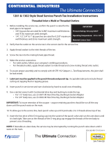 Continental Industries (CI) 0000-34-7144-50-steel-service-punch-tee Installation guide
-
 Baldor-Reliance Reducer Oil Conversion Mobil SHC634 to Kluber UH1-6-460 Owner's manual
-
Sealey VS0031 User manual
-
Lincoln Electric K2391-1 User manual


