
Brute LX
B
rute
LX
Installation and Operation Instructions Document 1295A
H2364001A
WARNING
If the information in this manual is not
followed exactly, a re or explosion may
result causing property damage, personal
injury or loss of life.
Do not store or use gasoline or other
ammable vapors and liquids in the vicinity of
this or any other appliance.
WHAT TO DO IF YOU SMELL GAS
• Do not try to light any appliance.
• Do not touch any electrical switch; do not
use any phone in your building.
• Immediately call your gas supplier from a
nearby phone. Follow the gas supplier's
instructions.
• If you cannot reach your gas supplier, call
the re department.
Installation and service must be performed
by a qualied installer, service agency, or gas
supplier.
FOR YOUR SAFETY: This product must be installed and serviced by a professional service technician,
qualied in hot water boiler and heater installation and maintenance. Improper installation and/or operation
could create carbon monoxide gas in ue gases which could cause serious injury, property damage, or
death. Improper installation and/or operation will void the warranty.
AVERTISSEMENT
Assurez-vous de bien suivres les instructions
données dans cette notice pour réduire au
minimum le risque d’incendie ou d’explosion
ou pour éviter tout dommage matériel, toute
blessure ou la mort.
Ne pas entreposer ni utiliser d’essence ou ni
d’autres vapeurs ou liquides inammables dans
le à proximité de cet appareil ou de tout autre
appareil.
QUE FAIRE SI VOUS SENTEZ UNE ODEUR DE
GAZ:
• Ne pas tenter d’allumer d’appareils.
• Ne touchez à aucun interrupteur. Ne pas vous servir
des téléphones dans le bâtiment où vous vous
trovez.
• Appelez immédiatement votre fournisseur de
gaz depuis un voisin. Suivez les instructions
du fournisseur.
• Si vous ne pouvez rejoindre le fournisseur de
gaz, appelez le sservice des incendies.
L’installation et l’entretien doivent être assurés par
un installateur ou un service d’entretien qualié
ou par le fournisseur de gaz.
Installation and Operation
Instructions for
Wall-Mounted Modulating Boiler
Model BLXH
50, 75, 100, 125, 150, 175 & 220 MBH
Combination
Boiler and Water Heater
Model BLXC
125, 150 and 175 MBH

BRADFORD WHITE CORP
.
TABLE OF CONTENTS
SECTION 1.
General Information
1.1 Introduction ........................................................ 1
1.2 To Open the Brute LX ......................................... 1
1.3 Rating Plate ........................................................ 1
1.4 Model Nomenclature........................................... 1
1.5 Brute LX Overview .............................................. 2
1.6 Start Up / Shut Down Instruction (Decal) ............ 3
1.7 Dimensions for all Sizes ..................................... 4
1.8 Unpacking ........................................................... 6
1.9 Warranty ............................................................. 6
SECTION 2.
Locating the Appliance
2.1 Locating the Appliance........................................ 7
2.2 Correct Vent Distance
from Outside Wall or Roof Termination ............... 7
2.1 Wall Mount Hole Locations ................................. 8
SECTION 3.
Venting and Combustion Air
3.1 Combustion Air ................................................... 9
3.1.1 Combustion Air from Room................................. 9
3.1.2 Ducted Combustion Air ..................................... 10
3.2 Venting (Exhaust) ............................................. 10
3.2.1 About Common Venting .................................... 12
3.3 Locating Vent & Combustion Vent Terminals .... 13
3.3.1 Side Wall Vent Terminal .................................... 13
3.3.2 Side Wall Combustion Air Terminal ................... 13
3.3.3 Vertical Vent Terminal ....................................... 15
3.3.4 Vertical Combustion Air Terminal ...................... 15
3.3.5 Installations in the Commonwealth
of Massachusetts .............................................. 15
3.4 Common Vent Test ........................................... 16
SECTION 4.
Gas Supply and Piping
4.1 Gas Supply and Piping .......................................... 17
SECTION 5.
Pump Capacity
5.1 Brute LX Heating System Pump Capacity ............. 18
SECTION 6.
Water Connections
6.1 Central Heat System Piping.............................. 19
6.2 Cold Water Make-Up ........................................ 19
6.3 Freeze Protection ............................................. 19
6.4 Recognized Chemicals ..................................... 20
6.5 Domestic Hot Water Piping (DHW and BLXC) . 20
6.6 Indirect Water Heater Piping ............................. 20
6.7 Condensate Drain ............................................. 20
6.8 Piping Schematics .......................................21-26
SECTION 7.
Electrical Connections
7.1 Main Power ....................................................... 27
7.2 Pump Connections ........................................... 27
7.3 24Vac Transformer Circuit Breaker ................... 27
7.4 Central Heat - Call for Heat .............................. 27
7.5 Outdoor Air Temperature Sensor ...................... 27
7.6 Domestic Hot Water Connection ...................... 27
7.7 System Sensor
(lead lag/cascading operation only) .................. 27
7.8 External Control Connections ........................... 27
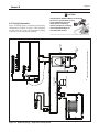
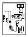
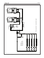
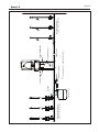
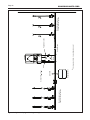
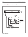
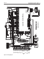
7.9 Ladder Diagram, Connections, and
Wiring Diagrams ..........................................28-30

Brute LX
SECTION 8.
CONTROL Setup and Operation
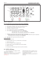
8.1 Digital Display ................................................... 31
8.2 CONTROLLER Modes ..................................... 32
8.3 User Mode ........................................................ 33
8.4 Installer Mode ................................................... 34
8.5 Service Mode .................................................... 35
8.6 Modulation Control............................................ 35
8.7 Pump Control .................................................... 35
8.8 High Limit .......................................................... 36
8.9 Stack Temperature ............................................ 36
8.10 Domestic Hot Water Temperature..................... 36
SECTION 9.
OPERATION Modes
9.1 Hydronic Heating Demand................................ 36
9.2 Hydronic Heating with Outdoor Reset .............. 36
9.3 Hydronic Heating Using External
Modulation Control............................................ 36
9.4 Warm Weather Shutdown ................................. 37
9.5 Domestic Hot Water Demand (BLXC only) ....... 37
9.6 Domestic Hot Water Priority (BLXC only) ......... 37
9.7 Cascade Auto Conguration ............................. 38
SECTION 10.
Set Up Instructions
10.1 Filling the Boiler System ................................... 39
10.2 Starting the Burner after Set Up ....................... 39
10.2.1 Burner Operation ............................................ 39
10.2.2 Boiler Setup and Adjustment .......................... 40
10.3 Shutting Down the Brute LX ............................. 40
10.4 To Restart the Brute LX .................................... 40
SECTION 11.
Maintenance
11.1 System Maintenance ....................................... 42
11.2 Appliance Maintenance and Component
Description ........................................................ 42
11.2.1 Burner ............................................................... 42
11.2.2 Appliance Control ............................................. 42
11.2.3 Ignitor Assembly ............................................... 43
11.2.4 Flame Sensor ................................................... 43
11.2.5 Blower ............................................................... 43
11.2.6 Heat Exchanger Coils ....................................... 43
11.2.7 Gas Conversion ................................................ 44
SECTION 12.
Troubleshooting
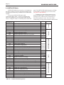
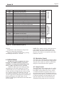
12.1 Sequence of Operation .................................... 45
12.2 Short Cycling .................................................... 45
12.3 Error Codes ...................................................... 46
SECTION 13.
Replacement Parts
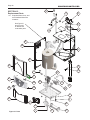
13.1 Exploded Parts Illustrations ............................. 48

BRADFORD WHITE CORP
.
THE
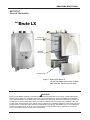
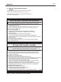
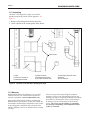
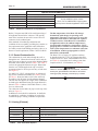
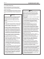
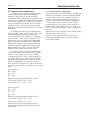
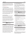
Figure 1. Opening the Brute LX.
The top and bottom panels come off when
pulled forward. This is true for all sizes.
START-UP
INSTRUCTIONS
START-UP
INSTRUCTIONS
SECTION 1.
General Information
WARNING
Brute LX units must be installed in accordance with the procedures detailed in this manual, or the Bradford White
warranty will be voided. The installation must conform to the requirements of the local jurisdiction having authority,
and, in the United States, to the latest edition of the National Fuel Gas Code, ANSI Z223.1/NFPA54. In Canada, the
installation must conform to the latest edition of CSA B149.1 Natural Gas and Propane Gas Installation Code, and/
or local codes. Where required by the authority having jurisdiction, the installation of Brute LX boilers must conform to
the Standard for Controls and Safety Devices for Automatically Fired Boilers, ANSI/ASME CSD-1. Any modications
to the boiler, its gas controls, or wiring may void the warranty. If eld conditions require modications, consult the
factory representative before initiating such modications.
WIRING
DIAGRAM
RATING PLATE
Brute LX

Page 1
Brute LX
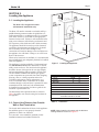
Figure 1. Opening the 100, 125, 150, 175, and 220
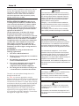
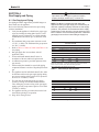
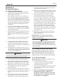
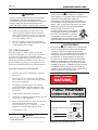
Figure 2. Model Nomenclature
2 3 4 5 6 7 8 9 10 11 12 13
L X A X N
SERIES
L
- SERIES
HEAT
EXCHANGER
LABEL
BRUTE
USAGE
H - HYDRONIC
C - COMBI
UNIT
SIZES
MBTU/h
50
75
100
125
150
175
220
FUEL
N - NATURAL
P - PROPANE
CONFIG
W - WALL
ALTITUDE
A - 0-10,000 FEET
REVISION
1 - FIRST
OPTIONS
X -
STANDARD
L -
LWCO
PUMP OPTIONS
N - WITH PUMP
1
B
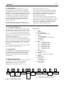
1.1 Introduction
This manual provides information necessary for the
installation, operation, and maintenance of Bradford
White Brute LX appliances. Read it carefully before
installation. All application and installation procedures
should be reviewed completely before proceeding with
the installation. Consult the Bradford White factory,
or local factory representative, with any problems or
questions regarding this equipment. Experience has
shown that most operating problems are caused by
improper installation.
All installations must be made in accordance with
1) American National Standard Z223.1/NFPA54-Latest
1.3 Rating Plate
The Rating Plate is located on the metal pan behind the
lower plastic panel. It contains Model Nomenclature,
Manufacture Date, Model Number, Serial Number,
Output Rating, and all other information pertaining to
your Brute LX. .
1.2 To Open the Brute LX
To open the Brute LX for maintenance and servicing,
the upper and lower plastic panels are designed to 'pop'
off when they are pulled forward. See Figure 1 and
Figure 3. This will expose the top metal panel which
covers the heat exchanger, and the lower panel which
holds the low voltage connections and covers the pump
and other lower components.
To remove these panels for further access into the
Brute LX, there are two screws that hold each panel in
place. Remove the 2 screws on the upper panel and slide
the upper metal panel up and out. For the lower panel,
remove the 2 screws and hinge the lower metal panel
downward.
The center panel containing the On/Off Switch, Gauges,
and User Interface is not removable.
Edition “National Fuel Gas Code” or
2) CSA B149.1 “Natural Gas and Propane Installation
Code” and with the requirement of the local utility or
other authorities having jurisdiction. Such applicable
requirements take precedence over the general
instructions contained herein.
All electrical wiring is to be done in accordance with
the local codes, or in the absence of local codes, with: 1)
The National Electrical Code ANSI/NFPA No. 70-latest
Edition, or 2) CSA STD. C22.1 “Canadian Electrical
Code - Part 1”. This appliance must be electrically
grounded in accordance with these codes.
Nomenclature
(1) Label
B = Brute
(2-3) Series Designation
LX = L Series Heat Exchanger
(4) Usage
H = Modulating Boiler
C = Combination Boiler and Water Heater
(5) Conguration
W = Wall Hung
(6-8) Size
50 = 50,000 BTU/hr input
75 = 75,000 BTU/hr input
100 = 100,000 BTU/hr input
125 = 125,000 BTU/hr input
150 = 150,000 BTU/hr input
175 = 175,000 BTU/hr input
220 = 220,000 BTU/hr input
(9) Fuel
N = Natural Gas
P = LP Gas (propane)
(10) Altitude
A = Up to10,000 Feet: de-rate applies
*
(11) Revision
1 = First version
(12) Options Code
X = Standard
L = Low water cutoff
(13) Pump Options
N = With Pump
1.4 Model Nomenclature
The Model Nomenclature is shown on your Rating Plate
and consists of a series of letters and numbers
( Nomenclature ) that further identies the
characteristics of your Brute LX. See Figure 2.
*
For high altitude applications, boiler must be
de-rated 4% per 1000 feet above 2000 feet.
*

Page 2
BRADFORD WHITE CORP
.
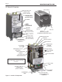
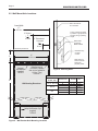
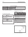
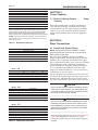
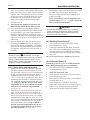
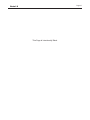
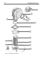
Figure 3. Location of Components
1.5 Brute LX, Overview
CENTRAL HEAT
IN CONNECTION
(RETURN WATER)
CENTRAL HEAT
IN CONNECTION
(RETURN WATER)
CENTRAL HEAT OUT
CONNECTION
(SUPPLY WATER)
CENTRAL HEAT OUT
CONNECTION
(SUPPLY WATER)
SHOWN WITH THE FRONT PANELS OFF,
AND A SIDE PANEL MISSING FOR VISUAL
PURPOSES.
COMBUSTION INLET
HEAT EXCHANGER
ASME TAG
AUTOMATIC
AIR VENT
LOW WATER CUT OFF
(OPTIONAL)
EXHAUST
SERVICE HATCH
GAS SUPPLY
HEAT EXCHANGER
WATER PRESSURE
SWITCH
USER
INTERFACE
TEMPERATURE /
PRESSURE GAUGE
GAS VALVE
PUMP
HIGH VOLTAGE
FIELD CONNECTION
TERMINALS
LOW VOLTAGE
FIELD CONNECTION
TERMINALS
FOLDS DOWN
TO OPEN
BLOCKED VENT
PRESSURE SWITCH
COMBUSTION
AIR FAN
( BLOWER )
ON / OFF
SWITCH
2 SCREWS
2 SCREWS
LIFT
DHW
HOT OUT
GAS SUPPLY
DHW
COLD IN
DHW FLAT PLATE
HEAT EXCHANGER
(COMBINATION BOILERS ONLY)
BOTTOM
VIEW
3-WAY VALVE
CONDENSATE
TRAP
USER
INTERFACE
TEMPERATURE /
ON / OFF
SWITCH
PRESSURE GAUGE
COMBUSTION INLET
GAS VALVE
HEAT EXCHANGER
HEAT EXCHANGER
HEAT EXCHANGER
HEAT EXCHANGER
HEAT EXCHANGER
HEAT EXCHANGER
CENTRAL HEAT
IN CONNECTION
CONDENSATE
CENTRAL HEAT OUT
BLOCKED VENT
PRESSURE SWITCH
AUTOMATIC
AUTOMATIC
AIR VENT
AUTOMATIC
WATER PRESSURE
WATER PRESSURE
LIFT
2 SCREWS
2 SCREWS
2 SCREWS
CENTRAL HEAT
CENTRAL HEAT OUT
GAS SUPPLY
GAS SUPPLY

Page 3
Brute LX
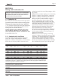
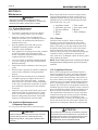
Figure 4. Start Up / Shut Down Instructions (Decal)
(3).Turn manual gas cock "off"
H23377-
qualified service technician to inspect the appliance and to replace any gas control which
C. Do not use this appliance if any part has been under water. Immediately call a
D. TO TURN OFF GAS TO APPLIANCE
(1) SET SELECTOR SWITCH TO "OFF"(0) (2) Turn off all electric power to appliance
incendie ou une explosion pourrait se produire et causer des dommages
materiels, des blessures personnelles ou meme la mort..
PAR MESURE DE PRUDECE, LISEZ CE QUI SUIT AVANT
DE FAIRE FONCTIONNER L'APPAREIL
FOR YOUR SAFETY READ BEFORE OPERATING
may result causing property damage, personal injury or loss of life.
"WARNING: If you do not follow these instuctions exectly, a fire or explosion
"MISE EN GARDE: Si vous ne suivez pas ces instructions a la lttre, un
A. This appliance does not have a pilot. It is equipped with an ignition device that
automatically lights the burner.
B. BEFORE OPERATING smell all around the appliance area for gas. Be sure to smell
next to the floor because some gas is heavier than air and will settle on the floor.
WHAT TO DO IF YOU SMELL GAS
· Do not try to light appliance.
· Do not touch any electric switch: do not use any phone in your building
· Immediately call your gas supplier from a neighbor's phone. Follow the gas
supplier's instructions.
· If you cannot reach your gas supplier, call the fire department.
has been under water
A. Cet appareil n'est pas doté d'une veilleuse. Il est équipe d'un dispositif d'allumage
qui allume automatiquement le brûleur. Ne tentez pas d'allumer le brûleur manuellement.
B. AVANT D'UTILISER, vérifiez s'il n'ya pas d'odeur de gaz prés de l'appareil. Vérifiez
s'il n'ya pas d'odeur de gaz prés du plancher, car le gaz est plus lourd que l'air et peut
se déposer sur le plancher.
QUE FAIRE EN CAS D'ODEUR DE GAZ
• N'essayez pas d'allumer n'importe quelque appareil que ce soit.
• Ne touchez pas a un commutateur electrique. N'utilisez pas le téléphone de votre résidence.
• Appelez immédiatement votre fournisseur de gaz en utilisant le téléphone de votre
voisin. Suivez les instructions de votre fournisseur de gaz.
• Si vous ne pouvez joindre votre fournisseur de gaz, appelez le service des incendies.
C. N'utilisez pas cet appareil si l'une des pièces a été plongée sous l'eau.
Communiquez immédiatement avec un technicien de service qualifie afin qu'il inspecte
l'appareil et remplace toute pièce du système de commande et toute commande de
gaz qui aurait été plongée sous l'eau.
D. FERMETURE DE L'ALIMENTATION EN GAZ
(1) Poussez le bouton a bascule vers La position OFF (0).
(2) Coupez l'alimentation électrique â l'affairée.
(3) fermez le robinet de gaz manuellement vers OFF (la poignée est horizontale
1.6 Start Up / Shut Down Instructions
(Decal)
The Start Up / Shut Down Instruction (Decal) can be found
on the metal panel behind the Top Panel. See Figure 1.
This Decal is also referred to as the Operating Instructions
Label and/or Warning Label.

Page 4
BRADFORD WHITE CORP
.
3
1
4
"
8
3
1
4
"
8
7
3
4
"
20
N
17"
43
TOP
M
O
8
3
4
"
22
2
3
4
"
7
GAS
GAS
HYDRONIC
OUTLET
HYDRONIC
OUTLET
ELIMINATION
AIR
AIR
VENT
INLET
EXHAUST
VENT
HYDRONIC
INLET
HYDRONIC
INLET
H
F
G
E
A
D
C
CONDENSATE
TRAP
MASCOT LX BOILER
MODELS, PIPING
INSTALL LOCATION
DIM A
HYDRONIC
OUT
DIM B
HYDRONIC
OUT
DIM C
HYDRONIC
IN
DIM D
HYDRONIC
IN
DIM E
GAS
DIM F
GAS
DIM G
CONDENSATE
OUTLET
DIM H
CONDENSATE
OUTLET
DIM J
DHW OUT
DIM K
DHW OUT
DIM J
DHW IN
DIM L
DHW IN
DIM M
CABINENT
HEIGHT
DIM N
CABINENT
DEPTH
75,000 BTU 1" (3) 15-3/4" (40) 3-3/4" (9) 9-1/4" (24) 8" (20)
1-1/2"
(4)
5-3/4" (14) 15-1/2" (39) -- -- -- -- 30-1/2" (78)
15-1/4"
(39)
125,000 BTU 1" (3) 15-1/2" (39) 1-1/4" (3)
12-3/4"
(33)
11" (28)
1-1/4"
(3)
9-1/2" (24) 14-3/4" (37) 2-3/4" (7)
12-3/4"
(33)
2-3/4"
(7)
2" (5) 30-1/2" (78) 18" (46)
175,000 BTU 1-1/2" (4) 15-1/4" (39) 1-3/4" (4) 13" (33)
11-1/4"
(28)
2-3/4"
(7)
-- -- 2-3/4" (7)
12-3/4"
(33)
2-3/4"
(7)
1-3/4" (5) 35-1/2" (90) 18" (46)
BOTTOM
SIDE
FRONT
B
DHW
OUTLET
DHW
INLET
J
L
K
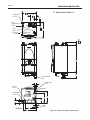
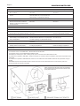
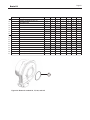
1.7 Dimensions, Brute LX
Figure 5. Dimensional Drawing, All Sizes

Page 5
Brute LX
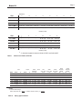
Table 1. Dimensional Tables, All Sizes
Table 2. Piping Type and Sizes
Dimension
Model
A B C D E F G H
J
*
K L M N O
50, 75 MBH
1" (3) 15-3/4" (40) 3-3/4" (9) 9-1/4" (24) 8" (20) 1-1/2" (4) 5-3/4" (14) 15-1/2" (39) -- -- -- 30-1/2" (78) 15-1/4"
(39)
4-5/8" (12)
100 MBH
1" (3) 15-1/2" (39) 1-1/4" (3) 12-3/4" (33) 11" (28) 1-1/4" (3) 9-1/2" (24) 14-3/4" (37) -- -- -- 30-1/2" (78) 18" (46) 4-5/8" (12)
125 MBH
1" (3) 15-1/2" (39) 1-1/4" (3) 12-3/4" (33) 11" (28) 1-1/4" (3) 9-1/2" (24) 14-3/4" (37) 2-3/4" (7) 12-3/4" (33) 2" (5) 30-1/2" (78) 18" (46) 4-5/8" (12)
150, 175 MBH
1-1/2" (4) 15-1/4" (39) 1-3/4" (4) 13" (33) 11-1/4" (28) 2-3/4" (7) 5-1/4" (14) 2" (5) 2-3/4" (7) 12-3/4" (33) 1-3/4" (5) 35-1/2" (90) 18" (46) 8-7/8" (23)
220 MBH
1-1/2" (4) 15-1/4" (39) 1-3/4" (4) 13" (33) 11-1/4" (28) 2-3/4" (7) 5-1/4" (14) 2" (5) -- -- -- 38-1/2" (90) 18" (46) 8-7/8" (23)
Dimension
Model
A B C D E F G H
J
*
K L M N O
50, 75 MBH
1" (3) 15-3/4" (40) 3-3/4" (9) 9-1/4" (24) 8" (20) 1-1/2" (4) 5-3/4" (14) 15-1/2" (39)
-- -- -- 30-1/2" (78) 15-1/4"
(39)
4-5/8" (12)
100 MBH
1" (3) 15-1/2" (39) 1-1/4" (3) 12-3/4" (33) 11" (28) 1-1/4" (3) 9-1/2" (24) 14-3/4" (37)
-- -- -- 30-1/2" (78) 18" (46) 4-5/8" (12)
125 MBH
1" (3) 15-1/2" (39) 1-1/4" (3) 12-3/4" (33) 11" (28) 1-1/4" (3) 9-1/2" (24) 14-3/4" (37)
2-3/4" (7) 12-3/4" (33) 2" (5) 30-1/2" (78) 18" (46) 4-5/8" (12)
150, 175 MBH
1-1/2" (4) 15-1/4" (39) 1-3/4" (4) 13" (33) 11-1/4" (28) 2-3/4" (7) 5-1/4" (14) 2" (5)
2-3/4" (7) 12-3/4" (33) 1-3/4" (5) 35-1/2" (90) 18" (46) 8-7/8" (23)
220 MBH
1-1/2" (4) 15-1/4" (39) 1-3/4" (4) 13" (33) 11-1/4" (28) 2-3/4" (7) 5-1/4" (14) 2" (5)
-- -- -- 38-1/2" (90) 18" (46) 8-7/8" (23)
*
-
J
dimension applies for both the DHW OUTLET and DHW INLET
inches (cm's)
inches (cm's)
Size
Size
APPLIANCE SUGGESTED SERVICE ACCESS CLEARANCE
SURFACE INCHES CM
Left Side 6 15
Right Side 6 15
Top 12 30
Closet, Front 6 15
Front 24 61
Bottom 24 61
Vent 1 3
Certi ed by CSA for zero clearance to
combustible materials on all sides.
APPLIANCE SUGGESTED SERVICE ACCESS CLEARANCE
SURFACE INCHES CM
Left Side 6 15
Right Side 6 15
Top 12 30
Closet, Front 6 15
Front 24 61
Vent 1 3
Certi ed by CSA for zero clearance to
combustible materials on all sides.
Clearances
Wall Floor
Sizing Data WALL
Sizing Data FLOOR STANDING
Sizing Data,
Piping
Input Output DHW AFUE Gas Water DHW Shipping
Model
Output @ Conn. Size Conn. Size Conn. Size Weight
BTU/h
kW BTU/h kW 75°F Rise inches inches inches lbs kg
MLX 50
50,000 14.6 47,500 13.2 - 95% 1/2” NPT 3/4” NPT - 88 40
MLX 75
75,000 21.9 71,250 20.8 - 95% 1/2” NPT 3/4” NPT - 97 44
MLX 100
100,000 29.3 95,000 27.8 - 95% 1/2” NPT 3/4” NPT - 112 51
MLX 125
125,000 36.6 118,750 34.8 3.1 gpm 95% 1/2” NPT 3/4” NPT 1/2” NPT 126 57
MLX 150
150,000 43.9 142,500 41.8 3.7 gpm 95% 1/2” NPT 1“ NPT 1/2” NPT 140 64
MLX 175
175,000 51.6 166,250 48.7 4.3 gpm 95% 1/2” NPT 1“ NPT 1/2” NPT 153 69
MLX 220
220,000 64.4 209,000 61.2 - 95% 1/2” NPT 1“ NPT - 161 73
Input Output DHW AFUE Gas Water DHW Shipping
Model Output @ Conn. Size Conn. Size Conn. Size Weight
BTU/h kW BTU/h kW 75°F Rise inches inches inches lbs kg
MLX 50 50,000 14.6 47,500 13.2 - 95% 1/2” NPT 3/4” NPT - 144 65
MLX 75 75,000 21.9 71,250 20.8 - 95% 1/2” NPT 3/4” NPT - 151 68
MLX 100 100,000 29.3 95,000 27.8 - 95% 1/2” NPT 3/4” NPT - 166 75
MLX 125 125,000 36.6 118,750 34.8 3.1 gpm 95% 1/2” NPT 3/4” NPT 1/2” NPT 178 81
MLX 150 150,000 43.9 142,500 41.8 3.7 gpm 95% 1/2” NPT 1“ NPT 1/2” NPT 184 83
MLX 175 175,000 51.6 166,250 48.7 4.3 gpm 95% 1/2” NPT 1“ NPT 1/2” NPT 192 87
MLX 220 220,000 64.4 209,000 61.2 - 95% 1/2” NPT 1“ NPT - 201 91
NOTES:
1. For other boiler ratings:
Boiler Horsepower: HP = Output Radiation Surface: EDR sq. ft. = Output
33,475 150
NOTES:
1. For other boiler ratings:
Boiler Horsepower: HP = Output Radiation Surface: EDR sq. ft. = Output
33,475 150
50 thru 125
150 - 220
Cond. Hydronic DHW 2nd Gas Hydronic DHW 2nd
Outlet Return Inlet Return Supply Supply Outlet Supply
3/4" 3/4" 1/2" 3/4" 1/2" 3/4" 1/2" 3/4"
PVC copper NPT copper NPT NPT NPT copper
3/4" 1" 1/2" 3/4" 1/2" 1" 1/2" 3/4"
PVC NPT NPT copper NPT NPT NPT copper
Shipping
Weight
lbs kg
- -
- -
- -
133 60
148 67
163 74
- -
Shipping
Weight
lbs kg
- -
- -
- -
188 85
194 88
202 92
- -
CombiBoiler
Size

Page 6
BRADFORD WHITE CORP
.
Figure 6. Contents of the Hardware Shipping Package
Some accessory items may be shipped in separate
packages. Verify receipt of all packages listed on the
packing slip. Inspect everything for damage immediately
upon delivery, and advise the carrier of any shortages
or damage. Any such claims must be led with the
carrier. The carrier, not the shipper, is responsible
for shortages and damage to the shipment whether
visible or concealed.
1.8 Unpacking
The Brute LX is shipped in a single crate with the
standard components packed with the appliance See
Figure 6:
1. Remove all packing and tie-down materials.
2. Check contents of the carton against items shown.
1) PRV
2) PRV Pipe w/ washer
3) Wall attach bracket
1
2
7
4
3
6
9
5
8
4) Outdoor sensor
5) Exhaust terminal assy
6) Air intake terminal assy
7) Gas Supply Shut Off Valve
8) Washer
9) Flow restrictor
1.9 Warranty
Bradford White Brute LX appliances are covered by
a limited warranty. The owner should complete the
warranty registration at www.bradfordwhite.com.
All warranty claims must be made to an authorized
Bradford White representative. Claims must include the
serial number and model (this information can be found
on the rating plate), installation date, and name of the
installer. Shipping costs are not included in the warranty
coverage.
Bird Screen

Page 7
Brute LX
SECTION 2.
Locating the Appliance
2.1 Locating the Appliance
The Brute LX is designed for indoor
wall-mounted installations only.
The Brute LX must be mounted to a suitable wall by a
qualied heating contractor under the guidelines of a
wall mounted boiler or combination unit. Use a suitable
wall, either concrete or wood and use the appropriate
fasteners for that wall. Failure to wall mount this boiler
using correct fasteners will affect the performance and
life expectancy of the boiler and will void the warranty.
The appliance should be located to provide clearances
on all sides for maintenance and inspection. It should
not be located in an area where leakage of any
connections will result in damage to the area adjacent to
the appliance, the wall that it is hung on, or to the lower
oors of the structure.
When such a location is not available, it is recommended
that a suitable drain pan, adequately drained, be installed
under the appliance.
The appliance is design certied by CSA-International
for wall-mounted installation in basements; in closets,
utility rooms or alcoves. The location for the appliance
should be chosen with regard to the vent pipe lengths
and external plumbing and on a plumb (vertical) wall.
The unit shall be installed such that the gas ignition
system components are protected from water (dripping,
spraying, rain, etc.) during operation and service
(circulator replacement, control replacement, etc.).
If the vent terminal and/or combustion air terminal
terminate through a wall, and there is potential for snow
accumulation in the local area, both terminals must
be installed at an appropriate level above grade or the
maximum expected snow line.
The dimensions and requirements that are shown in
Table 3 should be met when choosing the locations for
the appliance.
2.2 Correct Vent Distance from Outside
Wall or Roof Termination
The forced draft combustion air blower in the appliance
has sufcient power to vent properly when the
guidelines in Table 4 are followed.
For concentric vent terminal kit (optional), follow
installation instructions included with the kit.
NOTE: When located on the same wall, the Minimum
Venting Distance is found on Figure 11.
Figure 7. Locating the Appliance.
Table 3. Clearances
APPLIANCE SUGGESTED SERVICE ACCESS CLEARANCE
SURFACE INCHES CM
Left Side 6 15
Right Side 6 15
Top 12 30
Closet, Front 6 15
Front 24 61
Bottom 24 61
Vent 1 3
Certi ed by CSA for zero clearance to
combustible materials on all sides.
APPLIANCE SUGGESTED SERVICE ACCESS CLEARANCE
SURFACE INCHES CM
Left Side 6 15
Right Side 6 15
Top 12 30
Closet, Front 6 15
Front 24 61
Vent 1 3
Certi ed by CSA for zero clearance to
combustible materials on all sides.
Clearances
Wall Floor
Sizing Data WALL
Sizing Data FLOOR STANDING
Sizing Data,
Piping
Input Output DHW AFUE Gas Water DHW Shipping
Model Output @ Conn. Size Conn. Size Conn. Size Weight
BTU/h kW BTU/h kW 75°F Rise inches inches inches lbs kg
MLX 50 50,000 14.6 47,500 13.2 - 95% 1/2” NPT 3/4” NPT - 88 40
MLX 75 75,000 21.9 71,250 20.8 - 95% 1/2” NPT 3/4” NPT - 97 44
MLX 100 100,000 29.3 95,000 27.8 - 95% 1/2” NPT 3/4” NPT - 112 51
MLX 125 125,000 36.6 118,750 34.8 3.1 gpm 95% 1/2” NPT 3/4” NPT 1/2” NPT 126 57
MLX 150 150,000 43.9 142,500 41.8 3.7 gpm 95% 1/2” NPT 1“ NPT 1/2” NPT 140 64
MLX 175 175,000 51.6 166,250 48.7 4.3 gpm 95% 1/2” NPT 1“ NPT 1/2” NPT 153 69
MLX 220 220,000 64.4 209,000 61.2 - 95% 1/2” NPT 1“ NPT - 161 73
Input Output DHW AFUE Gas Water DHW Shipping
Model Output @ Conn. Size Conn. Size Conn. Size Weight
BTU/h kW BTU/h kW 75°F Rise inches inches inches lbs kg
MLX 50 50,000 14.6 47,500 13.2 - 95% 1/2” NPT 3/4” NPT - 144 65
MLX 75 75,000 21.9 71,250 20.8 - 95% 1/2” NPT 3/4” NPT - 151 68
MLX 100 100,000 29.3 95,000 27.8 - 95% 1/2” NPT 3/4” NPT - 166 75
MLX 125 125,000 36.6 118,750 34.8 3.1 gpm 95% 1/2” NPT 3/4” NPT 1/2” NPT 178 81
MLX 150 150,000 43.9 142,500 41.8 3.7 gpm 95% 1/2” NPT 1“ NPT 1/2” NPT 184 83
MLX 175 175,000 51.6 166,250 48.7 4.3 gpm 95% 1/2” NPT 1“ NPT 1/2” NPT 192 87
MLX 220 220,000 64.4 209,000 61.2 - 95% 1/2” NPT 1“ NPT - 201 91
NOTES:
1. For other boiler ratings:
Boiler Horsepower: HP = Output Radiation Surface: EDR sq. ft. = Output
33,475 150
NOTES:
1. For other boiler ratings:
Boiler Horsepower: HP = Output Radiation Surface: EDR sq. ft. = Output
33,475 150
50 thru 125
150 - 220
Cond. Hydronic DHW 2nd Gas Hydronic DHW 2nd
Outlet Return Inlet Return Supply Supply Outlet Supply
3/4" 3/4" 1/2" 3/4" 1/2" 3/4" 1/2" 3/4"
PVC copper NPT copper NPT NPT NPT copper
3/4" 1" 1/2" 3/4" 1/2" 1" 1/2" 3/4"
PVC NPT NPT copper NPT NPT NPT copper
Shipping
Weight
lbs kg
- -
- -
- -
133 60
148 67
163 74
- -
Shipping
Weight
lbs kg
- -
- -
- -
188 85
194 88
202 92
- -
CombiBoiler

Page 8
BRADFORD WHITE CORP
.
Figure 8. Mounting Detail.
Note: Brute LX
bracket and wall
bracket are
purposely offset.
Bracket factory-
mounted
on back of Mascot
Wall bracket
provided by
Bradford White
Wall to which Brute
LX is mounted
Anchor / fastener provided
by Installer - appropriate for
250 lbs (114 kg) operating
weight
Figure 9. Wall Bracket Hole Mounting Locations
B 366 0
A 4-1/2 11.5
B 29- 3/4 75.7
A 5-
B 33-6 85.2
A 54 14.7
DIMENSIONS
MASCOT LX
MODEL SIZE
DESIGNATOR INCHES CM
50, 75, 100, 125
150/175
220
SH
1
MANUAL, MASCOT LX
H23686
D
C
B
A
B
C
D
1
2
H23686
THIRD ANGLE PROJECTION.
PROPRIETARY TO LAARS HEATING SYSTEMS AND SHALL NOT BE
1/8"
WAS 1:1 SCALE WALL TEMPLATE, NOW GRAPHICS FOR
3
4
4
APPR
2
BY LAARS HEATING SYSTEMS.
FMA56A
.1
DECIMALS .XX
3
1
REV
A
CD 5-12-14
REVISIONS
REV.
CHANGE:
CD 4-24-14
TOLERANCES ARE:
FINISH
NONE
PURPOSE EXCEPT AS SPECIFICALLY AUTHORIZED IN WRITING
USE IN I/O MANUAL
A
14-034N JM 5-12-14
DECIMALS .X
INTENDED SIZE:
SOFTWARE DWG. NO:
C
SHEET 1 OF 1
REV.
DWG NO.
.03
DECIMALS .XXX
TITLE:
REPRODUCED, TRANSFERRED TO OTHER DOCUMENTS, USED OR
.010
SCALE: NONE
MATERIAL:
DISCLOSED TO OTHERS FOR MANUFACTURING OR ANY OTHER
DIMENSIONS ARE IN INCHES.
APPROVALS
ENGR APPR
ECN
NONE
DRAFT
ENGR
DRAFT
JM 4-24-14
S
CHECK
APPR
UNLESS OTHERWISE SPECIFIED:
DO NOT SCALE DRAWING.
THIS DOCUMENT AND THE INFORMATION CONTAINED HEREIN ARE
ANGLES
FRACTIONS
WALL TEMPLATE, I/O
A
Safety Wall Bracket, Qty 2
(supplied)
12P4010
Dimensions shown in Inches and centimeters
3
4
8.1 cm
40.6 cm
16”
A
Concentric
"
1
43.2 cm
17
"
B
Overall Width
2" Exhaust and
2" Air Inlet
19.6 cm
7
3
4
"
Bolts/Anchors (4)
provided by installer,
each is to be suitable for
160 lbs [73kg]
minimum.
Centered
Wall Bracket
(supplied)
12P3013
Wall Mounting Dimensions
Zero clearance to combustables allowed
Recommended service clearances:
Sides: 3" / 15cm
Top 6" / 15cm
Bottom: 24" / 61cm
Front: 24" / 61cm
11.5
75.6
13.4
85.2
14.6
93.0
B
A
Desired top of Brute LX
B 366 0
A 4-1/2
11.5
B 29- 3/4
75.7
A 5-
B 33-6 85.
2
A 54
14.7
DIMENSIONS
MASCOT LX
MODEL SIZE
DESIGNATOR INCHES CM
50, 75, 100, 125
150/175
220
SH
1
MANUAL, MASCOT LX
H23686
D
C
B
A
B
C
D
1
2
H23686
THIRD ANGLE PROJECTION.
PROPRIETARY TO LAARS HEATING SYSTEMS AND SHALL NOT BE
1/8"
WAS 1:1 SCALE WALL TEMPLATE, NOW GRAPHICS FOR
3
4
4
APPR
2
BY LAARS HEATING SYSTEMS.
FMA56A
.1
DECIMALS .XX
3
1
REV
A
CD 5-12-14
REVISIONS
REV.
CHANGE:
CD 4-24-14
TOLERANCES ARE:
FINISH
NONE
PURPOSE EXCEPT AS SPECIFICALLY AUTHORIZED IN WRITING
USE IN I/O MANUAL
A
14-034N JM 5-12-14
DECIMALS .X
INTENDED SIZE:
SOFTWARE DWG. NO:
C
SHEET 1 OF 1
REV.
DWG NO.
.03
DECIMALS .XXX
TITLE:
REPRODUCED, TRANSFERRED TO OTHER DOCUMENTS, USED OR
.010
SCALE: NONE
MATERIAL:
DISCLOSED TO OTHERS FOR MANUFACTURING OR ANY OTHER
DIMENSIONS ARE IN INCHES.
APPROVALS
ENGR APPR
ECN
NONE
DRAFT
ENGR
DRAFT
JM 4-24-14
S
CHECK
APPR
UNLESS OTHERWISE SPECIFIED:
DO NOT SCALE DRAWING.
THIS DOCUMENT AND THE INFORMATION CONTAINED HEREIN ARE
ANGLES
FRACTIONS
WALL TEMPLATE, I/O
A
Safety Wall Bracket, Qty 2
(supplied)
12P4010
Dimensions shown in Inches and centimeters
3
4
8.1 cm
40.6 cm
16”
A
Concentric
"
1
43.2 cm
17
"
B
Overall Width
2" Exhaust and
2" Air Inlet
19.6 cm
7
3
4
"
Bolts/Anchors (4)
provided by installer,
each is to be suitable for
160 lbs [73kg]
minimum.
Centered
Wall Bracket
(supplied)
12P3013
Wall Mounting Dimensions
Zero clearance to combustables allowed
Recommended service clearances:
Sides: 3" / 15cm
Top 6" / 15cm
Bottom: 24" / 61cm
Front: 24" / 61cm
11.5
75.6
13.4
85.2
14.6
93.0
2.2 Wall Mount Hole Locations.
5-1/4
33-1/2
5-3/4
36-1/2

Page 9
Brute LX
Table 4. Vent / Air Pipe Sizes
Vent System
Vent System
INTAKE / EXHAUST
Max Equivalent
*
Vent and Air Pipe Length (each)
STANDARD OPTIONAL
Size 2" dia 5.1cm 3"/5" dia 7.6/12.7cm
125 40 ft 12.2m 40 ft 12.2m
Installations in the U.S. require exhaust vent pipe that is PVC or CPVC complying
with ANSI/ASTM D1785 F441 or stainless steel complying with UL1738. Laars
supplies the rst section of vent pipe which is 16" of CPVC with each boiler. Installa-
tions in Canada require exhaust vent pipe that is certi ed to ULC S636.
Intake (air) pipe may be PVC, CPVC, ABS or galvanized pipe.
*
To calculate equivalent length, measure the linear feet of the pipe, and add 5 feet
(1.5m) for each elbow used.
INTAKE AND EXHAUST LENGTH
MAX EQUIV. MAX EQUIV. CONCENTRIC MAX EQUIV.
SIZE VENT FT. M VENT FT. M VENT FT. M
50 2" 40 6.1 *3"* 150 30.5 3/5" 40 6.1
75 2" 40 6.1 *3"* 150 30.5 3/5" 40 6.1
100 2" 40 6.1 *3"* 150 30.5 3/5" 40 6.1
125 2" 40 6.1 *3"* 150 30.5 3/5" 40 6.1
150 2" 40 6.1 *3"* 150 30.5 3/5" 40 6.1
175 2" 40 6.1 *3"* 150 30.5 3/5" 40 6.1
220 2" 30 4.6 *3"* 120 24.4 3/5" 40 6.1
INTAKE / EXHAUST
Max Equivalent Vent and Air Pipe Length (each)
STANDARD 2-PIPE STANDARD 2-PIPE OPTIONAL CONCENTRIC
SIZES DIA. F T. m DIA. FT. m DIA. F T. m
50 - 175 2" 40 12.2 *3"* 150 45.7 3/5" 40 12.2
220 2” 30 9.1 *3”* 120 36.6 3/5” 40 12.2
Installations in the U.S. require exhaust vent pipe that is a combination of PVC & CPVC complying with
ANSI/ASTM D1785 F441 or stainless steel complying with UL1738. Polypropylene installations require
exhaust vent pipe that is certi ed to ULC S636.
Intake (air) pipe may be any material that complies with ANSI/ASTM D1785 F441, ABS that complies with
ANSI/ASTM D1527 or galvanized material.
Installer must comply fully with manufacturer's installation instructions, to maintain ANSI Z21.13 safety
certi cation.
Closet and alcove installations do not allow the use of PVC under any circumstances
To calculate max equivalent length, measure the linear feet of the pipe, and add 5 feet (1.5m) for each
elbow used.
* Must use 2x3 adapter within 1 ft. (30cm) of boiler.
Electrical
Data
Size Boiler
Volts Phase Amps
MLX 50 120 Single 1.5
MLX 75 120 Single 1.5
MLX 100 120 Single 1.5
MLX 125 120 Single 1.5
MLX 150 120 Single 1.5
MLX 175 120 Single 2.2
MLX 220 120 Single 2.2
*
Minimum 15A circuit required
* Must use 2x3 adapter within 1 ft. (30cm) of boiler.
Reference the Installation and Operation Manual for more details.
SECTION 3.
Venting and Combustion Air
The Brute LX includes a standard CPVC vent/combustion
air adapter. If eld connections require use of PVC/CPVC
vent materials, the installer must use proper adhesive to
join CPVC and/or PVC pipe and ttings.
3.1 Combustion Air
Brute LX boilers and water heaters must have provisions
for combustion and ventilation air in accordance with the
applicable requirements for Combustion Air Supply and
Ventilation in the National Fuel Gas Code, ANSI Z223
1; or in Canada, the Natural Gas and Propane Installation
Code, CSA B149.1. All applicable provisions of local
building codes must also be adhered to.
A Brute LX unit can take combustion air from the
space in which it is installed, or the combustion air
can be ducted directly to the unit. Ventilation air must
be provided in either case.
3.1.1 Combustion Air from Room
In the United States, the most common requirements
specify that the space shall communicate with the
outdoors in accordance with method 1 or 2, which follow.
Where ducts are used, they shall be of the same cross-
sectional area as the free area of the openings to which
they connect.
Method 1: Two permanent openings, one commencing
within 12" (300mm) of the top and one commencing
within 12" (300mm) of the bottom, of the enclosure
shall be provided. The openings shall communicate
directly, or by ducts, with the outdoors or spaces
that freely communicate with the outdoors. When
directly communicating with the outdoors, or when
communicating to the outdoors through vertical ducts,
each opening shall have a minimum free area of 1
square inch per 4000 Btu/hr (550 square mm/kW) of
total input rating of all equipment in the enclosure.
When communicating to the outdoors through
horizontal ducts, each opening shall have a minimum
free area of not less than 1 square inch per 2000 Btu/
hr (1100 square mm/kW) of total input rating of all
equipment in the enclosure.
Method 2: One permanent opening, commencing
within 12" (300mm) of the top of the enclosure, shall
be permitted. The opening shall directly communicate
with the outdoors or shall communicate through a
vertical or horizontal duct to the outdoors or spaces
that directly communicate with the outdoors and shall
have a minimum free area of 1 square inch per 3000

Page 10
BRADFORD WHITE CORP
.
The ue temperature of the Brute LX changes
dramatically with changes in operating water
temperature. Therefore, it is necessary to assess the
application of the boiler to determine the required
certied vent class. If the Brute LX is installed in
an application where the ambient temperature is
elevated, and/or installed in a closet/alcove, CPVC,
polypropylene, or stainless steel material is required.
If the system temperatures are unknown at the time
of installation, stainless, polypropylene or CPVC
material is recommended.
The Brute LX is a Category IV appliance and may
be installed with PVC, CPVC or polypropylene that
complies with ULC-S636, ANSI/ASTM D1785 F441
(see Table 4) or a stainless steel venting system that
complies with UL 1738 Standard (see Table 8).
WARNING
Failure to use the appropriate vent material, installation
techniques, glues/sealants could lead to vent failure
causing property damage, personal injury or death.
WARNING
Btu/hr (734 square mm/kW) of the total input rating of
all equipment located in the enclosure. This opening
must not be less than the sum of the areas of all vent
connectors in the conned space.
Other methods of introducing combustion and
ventilation air are acceptable, providing they conform to
the requirements in the applicable codes listed above.
In Canada, consult local building and safety codes or, in
absence of such requirements, follow CAN/CGA B149.
3.1.2 Ducted Combustion Air
The combustion air can be taken through the wall, or
through the roof. When taken from the wall, it must be
taken from out-of-doors by means of the Bradford White
horizontal wall terminal, shown in Table 5. See Table 4
to select the appropriate diameter air pipe. When taken
from the roof, a eld-supplied rain cap or an elbow
arrangement must be used to prevent entry of rain water
(see Figure 5).
Use ABS, PVC, CPVC, polypropylene, or galvanized
pipe for the combustion air intake (see Table 6), sized
per Table 4. Route the intake to the boiler as directly
as possible. Seal all joints. Provide adequate hangers.
The unit must not support the weight of the combustion
air intake pipe. Maximum linear pipe length allowed is
shown in Table 4. Subtract 5 allowable linear ft. (1.5m)
for every elbow used.
The connection for the intake air pipe is at the top of the
unit (see Figure 3).
In addition to air needed for combustion, air shall also
be supplied for ventilation, including air required for
comfort and proper working conditions for personnel.
3.2 Venting (Exhaust)
Table 5. Vent Termination Options
Part Number Size Description
239-44069-02 2" PVC Concentric Vent Terminal
239-44069-01 3" PVC Concentric Vent Terminal
CA010101 2" Flush Vent Terminal PVC
CA010100 3" Flush Vent Terminal PVC
CA007100 3" to 5" Stainless Steel Concentric Vent Terminal
INSTALLATION STANDARDS
MATERIAL UNITED STATES CANADA
ABS ANSI/ASTM D1527
PVC, sch 40 ANSI/ASTM D1785 or D2665 Air pipe material must be chosen
CPVC, sch 40 ANSI/ASTM F441 CPVC, sch 40, ANSI/ASTM, Polypropylene
Polypropylene UL1738, ULC S636. based upon the intended application of the boiler.
Single wall galv. steel 26 gauge
Table 6. Required Combustion Air Pipe Material.

Page 11
Brute LX
NOTICE
For Category II and IV boilers, be installed so as to
prevent accumulation of condensate; and
For Category II and IV boilers, where necessary,
have means provided for drainage of condensate.
AVIS
les chaudières de catégories II et IV doivent être
installées de façon à empêcher l'accumulation de
condensat; et
si nécessaire, les chaudières de catégories II et IV
doivent être pourvues de dispositifs d'évacuation du
condensat.
NOTICE
The instructions for the installation of the venting
system shall specify that the horizontal portions of
the venting system shall be supported to prevent
sagging; the methods of and intervals for support
shall be specied. These instructions shall also
specify that the venting system:
Category I, II and IV boilers must be installed so
that horizontal sections have a slope of at least ¼
inch per foot (21 mm/m) to prevent accumulation of
condensate; and
For Category II and IV boilers, where necessary,
have means provided for drainage of condensate.
AVIS
Les instructions d'installation du système
d'évacuation doivent préciser que les sections
horizontales doivent être supportées pour prévenir
le échissement. Les méthodes et les intervalles
de support doivent être spéciés. Les instructions
doivent aussi indiquer les renseignements suivants:
les chaudières de catégories I, II et IV doivent
présenter des tronçons horizontaux dont la pente
montante est d'au moins ¼ po par pied (21 mm/m)
entre la chaudière et l'évent; les chaudières de
catégories II et IV doivent être installées de façon à
empêcher l'accumulation de condensat;
et si nécessaire, les chaudières de catégories II et IV
doivent être pourvues de dispositifs d'évacuation du
condensat.
All venting must be installed according to this manual
and any other applicable local codes, including but
not limited to, ANSI Z223.1/NFPA 54, CSA B149.1,
CSAB149.2 and ULC-S636. Failure to follow this
manual and applicable codes may lead to property
damage, severe injury, or death.
INSTALLATIONS IN CANADA require the use
of venting material certied to ULCS636. All Gas
vents connected to the Brute LX, plastic, stainless
steel or otherwise must be certied to this ULC
standard. Appropriate selection of vent material is
very important for proper performance and safe
operation of the Brute LX.
The ue temperature of the Brute LX changes
dramatically with changes in operating water
temperature. Therefore, it is necessary to assess the
application of the boiler to determine the required
certied vent class. If the Brute LX is installed in
an application where the outlet water temperature
exceeds 145°F, and/or installed in a closet, class
IIB or higher vent material is required. If the
system temperatures are unknown at the time of
installation, class IIB or higher venting material is
recommended.
IN CANADA all venting used must meet the
following requirements:
1. ULC-S636 certied and marked
2. The rst 3 feet of venting must be accessible for
visual inspection.
3. All components used in the vent system must be
from a certied manufacturer.
4 . Vent system components must not be mixed
with alternate manufacturers certied
components and/or unlisted components.
5 . The venting must be installed according to the
vent manufacturers installation instructions.
The unit’s vent can terminate through the roof, or
through an outside wall.
See Table 4 to select the appropriate vent pipe
diameter. Vent pipe must pitch upward, toward the vent
terminal, not less than 1/4" per foot, so that condensate
will run back to the Brute LX to drain. Route vent pipe
to the heater as directly as possible. Seal all joints and
provide adequate hangers as required in the venting
system manufacturer’s Installation Instructions.
Horizontal portions of the venting system must be
supported to prevent sagging and may not have any
low sections that could trap condensate. The unit must
not support the weight of the vent pipe.

Page 12
BRADFORD WHITE CORP
.
Figure 10. Minimum Venting Distance.
NOTICE
DO NOT COMMON VENT BRUTE LX UNITS.Brute
LX units are never permitted to share a vent with
Category I appliances.
AVIS
NE PAS ÉVENT COMMUNE BRUTE LX UNITÉS.
Brute LX unités ne sont jamais autorisés à
partager un évent Catégorie I avec les appareils.
3.2.1 About Common Venting
Table 7. Allowable Vent Manufacturers
INSTALLATION STANDARDS
MATERIAL UNITED STATES CANADA
Stainless Steel UL 1738 Venting must be ULC-S636 certied for use as
PVC, sch 40 ANSI/ASTM D178
venting material. The venting material must be chosen
CPVC, sch 40 ANSI/ASTM F441 based upon the intended application of the boiler.
Polypropylene UL1738 or ULC-S636
Table 8. Required Exhaust Vent Material.
Allowable Polypropylene Vent Manufacturers
/ Trade Names
MFR (model number abbreviated*)
Centrotherm DuraVent Selkirk
InnoFlue PolyPro Polyflue
Single Wall Pipe ISVLxxxx xPPS-x xPF-xx
Elbow ESELxxxx xPPS-E90 xPF-90
PVC adapter ISAGxxxx xPPS-AD xPF-PVC-PF
Notes:
Only the above manufacturers and models have been approved.
Substitutes are not allowed.
Trade Names/Models
"x", "xx" and "xxxx" refer to variations in nominal size. See manufacturer's
catalog for a particular application.
These manufacturers samples have been tested and authorized to safely
operate with Laars equpment.
Contact Polypropylene manufacturer's distributor for complete model
number selection.
Installer must follow Polypropylene manufacturers installation instructions.
Example
Components
Manufacturers materials and models may not be mixed in the same
application.
These manufacturers samples have been tested and authorized to safely
operate with Bradford White equipment

Page 13
Brute LX
Figure 11. Combustion Air and Vent Through Roof.
issues.
3.3.2 Side Wall Combustion Air Terminal
The Bradford White side wall combustion air terminal,
or concentric terminal (see Table 5), must be used
when the heater takes air from a side wall. Consider the
following when installing the terminal (see Figure 12):
1. Do not locate the air inlet terminal near a source
of corrosive chemical fumes (e.g., cleaning uid,
chlorine compounds, etc.)
2. Locate the terminal so that it will not be subject to
damage by accident or vandalism. It must be at least
7 feet (2.1m) above a public walkway.
3. Locate the combustion air terminal so that it cannot
be blocked by snow. The National Fuel Gas Code
requires that it be at least 12 inches (30cm) above
grade, but the installer may determine it should be
higher, depending upon local conditions.
4. For concentric vent, follow instructions included
with vent kit.
5. Multiple vent kits should be installed such that the
horizontal distance between outlet group and inlet
group is 36" (90cm) minimum.
6. Vent outlet must be no lower than the center of the
air inlet, and must be at least 12" (30cm) away from
the air inlet (see Figure 10).
3.3 Locating Vent & Combustion Air
Terminals
3.3.1 Side Wall Vent Terminal
The appropriate Bradford White side wall vent
terminal must be used. The terminal must be located in
accordance with ANSI Z223.1/NFPA 54 and applicable
local codes. In Canada, the installation must be in
accordance with CSA B149.1 or .2 and local applicable
codes. Consider the following when installing the
terminal:
1. Figure 12 shows the requirements for mechanical
vent terminal clearances for the U.S. and Canada.
2. Vent terminals for condensing appliances or
appliances with condensing vents are not permitted
to terminate above a public walkway, or over an
area where condensate or vapor could create a
nuisance or hazard.
3. Locate the vent terminal so that vent gases cannot
be drawn into air conditioning system inlets.
4. Locate the vent terminal so that vent gases cannot
enter the building through doors, windows, gravity
inlets or other openings. Whenever possible, avoid
locations under windows or near doors.
5. Locate the vent terminal so that it cannot be
blocked by snow. The installer may determine
that a vent terminal must be higher than the
minimum shown in codes, depending upon local
conditions.
6. Locate the terminal so the vent exhaust does not
settle on building surfaces or other nearby objects.
Vent products may damage surfaces or objects.
7. If the boiler or water heater uses ducted combustion
air from an intake terminal located on the same
wall, see Figure 12 for proper spacing and
orientation.
If the vent termination is located in an area exposed to
high winds, an optional PVC tee (the same diameter as
the vent pipe) may be used. The tee'd vent termination
offers greater protection from wind related operating

Page 14
BRADFORD WHITE CORP
.
*When vent terminal is less than 10 feet (3m) horizontally
from a forced air inlet, the terminal must be at least 3 feet
(0.9m) above the air inlet.
Figure 12. Combustion Air and Vent Through Side Wall.
U.S. Installations (see note 1) Canadian Installations (see note 2)
A= Clearance above grade, veranda, porch, 12 inches (30 cm) 12 inches (30 cm)
deck, or balcony See note 6 See note 6
B= Clearance to window or door that may be Direct vent only: 12 inches (30cm); 36 inches (91 cm)
opened Other than Direct vent: 4 ft (1.2m) below or to
side of opening; 1 ft (30cm) above opening
C= Clearance to permanently closed window See note 4 See note 5
D= Vertical clearance to ventilated soft located
above the terminal within a horizontal See note 4 See note 5
distance of 2 feet (61cm) from the center
line of the terminal
E= Clearance to unventilated soft See note 4 See note 5
F= Clearance to outside corner See note 4 See note 5
G= Clearance to inside corner 3 feet (91 cm) minimum See note 5
H= Clearance to each side of center line 3 feet (91 cm) within a height 15 feet
extended above meter/regulator assembly See note 4 above the meter/regulator assembly
I= Clearance to service regulator vent outlet See note 4 3 feet (91 cm)
J= Clearance to nonmechanical air supply Direct vent only: 12" (30cm) 80-285; 36" (91cm)
inlet to building or the combustion air inlet 399-850. Other than Direct vent: 4 ft (1.2m) below 36 inches (91 cm)
to any other appliance or to side of opening; 1 ft (30cm) above opening
K= Clearance to a mechanical air supply inlet 3 feet (91 cm) above if within 10 feet (3 m) 6 feet (1.83 m)
horizontally
L= Clearance above paved sidewalk or paved Vent termination not allowed in this location Vent termination not allowed in this
driveway located on public property for category IV appliances. location for category IV appliances.
M= Clearance under veranda, porch, deck, See note 4 12 inches (30 cm) (see note 3)
or balcony
Notes:
1. In accordance with the current ANSI Z223.1 / NFPA 54 National Fuel Gas Code.
2. In accordance with the current CAN/CGA-B149 Installation Codes.
3. Permitted only if veranda, porch, deck, or balcony is fully open on a minimum of two sides beneath the oor.
4. For clearances not specied in ANSI Z223.1 / NFPA 54, clearance is in accordance with local installation codes and the requirements of the
gas supplier.
5. For clearances not specied in CAN/CGA-B149, clearance is in accordance with local installation codes and the requirements of the gas
supplier.
6. IMPORTANT: terminal must be placed such that it remains a minimum 12" above expected snow line. Local codes may have more
specic requirements, and must be consulted.

Page 15
Brute LX
3.3.3 Vertical Vent Terminal
When the unit is vented through the roof, the vent must
extend at least 3 feet (0.9m) above the point at which it
penetrates the roof. It must extend at least 2 feet (0.6m)
higher than any portion of a building within a horizontal
distance of 10 feet (3.0m), and high enough above the
roof line to prevent blockage from snow. When the
combustion air is taken from the roof, the combustion
air must terminate at least 12" (30cm) below the vent
terminal (see Figure 11).
3.3.4 Vertical Combustion Air Terminal
When combustion air is taken from the roof, a eld-
supplied rain cap or an elbow arrangement must be
used to prevent entry of rain water (see Figure 11). The
opening on the end of the terminal must be at least 12"
(30cm) above the point at which it penetrates the roof,
and high enough above the roof line to prevent blockage
from snow. When the vent terminates on the roof, the
combustion air must terminate at least 12" (30cm) below
the vent terminal.
3.3.5 Installations in the Commonwealth of
Massachusetts
In Massachusetts the following items are required if the
side-wall exhaust vent termination is less than seven
(7) feet above nished grade in the area of the venting,
including but not limited to decks and porches. From
Massachusetts Rules and regulations 248 CMR 5.08
1. Installation of Carbon Monoxide Detectors
At the time of installation of the side wall vented
gas fueled appliance, the installing plumber or gastter
shall observe that a hard-wired carbon monoxide
detector with an alarm battery back-up is installed on the
oor level where the gas appliance is to be installed. In
addition, the installing plumber or gastter shall observe
that a battery operated or hard-wired carbon monoxide
detector with an alarm is installed on each additional
level of the dwelling, building or structure served by
the side-wall horizontally vented gas fueled equipment.
It shall be the responsibility of the property owner to
secure the services of qualied licensed professionals for
installation of hard-wired carbon monoxide detectors.
a. In the event that the side-wall horizontally
vented gas fueled equipment is installed in a crawl
space or an attic, the hard-wired carbon monoxide with
alarm and battery back-up may be installed on the next
adjacent oor level.
b. In the event that the requirements of the
subdivision cannot be met at the time of completion of
installation, the owner shall have a period of thirty (30)
days to comply with the above requirements, provided,
however, that during said thirty (30) day period, a
battery operated carbon monoxide detector with an
alarm be installed.
2. Approved Carbon Monoxide Detectors
Each carbon monoxide detector shall comply
with NFPA 720 and be ANSI/UL 2034 listed and IAS
certied.
3. Signage. A metal or plastic identication plate
shall be permanently mounted to the exterior of the
building at a minimum height of eight (8) feet above
grade directly in line with the exhaust vent terminal
for horizontally vented gas fueled heating appliance
or equipment. The sign shall read, in print no less than
one-half (1/2) inch in size: "GAS VENT DIRECTLY
BELOW, KEEP CLEAR OF ALL OBSTRUCTIONS".
4. Inspection
The state or local gas inspector of the side-wall
horizontally vented gas fueled appliance shall not
approve the installation unless, upon inspection, the
inspector observes carbon monoxide detectors and
signage installed in accordance with the provisions of
248 CMR 5.08(2)(a) 1-4.

Page 16
BRADFORD WHITE CORP
.
NOTICE
At the time of removal of an existing boiler, the following
steps shall be followed with each appliance remaining
connected to the common venting system placed
in operation, while the other appliances remaining
connected to the common venting system are not in
operation.
1. Seal any unused openings in the common venting
system.
2. Visually inspect the venting system for proper size and
horizontal pitch and determine there is no blockage or
restriction, leakage, corrosion and other deciencies
which could cause an unsafe condition.
3. Insofar as is practical, close all building doors and
windows and all doors between the space in which
the appliances remaining connected to the common
venting system are located and other spaces of the
building. Turn on clothes dryers and any appliance not
connected to the common venting system. Turn on
any exhaust fans, such as range hoods and bathroom
exhausts, so they will operate at maximum speed.
4. Place in operation the appliance being inspected.
Follow the lighting instructions. Adjust thermostat so
the appliance will operate continuously.
5. Operate the main burner for 5 minutes then,
determine if the cut-draw overows to the discharge
opening. Use the ame of a match or a candle or the
smoke of a cigarette, a cigar or a pipe
6. Once it has been determined, according to the
method indicated above, that each device connected
to the drainage system is placed in the open air in
an adequate manner. Install the doors and windows,
fans, the registers of chimneys and gas appliances to
their original position
7. Tout mauvais fonctionnement du système d'évacuation
commun devrait être corrigé de façon que l'installation
soit conforme au National Fuel Gas Code, ANSI
Z223.1/NFPA 54 et (ou) aux codes d'installation CAN/
CSA-B149.1. Si la grosseur d'une section du système
d'évacuation doit être modiée, le système devrait
être modié pour respecter les valeurs minimales des
tableaux pertinents de l'appendice F du National Fuel
Gas Code, ANSI Z223.1/NFPA 54 et (ou) les codes
d'installation CAN/CSA-B149.1
AVIS
Au moment du retrait d'une chaudière existante, les
mesures suivantes doivent être prises pour chaque
appareil toujours raccordé au système d'évacuation
commun et qui fonctionne alors que d'autres appareils
toujours raccordés au système d'évacuation ne
fonctionnent pas:
1. Sceller toutes les ouvertures non utilisées du système
d'évacuation.
2. Inspecter de façon visuelle le système d'évacuation
pour déterminer la grosseur et l'inclinaison horizontale
qui conviennent et s'assurer que le système est
exempt d'obstruction, d'étranglement, de fuite,
de corrosion et autres défaillances qui pourraient
présenter des risques.
3. Dans la mesure du possible, fermer toutes les
portes et les fenêtres du bâtiment et toutes les
portes entre l'espace où les appareils toujours
raccordés au système d'évacuation sont installés et
les autres espaces du bâtiment. Mettre en marche
les sécheuses, tous les appareils non raccordés au
système d'évacuation commun et tous les ventilateurs
d'extraction comme les hottes de cuisinière et les
ventilateurs des salles de bain. S'assurer que ces
ventilateurs fonctionnent à la vitesse maximale. Ne
pas faire fonctionner les ventilateurs d'été. Fermer les
registres des cheminées.
4. Mettre l'appareil inspecté en marche. Suivre les
instructions d'allumage. Régler le thermostat de façon
que l'appareil fonctionne de façon continue.
5. Faire fonctionner le brûleur principal pendant 5 min
ensuite, déterminer si le coupe-tirage déborde à
l'ouverture de décharge. Utiliser la amme d'une
allumette ou d'une chandelle ou la fumée d'une
cigarette, d'un cigare ou d'une pipe.
6. Une fois qu'il a été déterminé, selon la méthode
indiquée ci-dessus, que chaque appareil raccordé
au système d'évacuation est mis à l'air libre de
façon adéquate. Remettre les portes et les fenêtres,
les ventilateurs, les registres de cheminées et les
appareils au gaz à leur position originale.
7. Tout mauvais fonctionnement du système d'évacuation
commun devrait être corrigé de façon que l'installation
soit conforme au National Fuel Gas Code, ANSI
Z223.1/NFPA 54 et (ou) aux codes d'installation CAN/
CSA-B149.1. Si la grosseur d'une section du système
d'évacuation doit être modiée, le système devrait
être modié pour respecter les valeurs minimales des
tableaux pertinents de l'appendice F du National Fuel
Gas Code, ANSI Z223.1/NFPA 54 et (ou) les codes
d'installation CAN/CSA-B149.1
3.4 Common Vent Test
NOTE: This section does not describe a method for
common venting Brute LX units. It describes what
must be done when an existing unit is removed from a
common vent system.
Brute LX units require special vent systems and fans for
common vent. See Section 3.2.1 or contact the factory
if you have questions about common venting Brute LX
units.
Page is loading ...
Page is loading ...
Page is loading ...
Page is loading ...
Page is loading ...
Page is loading ...
Page is loading ...
Page is loading ...
Page is loading ...
Page is loading ...
Page is loading ...
Page is loading ...
Page is loading ...
Page is loading ...
Page is loading ...
Page is loading ...
Page is loading ...
Page is loading ...
Page is loading ...
Page is loading ...
Page is loading ...
Page is loading ...
Page is loading ...
Page is loading ...
Page is loading ...
Page is loading ...
Page is loading ...
Page is loading ...
Page is loading ...
Page is loading ...
Page is loading ...
Page is loading ...
Page is loading ...
Page is loading ...
Page is loading ...
Page is loading ...
-
 1
1
-
 2
2
-
 3
3
-
 4
4
-
 5
5
-
 6
6
-
 7
7
-
 8
8
-
 9
9
-
 10
10
-
 11
11
-
 12
12
-
 13
13
-
 14
14
-
 15
15
-
 16
16
-
 17
17
-
 18
18
-
 19
19
-
 20
20
-
 21
21
-
 22
22
-
 23
23
-
 24
24
-
 25
25
-
 26
26
-
 27
27
-
 28
28
-
 29
29
-
 30
30
-
 31
31
-
 32
32
-
 33
33
-
 34
34
-
 35
35
-
 36
36
-
 37
37
-
 38
38
-
 39
39
-
 40
40
-
 41
41
-
 42
42
-
 43
43
-
 44
44
-
 45
45
-
 46
46
-
 47
47
-
 48
48
-
 49
49
-
 50
50
-
 51
51
-
 52
52
-
 53
53
-
 54
54
-
 55
55
-
 56
56


Ask a question and I''ll find the answer in the document
Finding information in a document is now easier with AI
Related papers
-
Bradford White BFTCF-199 User manual
-
Bradford White BMFTCW-199 User manual
-
-
-
-
-
-
-
-
Bradford White BNTH-600 User manual
Other documents
-
Dunkirk Q95M-200 Modulating Condensing Boiler Installation & Operation Manual
-
-
-
Dunkirk Q90-200 Series II Installation & Operation Manual
-
-
Bryant BWH Owner's manual
-
Laars MASCOT LX User manual
-
State SCB-110S-N , SCB-110H-N , SCB-110S-P , SCB-110H-P , SCB-150S-N , SCB-150H-N , SCB-150S-P , SCB-150H-P , SCB-199S-N , SCB-199H-N , SCB-199S-P , SCB-199H-P User manual
-
-
FTHW Wall-Mounted Gas Condensing Heating Only Boiler User manual