Page is loading ...

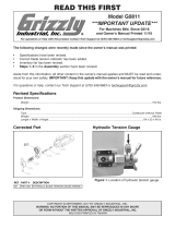
Listed below are the components of the dial
protractor. Match the description with the
corresponding part number in the illustration
to the right. Becoming familiar with these
terms will aid in comprehension of the
instructions.
1. The Dial Numbers represent whole
degrees. Each line indicates 5 min-
utes of a degree or
1
⁄12 of a degree.
2. The Needle Indicator points to the
degree mark.
3. The Rotation Lock secures the dial.
This is used to maintain the angle,
once the angle is set.
4. The Blade Lock secures the blade
to the dial plate. Loosening allows
removal and adjustment along its
length.
5. The Decade Counter indicates
every 10˚.
6. The Protractor Body is the main
structure in the protractor.
7. The Beam is the reference surface of
the protractor body.
© 2001 Grizzly Industrial, Inc.344501622
The G9900 Dial Protractor features 5 minute resolution, a 1
1
⁄2" easy-to-read dial, acute angle attachment
and precision ground stainless steel construction. Using this tool will allow you to measure angles or set
up angular dimensions quickly and precisely.
Please read the instructions below to maximize the effectiveness of this tool. If you need additional assis-
tance with any of these instructions, please contact our Customer Service Department at 570-546-9663 or
by internet at [email protected]
.
G9900 Dial Protractor
Instruction Sheet
1
2
3
4
6
7
8
9
40
1GE=5'
0
9
8
7
6
5
4
3
2
1
Tighten
Loosen
1
2
3
6
7
8
9
10
5
4
8. The Blade is the adjustable reference sur-
face.
9. The Acute Angle Attachment allows
measurement of small workpieces with
angles of less than 11 degrees.
10. The Thumb Wheel locks the acute angle
attachment to the beam.
Figure 1. Labels for components.
1

READING THE DIAL
The dial has 3 different scales on its face. The
locations of each is shown in Figure 2, and their
description is listed below.
#1 is viewed through a window on the dial face.
These digits represent 10˚ each or one rotation of
the indicator needle. The scale is listed in 90˚
quadrants. Each quadrant starts at 0˚ and
increases in value in both directions to 90˚.
Figure 3 illustrates all of the numbers, when the
dial is viewed after removal. (Do Not open the
indicator as damage will occur.)
#2 is the outer scale. It has a white background
and is used when the numbers in the decade
counter are in the white quadrants. These num-
bers are arranged in a counterclockwise fashion.
#3 is the inner scale and has a blue background.
It is used when the numbers in the decade
counter are in the blue quadrants. These num-
bers are arranged in a clockwise fashion.
Each number in the outer white and inner blue
scales represent one whole degree. There are 12
spaces between the numbers. Each space indi-
cates 5' (5 minutes) of a degree. There are 60
minutes in every degree; therefore, angles can
be accurately measured to
1
⁄
12 of a degree.
READING THE ACUTE ANGLE
An acute angle is defined as any angle between
0˚ and 90˚.
In the example in Figure 2, the decade counter
shows a white background with the number 40 at
just below the index marker. Using the outer
scale, we find the indicator needle is between the
3 and 4 degree markers on the outer scale. There
are 2 lines after the 3 (remember that we count
the outer scale in a counterclockwise fashion)
which equals 10 minutes. The acute angle set on
the protractor is 43˚ 10' (43 degrees, 10 minutes).
Please refer to Figure 4 for an example of use.
© 2001 Grizzly Industrial, Inc. 344501622
1
2
3
4
6
7
8
9
40
1GE=5'
0
9
8
7
6
5
4
3
2
1
Figure 2. Close up of dial face.
0
0
10
20
30
40
50
60
70
80
90
80
70
60
50
40
30
20
10
10
20
30
40
50
60
70
80
90
80
70
60
50
40
30
20
10
Figure 3. Decade dial as removed from protractor.
Do Not open the indicator as damage will occur.
1
2
3
4
6
7
8
9
40
1GE=5'
0
9
8
7
6
5
4
3
2
1
43˚ 10'
Figure 4. Setting a tilting table to 43˚ 10'.
1
2
3
Index
Marker
2

1
2
3
4
6
7
8
9
40
1GE=5'
0
9
8
7
6
5
4
3
2
1
136˚ 50'
Obtuse
Acute
Figure 5. Calculating an obtuse angle.
1
2
3
4
6
7
8
9
1GE=5'
0
9
8
7
6
5
4
3
2
1
3˚ 45'
0
Figure 6. Measuring an acute angle of a large
object.
1
2
3
4
6
7
8
9
10
1GE=5'
0
9
8
7
6
5
4
3
2
1
11˚
Figure 7. Measuring an acute angle of a small
object that is greater than 11˚.
READING THE OBTUSE ANGLE
An obtuse angle is defined as any angle between
90˚ and 180˚. It is also the adjacent angle of an
acute angle produced by the dial protractor (see
inset in Figure 5).
Calculating an obtuse angle can be accom-
plished by subtracting the measured angle shown
on the dial from 180˚. In Figure 5, the protractor
is set to 43˚ 10'. To determine the obtuse angle:
1 7 9
180˚ The finished 180
60'
-43˚ 10'
equation will -43˚ 10'
136˚ 50' look like this. 136˚ 50'
USING THE ACUTE ANGLE ATTACHMENT
The G9900 Dial Protractor can measure any
angle. Figure 6 depicts an angle measuring 3˚ 45'
which would be adequate for measuring angles of larg-
er objects. It can measure a smaller workpiece, as
in Figure 7, to approximately 11˚. However, when
measuring small items with an acute angle, the
use of the acute angle attachment is required.
© 2001 Grizzly Industrial, Inc.3344501622

1
2
3
4
6
7
8
9
40
50
1GE=5'
0
9
8
7
6
5
4
3
2
1
Figure 8. Setting the blade and attachment.
1
2
3
4
6
7
8
9
40
50
1GE=5'
0
9
8
7
6
5
4
3
2
1
3˚ 45'
Figure 9. Measuring a small angle.
The acute angle attachment may be fastened in
many ways along the beam. Insert the stud at the
end of the rod through the 2 pieces that make up
the beam. Align the 2 pins on the square end of
the attachment in the same slot. Once through,
twist the stud so that it straddles the beam com-
ponents and tighten the thumb wheel to secure it.
Loosen the lock knob for the blade and rotation.
Rotate the dial assembly and adjust the blade so
the end with the 45˚ angle touches the edge of
the attachment as in Figure 8. Both of the locks
are carefully secured at this time.
Now small objects may be measured accurately
but some math is involved in determining the
exact angle.
Using Figure 9 as an example, we can derive the
true angle by subtracting 45˚ from the measured
angle on the dial. In Figure 9, the protractor is set
to 48˚ 45'. To determine the true angle:
48˚ 45'
-45˚
3˚ 45'
One important point about using the attachment:
a different mathematical formula will be used for
whichever reference surfaces are chosen to mea-
sure an angle. The example above uses the end of
the blade measuring 45˚. Depending on where you set
up the acute angle attachment, reference surfaces will
play a part in the math when calculating an angle.
© 2001 Grizzly Industrial, Inc. 4 344501622
/