Page is loading ...

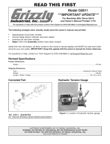
The following changes were recently made to this machine since the owner's manual was printed:
• Changed model of contactor.
• Updated electrical box photo and wiring diagram.
• Changed feed rate dial and feed control knob.
READ THIS FIRST
For questions or help with this product contact Tech Support at (570) 546-9663 or techsupport@grizzly.com
Model G0592
***IMPORTANT UPDATE***
For Machines Mfd. Since 12/08
and Owner's Manual Revised 07/08
COPYRIGHT © JANUARY, 2017 BY GRIZZLY INDUSTRIAL, INC.
WARNING: NO PORTION OF THIS MANUAL MAY BE REPRODUCED IN ANY SHAPE
OR FORM WITHOUT THE WRITTEN APPROVAL OF GRIZZLY INDUSTRIAL, INC.
#BL18767 PRINTED IN TAIWAN
Revised Contactor Part Revised Feed Rate Control Parts
713-2V2
REF PART # DESCRIPTION
713-2V2 P0592713-2V2 CONTACTOR TECO CU-18 24V V2.03.14
The following items have been updated since the last printing of the owner's manual:
• Incorrect information about leveling feet in inventory.
• Incorrect blade selection and speed chart specifications.
Corrected Inventory Item
E. Leveling Feet M12-1.75 x 50 ....................... 4
F. Hex Nuts M12-1.75 ..................................... 4
Aside from this information, all other content in the owner's manual applies and MUST be read and under-
stood for your own safety. IMPORTANT: Keep this update with the owner's manual for future reference.
For questions or help, contact our Tech Support at (570) 546-9663 or [email protected].
REF PART # DESCRIPTION
713-29V2 P0592713-29V2 FEED RATE DIAL V2.12.08
713-30V2 P0592713-30V2 FEED/SPEED CONTROL KNOB V2.12.08
Old New
713-30V2713-29V2713-30713-29

-2-
G0592 Update (Mfd. Since 12/08)
Revised Electrical Components
Figure 51. Inside view of G0592 electrical box.
Contactor
Relay
Transformer
Terminal Block

G0592 Update (Mfd. Since 12/08)
-3-
97N
2T1
2T1
1 L1 3 L2 5 L3
21 NC
4 T2
CU-
18
6 T3
22 NC
14 NO
13 NO
4 6
98NO
95NC 96NC
18
17
16
15
14
12.5
RC A
FN 1748-12
TRIP IND
TEST
CONTROL PANEL (viewed from behind)
Power Light
Limit Switch
E-Stop Button ON Pump
Contactor
Relay
Transformer
Terminal Block
Pump Motor
Motor
7
8
7
4
BLACK
WHITE
GREEN
RED
YELLOW
BLUE
BROWN
COLOR KEY
Bk
Wt
Gn
Rd
Yl
Yl
Yl
Bl
Br
1
3
3
3
7
4
2
3
N
N
N
G
G
G
L
L
L
U1
V1
V2
U2
7
1
Rd
Rd
Rd
Rd
Gn
6
2
3
3
4
7
1
220V
Locking
Shut-off
(as Recommended)
Circuit Breaker
Start
Capacitor
To Control Panel
Br
Bl
Bl
2
Bk
3
2
1
V1
G
2
U1
Rd
Rd
Rd
Rd
Rd
Capacitor
Rd
Yl Yl
G
To Pump Motor
U2
V2
To Motor Junction Box
Revised Wiring Diagram

-4-
G0592 Update (Mfd. Since 12/08)
Corrected Blade Selection & Speed Chart
Copper
Alloy
229~482
(70) (147)
203~213
(62) (65)
85~203
(26) (62)
220
(67)
220~534
(67) (163)
203
(62)
85
(26)
321
(98)
180~220
(54) (67)
95~213
(29) (65)
242
(74)
65~85
(20) (26)
180~220
(54) (67)
75~118
(25) (36)
246
(75)
108~225
(33) (75)
196~354
(60) (108)
203
(62)
111~321
(34) (98)
150~203
(46) (62)
Aluminum
Alloy
Thin
Tube
Angle
Steel
Carbon
Alloy
Speed FPM
(M/Min)
Speed FPM
(M/Min)
Speed FPM
(M/Min)
Speed FPM
(M/Min)
Material
TOOTH SELECTION
CUTTING SPEED RATE RECOMMENDATION
Material Material Material
Tool Steel
Mold Steel
High-Speed
Tool Steel
Alloy
Steel
Water
Hardening
Tool Steel
Stainless
Tool Steel
Cr Stainless
Steel
Free Machining
Stainless Steel
Gray
Cast Iron
Ductile
Austenitic
Cast Iron
Malleable
Cast Iron
Plastics
& Lumber
Cold-Work
Tool Steel
Hot-Work
Tool Steel
Oil-Hardening
Tool Steel
50
2 3 4 5 6 7 8 9 10 11 12 13 14 15 16 17 18 19 2½ 3½
75 100 150 200 250 300 350 400
2/3
2/3
2/3 1.4/2.5
1.4/2.5
1.5/.8
1.5/.8
3/4
3/4
3/4
4/6
4/6
5/8
450
mm
inch
Material Width/Diameter
Material Shapes
Teeth Per Inch (TPI)
Figure 20. G0592 Blade selection and speed chart.

MODEL G0592
10"x18" Metal Cutting Bandsaw
OWNER'S MANUAL
COPYRIGHT © MAY, 2006 BY GRIZZLY INDUSTRIAL, INC. REVISED JULY, 2008 (JM)
WARNING: NO PORTION OF THIS MANUAL MAY BE REPRODUCED IN ANY SHAPE
OR FORM WITHOUT THE WRITTEN APPROVAL OF GRIZZLY INDUSTRIAL, INC.
#PC7789 PRINTED IN TAIWAN

This manual provides critical safety instructions on the proper setup,
operation, maintenance, and service of this machine/tool. Save this
document, refer to it often, and use it to instruct other operators.
Failure to read, understand and follow the instructions in this manual
may result in fire or serious personal injury—including amputation,
electrocution, or death.
The owner of this machine/tool is solely responsible for its safe use.
This responsibility includes but is not limited to proper installation in
a safe environment, personnel training and usage authorization,
proper inspection and maintenance, manual availability and compre-
hension, application of safety devices, cutting/sanding/grinding tool
integrity, and the usage of personal protective equipment.
The manufacturer will not be held liable for injury or property damage
from negligence, improper training, machine modifications or misuse.
Some dust created by power sanding, sawing, grinding, drilling, and
other construction activities contains chemicals known to the State
of California to cause cancer, birth defects or other reproductive
harm. Some examples of these chemicals are:
• Lead from lead-based paints.
• Crystalline silica from bricks, cement and other masonry products.
• Arsenic and chromium from chemically-treated lumber.
Your risk from these exposures varies, depending on how often you
do this type of work. To reduce your exposure to these chemicals:
Work in a well ventilated area, and work with approved safety equip-
ment, such as those dust masks that are specially designed to filter
out microscopic particles.

Table of Contents
INTRODUCTION ............................................................................................................................... 3
Foreword .................................................................................................................................... 3
Contact Info ................................................................................................................................ 3
Machine Data Sheet ................................................................................................................... 4
Identification ............................................................................................................................... 6
Control Panel.............................................................................................................................. 7
SECTION 1: SAFETY ....................................................................................................................... 8
Safety Instructions for Machinery ............................................................................................... 8
Additional Safety Instructions for Metal Cutting Bandsaws ..................................................... 10
SECTION 2: CIRCUIT REQUIREMENTS ...................................................................................... 11
220V Single-Phase................................................................................................................... 11
SECTION 3: SET UP ...................................................................................................................... 12
Set Up Safety ........................................................................................................................... 12
Items Needed for Set Up ......................................................................................................... 12
Unpacking ................................................................................................................................ 12
Inventory ................................................................................................................................... 13
Hardware Recognition Chart .................................................................................................... 14
Clean Up .................................................................................................................................. 15
Site Considerations .................................................................................................................. 15
Moving & Placing Base Unit ..................................................................................................... 16
Mounting to Shop Floor ............................................................................................................ 16
Shipping Bracket ...................................................................................................................... 17
Workstop .................................................................................................................................. 17
Splash Guard ........................................................................................................................... 18
Feed Stop ................................................................................................................................. 18
Recommended Adjustments .................................................................................................... 19
Test Run ................................................................................................................................... 19
SECTION 4: OPERATIONS ........................................................................................................... 20
Operation Safety ...................................................................................................................... 20
Vise .......................................................................................................................................... 20
Cutting Angle ............................................................................................................................ 22
Blade Selection ........................................................................................................................ 23
Blade Speed ............................................................................................................................. 23
Feed Rate................................................................................................................................. 24
Blade Guides ............................................................................................................................ 25
Coolant System ........................................................................................................................ 25

Cutting Fluid ............................................................................................................................ 27
Operation Tips .......................................................................................................................... 27
SECTION 5: ACCESSORIES ......................................................................................................... 28
SECTION 6: MAINTENANCE......................................................................................................... 30
Schedule .................................................................................................................................. 30
Cleaning ................................................................................................................................... 30
Lubrication ................................................................................................................................ 30
SECTION 7: SERVICE ................................................................................................................... 32
Troubleshooting ........................................................................................................................ 32
Blade Change........................................................................................................................... 34
Blade Tension & Tracking ........................................................................................................ 35
Blade Guide Bearings .............................................................................................................. 36
Electrical Components ............................................................................................................. 37
Electrical Components ............................................................................................................. 38
Model G0592 220V Wiring Diagram ........................................................................................ 39
Base Parts Breakdown ............................................................................................................. 40
Base Parts List ......................................................................................................................... 41
Swivel Base Parts Breakdown ................................................................................................. 42
Swivel Base Parts List.............................................................................................................. 43
Vise Parts Breakdown .............................................................................................................. 44
Vise Parts List .......................................................................................................................... 45
Bow Parts Breakdown .............................................................................................................. 46
Bow Parts List .......................................................................................................................... 47
Blade Tension & Motor Parts Breakdown ................................................................................ 48
Blade Tension & Motor Parts List ............................................................................................ 49
Blade Guides Parts Breakdown ............................................................................................... 50
Blade Guides Parts List............................................................................................................ 51
Electrical Parts Breakdown ...................................................................................................... 52
Electrical Parts List ................................................................................................................... 53
WARRANTY AND RETURNS ........................................................................................................ 54

G0592 Metal Cutting Bandsaw
-3-
If you have any comments regarding this manual,
please write to us at the address below:
Grizzly Industrial, Inc.
C
/O Technical Documentation Manager
P.O. Box 2069
Bellingham, WA 98227-2069
We stand behind our machines. If you have any
service questions or parts requests, please call or
write us at the location listed below.
Grizzly Industrial, Inc.
1203 Lycoming Mall Circle
Muncy, PA 17756
Phone: (570) 546-9663
Fax: (800) 438-5901
E-Mail: [email protected]
Web Site: http://www.grizzly.com
Foreword
INTRODUCTION
Contact Info
We are proud to offer the Model G0592 Metal
Cutting Bandsaw. This machine is part of a grow-
ing Grizzly family of fine metalworking machinery.
When used according to the guidelines set forth in
this manual, you can expect years of trouble-free,
enjoyable operation and proof of Grizzly’s com-
mitment to customer satisfaction.
We are pleased to provide this manual with
the Model G0592. It was written to guide you
through assembly, review safety considerations,
and cover general operating procedures. It repre-
sents our effort to produce the best documenta-
tion possible.
The specifications, drawings, and photographs
illustrated in this manual represent the Model
G0592 as supplied when the manual was pre-
pared. However, owing to Grizzly’s policy of con-
tinuous improvement, changes may be made at
any time with no obligation on the part of Grizzly.
For your convenience, we always keep current
Grizzly manuals available on our website at www.
grizzly.com. Any updates to your machine will be
reflected in these manuals as soon as they are
complete. Visit our site often to check for the lat-
est updates to this manual!

-4-
G0592 Metal Cutting Bandsaw
Machine Data Sheet
MODEL G0592 10" X 18" METAL CUTTING BANDSAW
Customer Service #: (570) 546-9663 • To Order Call: (800) 523-4777 • Fax #: (800) 438-5901
MACHINE DATA
SHEET
Product Dimensions:
Weight .............................................................................................................................................................858 lbs.
Length/Width/Height .......................................................................................................................... 74 x 32 x 58 in.
Foot Print (Length/Width) ............................................................................................................................ 45 x 26 in.
Shipping Dimensions:
Type ...................................................................................................................................................Wood Slat Crate
Content ............................................................................................................................................................Machine
Weight ..............................................................................................................................................................967 lbs.
Length/Width/Height ............................................................................................................................ 79 x 36 x 49 in.
Electrical:
Switch ..............................................................................................................................On/Off Located on Saw Bow
Switch Voltage ..................................................................................................................................................... 220V
Cord Length ........................................................................................................................................................... 6 ft.
Cord Gauge .................................................................................................................................................. 14 gauge
Recommended Breaker Size ........................................................................................................................... 20 amp
Plug ........................................................................................................................................................................ Yes
Motors:
Main
Type..................................................................................................................TEFC Capacitor Start Induction
Horsepower ................................................................................................................................................ 2 HP
Voltage....................................................................................................................................................... 220V
Prewired .....................................................................................................................................................220V
Phase ....................................................................................................................................................... Single
Amps ............................................................................................................................................................15A
Speed ................................................................................................................................................ 1720 RPM
Cycle .........................................................................................................................................................60 Hz
Number Of Speeds .......................................................................................................................................... 1
Power Transfer ............................................................................................................................... V-Belt Drive
Bearings ...................................................................................................................... Shielded and Lubricated
Main Specifications:
Operation Info
Blade Speeds ................................................................................................................................. 98-394 FPM
Std. Blade Length ................................................................................................................................... 132 in.
Head Swivel ..........................................................................................................................Right 45°, Left 60°

G0592 Metal Cutting Bandsaw
-5-
Cutting Capacities
Angle Cuts ............................................................................................................................Right 45°, Left 60°
Vise Jaw Depth ..................................................................................................................................... 7-1/2 in.
Vise Jaw Height .......................................................................................................................................... 5 in.
Max Capacity Rect. Height At 90° ........................................................................................................ 9-1/2 in.
Max Capacity Rect. Width At 90° ............................................................................................................. 18 in.
Max Capacity Rnd. Width At 90° .............................................................................................................. 10 in.
Max Capacity Rect. Height At 45° ............................................................................................................ 10 in.
Max Capacity Rect. Height At 30° ............................................................................................................ 10 in.
Max Capacity Rect. Width At 30° ............................................................................................................. 14 in.
Max Capacity Rnd. At 30°......................................................................................................................... 10 in.
Max Capacity Rect. Width At 45° ............................................................................................................. 11 in.
Max Capacity Rnd. At 45°......................................................................................................................... 10 in.
Max Capacity Rect. Height At 60° .............................................................................................................. 5 in.
Max Capacity Rect. Width At 60° ............................................................................................................... 8 in.
Max Capacity Rnd. At 60°........................................................................................................................... 8 in.
Construction
Table Construction ...............................................................................................................................Cast Iron
Wheel Construction Upper ...................................................................................................................Cast Iron
Wheel Construction Lower ...................................................................................................................Cast Iron
Body Construction .........................................................................................................................Formed Steel
Base Construction ............................................................................................................................... Cast Iron
Stand Construction ...................................................................................................................... Formed Steel
Wheel Cover Construction .................................................................................................... Pre-Formed Steel
Paint ........................................................................................................................................................ Epoxy
Other
Blade Guides Upper ........................................................................................................................Ball Bearing
Blade Guides Lower ........................................................................................................................Ball Bearing
Coolant Capacity ....................................................................................................................................... 4 gal.
Table Info
Floor To Cutting Area Height .................................................................................................................... 20 in.
Other Specifications:
Country Of Origin ..............................................................................................................................................Taiwan
Warranty .............................................................................................................................................................1 Year
Serial Number Location ......................................................................................................................Grizzly ID Label
Assembly Time ...........................................................................................................................................90 minutes
Features:
Coolant Pump
Blade Speed Chart
Variable Speed
Adjustable Hydraulic Downfeed
Automatic Shut-off

-6-
G0592 Metal Cutting Bandsaw
Figure 1. G0592 Machine Identification.
A. Blade Tension Handle
B. Lift Handle
C. Vise Handwheel
D. Coolant Pan
E. Work Stop
F. Rotational Degree Scale
G. Spray Gun
H. Electrical Enclosure
I. Speed Adjustment Knob
J. Control Panel
K. Blade Guide Scale
L. Blade Guide Knob
M. Coolant Valve Controls
N. Bow
O. Speed & Blade Selection Chart
P. Blade Guides
Identification
A
C
B
D
E
F
G
H
I
J
K
L
M
O
P
N

G0592 Metal Cutting Bandsaw
-7-
Control Panel
A. Coolant Pump Switch: Turns the coolant
pump ON.
B. EMERGENCY STOP/OFF Button: Interrupts
power to the system and turns the motor
OFF. Twist the button until it pops out to re-
energize the system. Also works as a stan-
dard OFF button.
Note: The bandsaw has an automatic shut-
off (limit switch) that turns the machine OFF
at the completion of the cutting arc.
C. START Button: Turns the motor ON and
activates moving parts.
D. Power Light: When lit, indicates that system
is energized and machine is ready to oper-
ate.
E. Feed Rate Dial: Fine tunes the feed rate by
controlling the hydraulic valve. Range is from
1 being slowest to 9 being fastest.
F. Feed Control Knob: Turning the knob to the
left lowers the bow at the feed rate you have
set. Turning the knob to the right locks the
bow in position.
Figure 2. G0592 control panel.
A
B C D
E
F

-8-
G0592 Metal Cutting Bandsaw
4. ALWAYS USE HEARING PROTECTION
WHEN OPERATING MACHINERY.
Machinery noise can cause permanent
hearing damage.
5. WEAR PROPER APPAREL. DO NOT
wear loose clothing, gloves, neckties, rings,
or jewelry which may get caught in moving
parts. Wear protective hair covering to con-
tain long hair and wear non-slip footwear.
6. NEVER OPERATE MACHINERY WHEN
TIRED, OR UNDER THE INFLUENCE OF
DRUGS OR ALCOHOL. Be mentally alert
at all times when running machinery.
1. READ THROUGH THE ENTIRE MANUAL
BEFORE STARTING MACHINERY.
Machinery presents serious injury hazards
to untrained users.
2. ALWAYS USE ANSI APPROVED
SAFETY GLASSES WHEN OPERATING
MACHINERY. Everyday eyeglasses only
have impact resistant lenses, they are
NOT safety glasses.
3. ALWAYS WEAR AN NIOSH APPROVED
RESPIRATOR WHEN OPERATING
MACHINERY THAT PRODUCES DUST.
Wood dust is a carcinogen and can cause
cancer and severe respiratory illnesses.
For Your Own Safety, Read Instruction
Manual Before Operating this Machine
The purpose of safety symbols is to attract your attention to possible hazardous conditions. This
manual uses a series of symbols and signal words which are intended to convey the level of
importance of the safety messages. The progression of symbols is described below. Remember
that safety messages by themselves do not eliminate danger and are not a substitute for proper
accident prevention measures.
Indicates a potentially hazardous situation which, if not avoided,
MAY result in minor or moderate injury. It may also be used to alert
against unsafe practices.
Indicates a potentially hazardous situation which, if not avoided,
COULD result in death or serious injury.
Indicates an imminently hazardous situation which, if not avoided,
WILL result in death or serious injury.
This symbol is used to alert the user to useful information about
proper operation of the machine.
NOTICE
Safety Instructions for Machinery
SECTION 1: SAFETY

G0592 Metal Cutting Bandsaw
-9-
7. ONLY ALLOW TRAINED AND PROP-
ERLY SUPERVISED PERSONNEL TO
OPERATE MACHINERY. Make sure
operation instructions are safe and clearly
understood.
8. KEEP CHILDREN AND VISITORS AWAY.
Keep all children and visitors a safe dis-
tance from the work area.
9. MAKE WORKSHOP CHILD PROOF. Use
padlocks, master switches, and remove
start switch keys.
10. NEVER LEAVE WHEN MACHINE IS
RUNNING. Turn power OFF and allow all
moving parts to come to a complete stop
before leaving machine unattended.
11. DO NOT USE IN DANGEROUS
ENVIRONMENTS. DO NOT use machin-
ery in damp, wet locations, or where any
flammable or noxious fumes may exist.
12. KEEP WORK AREA CLEAN AND WELL
LIT. Clutter and dark shadows may cause
accidents.
13. USE A GROUNDED EXTENSION CORD
RATED FOR THE MACHINE AMPERAGE.
Undersized cords overheat and lose power.
Replace extension cords if they become
damaged. DO NOT use extension cords
for 220V machinery.
14.
ALWAYS DISCONNECT FROM POWER
SOURCE BEFORE SERVICING
MACHINERY. Make sure switch is in
OFF
position before reconnecting.
15. MAINTAIN MACHINERY WITH CARE.
Keep blades sharp and clean for best and
safest performance. Follow instructions for
lubricating and changing accessories.
16. MAKE SURE GUARDS ARE IN PLACE
AND WORK CORRECTLY BEFORE
USING MACHINERY.
Safety Instructions for Machinery
17. REMOVE ADJUSTING KEYS AND
WRENCHES. Make a habit of checking for
keys and adjusting wrenches before turn-
ing machinery ON.
18. CHECK FOR DAMAGED PARTS
BEFORE USING MACHINERY. Check
for binding and alignment of parts, broken
parts, part mounting, loose bolts, and any
other conditions that may affect machine
operation. Repair or replace damaged
parts.
19. USE RECOMMENDED ACCESSORIES.
Refer to the instruction manual for recom-
mended accessories. The use of improper
accessories may cause risk of injury.
20. DO NOT FORCE MACHINERY. Work at
the speed for which the machine or acces-
sory was designed.
21. SECURE WORKPIECE. Use clamps or
a vise to hold the workpiece when practi-
cal. A secured workpiece protects your
hands and frees both hands to operate the
machine.
22. DO NOT OVERREACH. Keep proper foot-
ing and balance at all times.
23. MANY MACHINES WILL EJECT THE
WORKPIECE TOWARD THE OPERATOR.
Know and avoid conditions that cause the
workpiece to "kickback."
24. ALWAYS LOCK MOBILE BASES
(IF USED) BEFORE OPERATING
MACHINERY.
25. BE AWARE THAT CERTAIN DUST MAY
BE HAZARDOUS to the respiratory sys-
tems of people and animals, especially
fine dust. Make sure you know the hazards
associated with the type of dust you will be
exposed to and always wear a respirator
approved for that type of dust.

-10-
G0592 Metal Cutting Bandsaw
Additional Safety Instructions for Metal
Cutting Bandsaws
8. FIRE HAZARD. Use EXTREME CAUTION
if cutting magnesium. Using the wrong cut-
ting fluid will lead to chip fire and possible
explosion.
9. CUTTING FLUID SAFETY. Always follow
manufacturer’s cutting fluid safety instruc-
tions. Pay particular attention to contact,
contamination, inhalation, storage and dis-
posal warnings. Spilled cutting fluid is a
slipping hazard and a toxicity hazard.
10. ATTENTION TO WORK AREA. Never
leave a machine running and unattended.
Pay attention to the actions of others in the
area to avoid unintended accidents.
11. MAINTENANCE/SERVICE. All inspec-
tions, adjustments, and maintenance are
to be done with the machine OFF and the
power disconnected to the machine. Wait
for all moving parts to come to a complete
stop.
12. HEARING PROTECTION & HAZARDS.
Noise generated by blade and workpiece
vibration, material handling, and power
transmission can cause permanent hear-
ing loss over time and interfere with com-
munication and audible signals. Always
wear hearing protection.
13. HOT SURFACES. Due to friction, the
workpiece, chips, and some machine com-
ponents can be hot enough to burn you.
1. BLADE CONDITION. Do not operate with
dull, cracked or badly worn blade. Inspect
blades for cracks and missing teeth before
each use.
2. HAND PLACEMENT. Never position fin-
gers or thumbs in line with the cut. Hands
could be crushed in vise or by falling
machine components or cut by the blade.
3. ENTANGLEMENT HAZARDS. Do not
operate this bandsaw without blade guard
in place. Otherwise, loose clothing, jewelry,
long hair and work gloves can be drawn
into working parts.
4. BLADE REPLACEMENT. When replacing
blades, make sure teeth face toward the
workpiece. Wear gloves to protect hands
and safety glasses to protect eyes.
5. WORKPIECE HANDLING. Always sup-
port the workpiece with table, vise, or other
support fixture. Flag long pieces to avoid a
tripping hazard. Never hold the workpiece
with your hands during a cut.
6. LOSS OF STABILITY. Unsupported
workpieces may jeopardize machine sta-
bility and cause the machine to tip and fall,
which could cause serious injury.
7. POWER INTERRUPTION. Unplug machine
after power interruption. Machines without
magnetic switches can start up after power
is restored.
No list of safety guidelines can be complete. Every shop environment is different. Like all
machines there is danger associated with the Model G0592. Accidents are frequently caused by
lack of familiarity or failure to pay attention. Use this machine with respect and caution to lessen
the possibility of operator injury. If normal safety precautions are overlooked or ignored, serious
personal injury may occur.

G0592 Metal Cutting Bandsaw
-11-
Serious personal injury could occur if you
connect the machine to the power source
before you have completed the set up pro-
cess. DO NOT connect the machine to the
power source until instructed to do so.
220V Single-Phase
Grounding
In the event of an electrical short, grounding
reduces the risk of electric shock. The grounding
wire in the power cord must be properly connect-
ed to the grounding prong on the plug; likewise,
the outlet must be properly installed and ground-
ed. All electrical connections must be made in
accordance with local codes and ordinances.
Amperage Draw
The Model G0592 motor draws the following
amps under maximum load:
Motor Draw at 220V............................... 15 Amps
Circuit Requirements
We recommend using a dedicated circuit for this
machine. You MUST connect your machine to a
grounded circuit that is rated for the amperage
given below. Never replace a circuit breaker on
an existing circuit with one of higher amper-
age without consulting a qualified electrician to
ensure compliance with wiring codes. If you are
unsure about the wiring codes in your area or
you plan to connect your machine to a shared
circuit, consult a qualified electrician.
220V Circuit ...........................................20 Amps
Plug/Receptacle Type
Recommended Plug/Receptacle ....NEMA L6-20
SECTION 2: CIRCUIT REQUIREMENTS
Electrocution or fire could
result if this machine is
not grounded correctly
or if your electrical con-
figuration does not com-
ply with local and state
codes. Ensure compliance
by checking with a quali-
fied electrician!
Extension Cords
We do not recommend the use of extension
cords. Instead, arrange the placement of your
equipment and the installed wiring to eliminate
the need for extension cords.
If you find it absolutely necessary to use an
extension cord at 220V with your machine:
• Use at least a 12 gauge cord that does not
exceed 50 feet in length!
• The extension cord must also contain a
ground wire and plug pin.
• A qualified electrician MUST size cords over
50 feet long to prevent motor damage.
Grounding Prong
is Hooked
Current Carrying Prongs
L6-20 GROUNDED
LOCKING
RECEPTACLE
L6-20
LOCKING
PLUG
Figure 3.
NEMA L
6-20 plug and receptacle.

-12-
G0592 Metal Cutting Bandsaw
The Model G0592 was carefully packed when it
left our warehouse. If you discover the machine
is damaged after you have signed for delivery,
please immediately call Customer Service at
(570) 546-9663 for advice.
Save the containers and all packing materials for
possible inspection by the carrier or its agent.
Otherwise, filing a freight claim can be difficult.
When you are completely satisfied with the con-
dition of your shipment, you should inventory the
contents.
Wear safety glasses dur-
ing the entire set up pro-
cess!
This machine presents
serious injury hazards
to untrained users. Read
through this entire manu-
al to become familiar with
the controls and opera-
tions before starting the
machine!
Unpacking
Set Up Safety
SECTION 3: SET UP
The following items are needed to complete the
set up process, but are not included with your
machine:
Description Qty
• Safety Glasses (for each person) ............... 1
• Solvent Cleaner .......................................... 1
• Shop Towels ............................................... 1
• Mounting Hardware (optional) .................... 1
• Forklift or hoist ............................................ 1
• Assistant ..................................................... 1
Items Needed for
Set Up
The Model G0592 is
an extremely heavy
machine. Serious per-
sonal injury may occur if
safe moving methods are
not followed. To be safe,
you will need assistance
and power equipment
when moving the ship-
ping crate and remov-
ing the machine from the
crate.

G0592 Metal Cutting Bandsaw
-13-
Inventory
After all the parts have been removed from the
crate, you should have the following items:
Box 1: (Figure 4) Qty
A. Splash Guard ............................................. 1
B. Work Stop Rod ........................................... 1
C. Work Stop Arm ........................................... 1
D. Work Stop ................................................... 1
E. Leveling Feet .............................................. 4
H. Model G0592 Bandsaw (not shown) .......... 1
In the event that any nonproprietary parts are
missing (e.g. a nut or a washer), we would be
glad to replace them, or for the sake of expedi-
ency, replacements can be obtained at your local
hardware store.
Figure 4. G0592 loose inventory.
A
B
C
D
E
NOTICE
Some hardware/fasteners on the inventory
list may arrive pre-installed on the machine.
Check these locations before assuming that
any items from the inventory list are miss-
ing.

-14-
G0592 Metal Cutting Bandsaw
5mm
Hardware Recognition Chart
/