Page is loading ...

Instruction Manual
Inline Exhaust Fan Kit – 100mm & 150mm
Cat. No. EFIL100SQWE, EFIL150SQWE
Read through these instructions completely before commencing installation. Retain for future use.
Cat No. EFIL100SQWE EFIL150SQWE
Supply voltage
230-240V a.c. 50Hz
Power rating
30W 60W
Protection class
Class II
IP rating
IP44
Draught stopper
Yes (PET Sheet)
Duct diameter
Ø100mm Ø150mm
Engine size
290 x 200 x 210mm 290 x 230 x 250mm
Engine weight
1.9kg 3.0kg
Power cord length
1m
Ceiling cut-out size (for inlet & outlet grilles)
Ø110mm Ø160mm
Max airflow (m
3
/hr)
Duct length
Low Speed (I) High Speed (II) Low Speed (I) High Speed (II)
No duct
200 255 450 555
1m per side (total 2m)
100 125 310 390
2.5m per side (total 5m)
90 115 270 335
Specifications
Features
Please Read Carefully
1
2
3
The inline fan is designed to extract steam and odours from a bathroom and expel it to the exterior through an eave outlet. It is also suitable for
extracting air from one room and expelling it to another room (heat distribution).
The fan engine is fitted into the ceiling, well away from the inlet. This inline feature allows the inlet grille to be mounted in wet areas (near the splash
zones of bathrooms) or even above the shower. And because the motor is in the ceiling cavity (away from the inlet grille), noise from the fan is minimal.
1. This product shall be installed in accordance to AS/NZS 3000 Wiring Rules.
2. This product is meant for indoor use only.
3. Regulations concerning the discharge of air must be fulfilled. Local building codes may require venting to the outside.
4. Do not locate the inlet grille above a stove. This product is not to be used in conjunction with a kitchen range hood exhaust system.
5. The minimum length of duct between the fan engine and the inlet / outlet grilles is 200mm.
6. Cross Ventilation:
Ventilation products must have an adequate source of external air to ensure rated performance.

Steam and air will only be exhausted through the fan if there is sufficient flow of air through the room. Ensure adequate inlets exist through windows,
vents or under the door. Airflow path from the inlet to the fan should ideally pass over the source of steam or air to be removed from the room.
Restrictions on replacement air entering the room to be ventilated, or pressure-differentials between the room and outside air will significantly
reduce the exhaust fan’s performance.
7. Unit location:
The fan engine should be positioned at the highest point on the system so the ducting will slope downwards to both grilles. Refer to Fig. 2.
Do not cover the fan engine with thermal insulation. Keep at least 100mm clearance between the engine and thermal insulation.
The fan engine should not be located in an area containing excessive levels of grease.
When choosing a location for the wall switch, ensure it is not within arm’s reach or accessible to a person in a bath or shower.
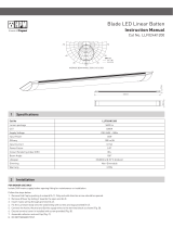
8. Unit Orientation:
The unit must be installed to ensure the fan inlet, outlet and ducting are oriented in parallel to any roofing structures or supports. Refer to Fig. 1 for
correct installation orientation.
Orientation which forces the unit to be ducted into a 90° bend immediately after the fan inlet/outlet will cause a significant performance reduction.
9. Duct Routing:
As the back pressure increases the unit’s performance is reduced. Airflow will be reduced with bends in duct or squashing of duct.
When fitted, the inlet & outlet grilles must be lower than the inline fan engine. Refer to Fig. 2.
The duct must not be installed vertically into a roof vent cap - the product is not designed or intended for this type of installation. Refer to Fig.3.
Fig. 1
Fig. 3
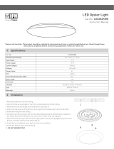
Inlet and Outlet Grilles4
2 types of grilles are supplied with this product.
Fig. 4
Footprint on ceiling: 192 x 192 mm
Protrusion from ceiling: 25 mm
Footprint on ceiling: 188 x 188 mm
Protrusion from ceiling: 17 mm
Fig. 2
Fan engine
Inlet grille
Outlet grille

Fan Engine5
Orientation of the junction box can be adjusted to suit the fan engine’s
mounting location.
1. Unscrew and open the engine clamps.
2. Rotate the Engine to the desired position of the junction box.
3. Replace the engine clamps and tighten the screws.
Fig. 5
Step 1: Remove the louvre
Fig. 5 describes how to mount the grille onto the ceiling/eave.
Step 2: Remove the mesh
Step 3: Attach Body to ceiling/eave using the 4 mounting holes.
Body
Mounting holes
Step 4: Clip on the other grilleStep 4: Replace the mesh and louvre
OR
Air OUTLET
Fig. 6
Grommet for
Power Cord
2 Speed Switch
Draught
Stopper
Mounting
Holes
Air INLET
Grommet for
Power Cord
2 Speed Switch
Impeller
Mounting
Holes
Fig. 7
Engine
Clamps

3)Installa*on
Figure1 Figure2 Figure3
3)Installa*on
Figure1 Figure2 Figure3
3)Installa*on
Figure4 Figure5
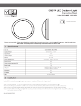
Installation6
Before commencing installation, remove all packaging from the product and ensure that power to the circuit has been isolated.
1. Choose a suitable mounting location for the inlet grille. Ensure there is adequate clearance from studs, pipes, wires etc (Fig. 8).
2. Cut a Ø160mm hole in the ceiling (Fig. 9).
3. Repeat steps 1 & 2 for the outlet grille.
4. Choose a suitable mounting location for the fan engine. Ensure that a power outlet is installed near the intended location of the engine.
5. Mount the engine to a suitable support using the mounting screws provided or other suitable fixings (not provided). The engine should be positioned
so that the power cord is pointing downwards.
6. Stretch, measure and cut the expandable duct to fit between each grille and the fan engine. To obtain optimum performance, the duct should be fully
stretched and without any holes or splits.
7. Attach duct to the outlet grille using the cable ties provided. Pass the duct through the outlet hole and mount the outlet grille to the ceiling / eave.
8. Slide the free end of the duct onto the outlet end of the fan engine and secure it with duct tape.
9. Attach duct to the inlet grille using the cable ties provided. Pass the duct through the inlet hole and mount the inlet grille to the ceiling.
10. Slide the free end of the duct onto the inlet end of the fan engine and secure it with duct tape.
11. Set the Speed Switch to the desired speed (O – Off, I – Low, II – High).
12. Plug the fan engine into the power outlet (Fig. 10).
13. Switch on the inline fan and test function. Use a paper tissue held against the inlet grille to verify suction.
Fig. 8 Fig. 9 Fig. 10
07_2016 HPML0865
LE06397AUB
Warranty
HPM Legrand warrants this product for a period of 5 years from the
date of purchase.
These goods come with guarantees that cannot be excluded under
the Australian and New Zealand Consumer Laws. You are entitled to
a replacement or a refund for a major failure and for compensation
for any other reasonably foreseeable loss or damage. You are also
entitled to have the goods repaired if the goods fail to be acceptable
quality and the failure does not amount to a major failure.
See the Warranty card enclosed with this product for further details.
Customer Service
For all Customer Service and Technical Support
please call Monday to Friday during business hours.
HPM Legrand Australia
1300 369 777
www.hpm.com.au
HPM Legrand New Zealand
0800 476 009
www.hpm.co.nz
ABN: 31 000 102 661
Disclaimers7
1. This product must be installed and used as per these instructions.
2. This product should only be cleaned with a damp cloth. Cleaning agents and solvents should not be used.
3. This product is not intended for use by persons (including children) with reduced physical, sensory or mental capabilities, or lack of experience and
knowledge, unless they have been given supervision or instruction concerning use of the appliance by a person responsible for their safety. Children should
be supervised to ensure that they do not play with the appliance.
4. This product is intended for household use and similar purposes. It is not suitable for use in and environment heavily laden with dust. Under these
conditions the life of the fan motor can be significantly reduced.
5. This product should not be enclosed in thermal insulation as it may cause the unit to overheat.
6. This product has been designed to operate in ambient temperatures 0°C to 40°C.
7. This product contains no serviceable parts and no attempt should be made to repair it. If the product is faulty it should be discarded.
8. If the supply cord is damaged, it must be replaced by HPM Legrand, its service agent or a similarly qualified person in order to avoid a hazard.
9. Airflows listed in this product indicate the product performance. Refer to the BCA (Building Code of Australia), or similar, for the appropriate airflow required
for a particular installation.
10. Ventilation products must have an adequate source of external air to ensure correct performance.
11. Consideration must be taken in the installation of ducts to ensure that condensation that will form in the duct will not run into the fan engine.
12. Precautions must be taken to avoid the back-flow of gases into the room from the open flue of gas or other fuel-burning appliances.
13. This product has been designed for domestic or similar uses and is not suitable for a commercial installation.
14. This product is not suitable for installation in hazardous and/or corrosive areas.
15. Extended exposure to UV rays (such as exposure to direct sunlight) may cause discolouration of this product.
16. The material in this product may vary in colour from batch to batch. Colour matching from one batch to another cannot be guaranteed.
17. This product utilises intellectual property in the form of registered designs, trademarks, and/or patents. Such intellectual property remains the property of
HPM Legrand in all cases.
18. HPM Legrand reserves the right to modify the specification of this product at any time.
/