Hougen 0904101 HMD904 User manual

Category
Power tools
Type
User manual

This manual is also suitable for

PORTABLE MAGNETIC DRILL
OPERATOR’S MANUAL
COVERS DRILL PART NUMBER 0904101, 0904102 & 0904103
FOR USE WITH “12,000-SERIES” HOUGEN
®
CUTTERS
® CUTTERS
®
HMD904 SERIES
2
HOUGEN
Portable Magnetic Drill
Model HMD904 Series
Welcome to Hougen
Congratulations on your purchase of the Hougen
®
Portable Magnetic Drill . Your model is designed to
produce superior holes quickly and effi ciently. Through constant innovation and development, Hougen is
committed to provide you with hole producing tools and products to help you be more productive.
Before attempting to operate your new Portable Magnetic Drill, please read all instructions fi rst. These in-
clude the Operator’s Manual and Warning Label on the unit itself. With proper use, care, and maintenance,
your model will provide you with years of effective hole drilling performance. Once again, thank you for
selecting our product and welcome to Hougen.
Listed below are the Part Numbers and Desciptions of the Hougen HMD904 Series. Please review
Parts Diagram for the location of the Part No./ Serial No. Label.
0904101 (HMD904 Mag Drill 115 volt)
0904102 (HMD904 Mag Drill, 115 volt with coolant)
0904103 (HMD904 Mag Drill, 115 volt with a swivel base)
Cutter Type........................Hougen “12,000-Series”
Hole Capacity....................7/16” to 1-1/2”
Depth of Cut......................2”
Motor.................................450 RPM, 8A
Net Weight.........................27.5 Lbs (HMD904S 30.5 LBS)
Swivel Area........................1-1/8” W x 1-3/8” L
Specifi cations
Hougen Manufacturing, Incorporated warrants its Portable Magnetic Drills and its Electro-hydraulic Hole Punchers for a period
of 1 year and other products for ninety (90) days from date of purchase against defects due to faulty material or workmanship
and will repair or replace (at its option) without charge any items returned. This warranty is void if the item has been damaged
by accident or unreasonable use, neglect, improper service, or other causes not arising out of defects in material or workman-
ship. No other expressed warranty is given or authorized. Hougen Manufacturing, Inc. disclaims any implied warranty of
MERCHANTABILITY or FITNESS for any period beyond the expressed warranty and shall not be liable for incidental or
consequential damages. Some states do not allow exclusions of incidental or consequential damages or limitation on how long
an implied warranty lasts and, if the law of such a state governs your purchase, the above exclusion and limitation may not
apply to you. This warranty gives you specifi c legal rights and you may also have other rights which vary from state to state.
To obtain warranty service, return the item(s), transportation prepaid, to your nearest Factory Authorized Warranty Repair
Center or to Hougen Manufacturing, Inc., 3001 Hougen Drive, Swartz Creek, Michigan 48473.
Hougen Drills are warranted against manufacturing defects only. Subject to Hougen Manufacturing inspection.
THIS WARRANTY IS IN LIEU OF ANY OTHER WARRANTY, EXPRESSED OR IMPLIED, INCLUDING ANY
WARRANTY OF MERCHANTABILITY OR FITNESS FOR A PARTICULAR PURPOSE.
© 2008 Hougen Manufacturing, Inc.
Commercial /
I
ndustrial
L
imited
W
arranty
Photographs and Specifi cations shown are accurate in detail at time of printing. Manufacturer reserves the right to make
improvements and modifi cations without prior notice.
Hougen, Rotabroach, and Hougen-Edge are proprietary trademarks of Hougen Manufacturing Inc.
UNPACKING YOUR NEW MAGNETIC DRILL
1
.
Open shipping carton and remove the literature and
hardware packages.
2.
Read and Follow All Instructions
before attempting
to operate your new Magnetic Drill.
3.
Complete and mail the Product Registration Card
now
.
It is important that Hougen Manufacturing, Inc. have a
record of product ownership.
4.
Open hardware package and check contents.
10565 1/8” Hex wrench for Gib Adjustment
04558 Feed handles (3)
04532 Feed handle knobs (3)
10506 Set screw for cutter installation (2)
10730 Safety chain
02635 Hex wrench for cutter installation
13013 5/32” Hex wrench
5.
Using the handle of Magnetic Drill, lift unit out of the
shipping case.
6.
Remove all packing and securing material from the drill
unit.
7.
Screw the three Knobs (04532) into the three
Feed Handles (04558) and then screw Handles
into the Hub Assembly (40254). Do not overtighten
or may strip the knobs.
8.
Your Magnetic Drill was factory adjusted prior to
shipping. Check to make sure that all gib
adjustment screws, motor mount screws, front
support bracket screws, and magnet mounting
screws are snug and have not vibrated loose in
transit.
9.
Your new Magnetic Drill comes complete with
arbor mounted. The 3/4” diameter arbor bore
ts all 3/4”-shank “12,000-Series” Hougen
Cutters.
Reread Safety Warnings listed in the Operator’s Manual
and on the drill unit to avoid injury. Follow operating
procedures.
3
Always wear eye protection while
using cutting tools, or in the vicin-
ity of cutting.
CAUTION!
The slug is ejected
at the end of the cut. Do not aim
cutter or arbor so that ejected
slug may hit someone around, or
below you.
CAUTION!
Cutters are sharp.
Wear gloves when installing or
removing cutter from arbor. Do
not grab a rotating cutter.
CAUTION!
To prevent electric
shock, do not use power tools
near wet areas, or where power
tool may become wet.
ELECTRICAL PANEL PARTS 11
EXPLODED VIEW HMD904 12
PARTS LISTING HMD904 13
EXPLODED VIEW HMD904C 14
PARTS LISTING HMD904C 15
EXPLODED VIEW HMD904S 16
PARTS LISTING HMD904S 17
DRILL MAINTENANCE & OPERATION HINTS 18
SWIVEL BASE ADJUSTMENT 19
WARRANTY SERVICE CENTERS 20
SAFETY FIRST
WELCOME TO HOUGEN 2
COMMERCIAL WARRANTY 2
UNPACKING YOUR DRILL 3
SAFETY INSTRUCTIONS 4 - 5
SAFETY SWITCH INDICATOR LIGHT 5
OPERATING INSTRUCTIONS 6
INSTALLING HOUGEN CUTTERS 7
ARBOR & GIBS ADJUSTMENT 7
MOTOR EXPLODED VIEW 8
MOTOR PARTS 9
WIRING DIAGRAM 10
INDEX
4
Important Safety Instructions
1. Read All Instructions
2. Grounding Instructions
This tool should be grounded while in use to protect the
operator from electric shock. The tool is equipped with
a 3-conductor cord and a 3-prong grounding type plug
to fi t the proper grounding type receptacle. The green
(or green and yellow) conductor in the cord is the
grounding wire. Never connect the green (or green and
yellow) wire to a live terminal. (Refer to Plug Diagram)
Section A
3. Safe Electrical Connection
Your Mag Drill is rated for use on 115VAC (Plug A) or
230V (Plug B) at 50-60Hz. Do not attempt to use drill on
power sources rated other than this. Wet electrical
connections are shock hazards. To prevent the cutting
uid from traveling along the cord and contacting the
plug or power outlet, tie a drip loop in the power cord.
Also elevate extension cords or gang box connections.
4. Extension Cords
Use only 3-wire extension cords that have 3-prong
grounding type plugs and 3-pole receptacles that
accept the tool’s plug. Replace or repair damaged
cords. Make sure the conductor size is large enough
to prevent excessive voltage drop which will cause
loss of power and possible motor damage.
5. Do Not Force Tool
It will do the job better and faster at the rate for which
it was intended.
6. Keep Work Area Clean
Cluttered areas and benches invite injuries.
Keep dirt and chips from under the Cutter area.
7. Consider Work Area Environment
Do not expose tool to rain.
Do not use tool in damp or wet locations.
Keep work area well lit.
Do not use tool in presence of fl ammable liquids or
gases. Disconnect from power source when changing
cutters or maintaining drill.
8. Guard Against Electric Shock
Prevent body contact with grounded surfaces. For
example: pipes, radiators, ranges, refrigerator
enclosures.
9. Keep Children Away
Do not let visitors contact tool. All visitors should be
kept away from work area while in use.
10. Store Idle Tools
When not in use, tools should be stored in a dry, and
high or locked-up place — out of reach of children.
11. Use Right Tool
Do not force small tool or attachment to do the job
of a heavy duty tool.
Do not use tool for purpose not intended — for
example — do not use a circular saw for cutting tree
limbs or logs.
12. Non-Conforming Cutting Tools
Your Mag Drill is designed to use Hougen Cutters.
The use of drilling tools having different shank styles
is not recommended as they may not tighten securely
in the drill arbor with risk of accident or injury.
13. Secure Work
Use clamps or a vise to hold work. It is safer than
using your hand and it frees both hands to operate
tool.
14. Always Wear Safety Glasses or Goggles
15. Dress Properly
Do not wear loose clothing or jewelry. They might
entangle with spinning chips or get caught in
moving parts. Rubber gloves and nonskid foot
wear are recommended when working outdoors.
Wear sturdy leather gloves when working indoors.
Wear protective hair covering to contain long hair.
16. Do Not Abuse Cord
Never carry drill unit by its cord or yank it to discon-
nect from receptacle.
Keep cord away from heat, oil, and sharp edges.
17. Do Not Overreach
Keep proper footing and balance at all time.
Extension Cord Table
Plugs and Receptacles
HTGNEL
,DROCFO
TEEF
DEDNEMMOCER
ERIW
EGUAG
DEDNEMMOCER
ERIW
EGUAG
ROTOMV511
SPMA21-01
ROTOMV032
SPMA6-5
52OTPU 61 81
05-62 41 81
001-15 01 61
002-101 8 41
003-102 6 21
005-103 4 01
Grounding Pin
Grounding Pin
Grounding
Means
(C)
(A) (B)
(D)
WARNING:
When using electric tools, basic safety precautions should always be followed
to reduce the risk of fi re, electric shock, and personal injury, including the following:
5
26. Circuit Breaker
Changing of the circuit breaker to a higher amp rated breaker, or
bypassing the circuit breaker is not recommended and will void
product warranty.
27. Circuit Breaker Operation
The circuit breaker is a thermal breaker. When it reaches the
higher temperature rating it will trip and cause the unit to shut
down. This is a protective device and can be reset after 5 to 10.
To reset the breaker, press the breaker button back in. If it does
not reset, let the unit cool a little longer until you can push the
button in and it stays n position.
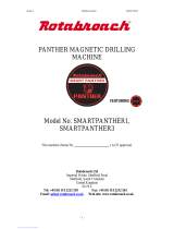
28. Safe Electrical Connection
Wet electrical connections are shock
hazards. To prevent the cutting fl uid
from traveling along the cord and
contacting the plug or power outlet,
tie a drip loop as shown. Also elevate
extension cords or gang box
connections.
29. Save these Instructions.
Important Safety Instructions - Continued
18. Maintain Tools With Care
Keep tools sharp and clean for better and safer
performance.
Do not use
dull or broken Hougen Cutters.
Follow instructions for lubricating and changing
accessories. Inspect tool cords periodically and, if
damaged, have repaired by authorized service facility.
Inspect extension cords periodically and, if damaged,
have repaired by authorized service facility. Keep handles
dry, clean, and free from oil and grease.
19. Disconnect Tools
Disconnect when not in use, before servicing, and
when changing cutters or accessories.
20. Remove Adjusting Keys and Wrenches
Form a habit of checking to see that keys and
wrenches are removed from tool before turning it
on.
21. Check Damaged Parts
Before further use of the drill, a part that is
damaged should be carefully checked to determine
that it will operate properly and perform its intended
function. Check for alignment of moving parts, binding of
moving parts, breakage of parts, mounting, and any
other conditions that may affect its operation. A
part that is damaged should be properly repaired or
replaced by an authorized service center unless
otherwise indicated elsewhere in this operator
manual. Do not operate tool if switch does not turn
it on and off.
22. Stay Alert
Watch what you are doing and use common sense.
Do not operate tool when you are tired.
Have defective switches replaced by authorized
service center.
23. Outdoor Use Extension Cords
When tool is used outdoors, use only extension
cords intended for use outdoors and so marked.
24. Additional Safety Precautions
Arbor and cutter should never be used as a hand-
hold. Keep hands and clothing away from all moving
parts. Do not use Hougen Cutters where ejected slug
might cause injury (slug ejected at end of cut).
Also, adhere to all operating instructions. Do not drill
through any surface that may contain live electrical
wiring. Drilling into a live wire could cause exposed
metal parts of the drill to be made live. Remove chips
wrapped around Cutter and arbor after each hole. With
motor off and power disconnected, grasp chips with
leather gloved hand or pliers and pull while rotating
counterclockwise. Should the cutter become jammed in
the work, stop the unit immediately to prevent personal
injury. Disconnect the drill from the power supply and
loosen jammed cutter by turning the arbor counterclock-
wise. Never attempt to free the jammed cutter by starting
the motor. Service at authorized repair center only.
25. Operating Near Welding Equipment
DO NOT operate this unit on the same work surface that
welding is being performed on. Severe damage to the
unit, particularly the power cord, could occur. This could
also result in personal injury to the operator.
SAFETY SWITCH
INDICATOR LIGHT
The Safety Switch Indicator Light is a Standard Safety
Feature on HMD904 magnetic drills. Its purpose is to inform
the user that an unsafe condition exists.
If light is Green:
In normal operation the safety switch light will be green.
Motor “On” and “Off” Switches function normally.
If light is Red:
A condition with the safety switch exists that needs to be
corrected.
Possible causes:
• Safety Switch is defective. Have drill serviced.
• Uneven work surface or material. Check work
surface for fl atness.
• Dirt or chips under magnet. Clean work surface.
Material should be a least 3/8” thick. Material thinner
than 3/8” will cause a “weak” magnet condition.
HOUGEN MANUFACTURING RECOMMENDS THAT
CONDITIONS ARE CORRECTED SO LIGHT TURNS
GREEN. THIS ALLOWS FOR THE UNIT TO BE
OPERATED IN A SAFE MANNER.
For any questions please contact Hougen Manufacturing’s
Technical Service at (810) 635-7111.
OPERATING INSTRUCTIONS
Always remember that the magnet’s holding power is directly related to the workpiece thickness and surface
condition. Since magnetic attraction diminishes with thinner material or rough surfaces, mechanical clamping of drill unit
to the workpiece should be used when cutting thin material (3/8” or less) or material with uneven surfaces.
1. Make sure workpiece and bottom of magnet are free of chips, oil, etc.
2. Position drill by sliding it and gently feeding Arbor so that pilot point is touching center of hole to be drilled.
3. Secure unit to workpiece with safety chain.
4. Turn magnet ON by pressing the magnet ON switch.
5. Turn Feed Handle, raising the cutter until the pilot is above the work surface.
6. Make certain that cutter is clear of workpiece and turn motor ON by pressing the motor START switch.
7. Feed Hougen Cutter slowly into workpiece. Only after cutting path is established to a depth of about 1/16”
can full force be applied to feed handles.
8.
Ease up on feed pressure
as cutter starts breaking through.
9. At conclusion of cut, turn motor OFF by pressing motor STOP switch. Turn Feed Handles to raise Arbor
thereby ejecting the slug if it hasn’t already fallen free.
10. Turn magnet OFF by pressing the magnet OFF switch.
11.
Disconnect from power source.
12. If necessary, remove chips from cutter and magnet, preferably wearing leather work gloves and/or with pliers.
Disconnect safety chain and you are ready to move unit to new drilling position.
6
OPERATION OF CONTROLS
BEFORE INSTALLING HOUGEN CUTTER
IMPORTANT: Before turning on the machine, it is important that
the operator understands the interrelated functions of the SAFETY
SWITCH, MAGNET SWITCH, AND MOTOR SWITCHES.
READ SAFETY SWITCH INDICATOR LIGHT INSTRUCTIONS
ON PREVIOUS PAGE.
CONTROL PANEL SWITCH PLATE
FIGURE 2
1. Place Magnetic Drill on clean, fl at steel plate that is at least 3/8” thick.
2. Plug unit into proper AC power source.
DO NOT use with DC Power.
3. Locate the Magnet
ON
and
OFF switch
and the motor
STOP
and
START
switch (Fig. 2).
4.
NOTE: A loss of power will de-energize the magnetic base and deactivate the motor. When power is
restored, the magnet will reenergize, however, the motor START switch must be depressed before
the motor will start.
SAFETY SWITCH
— Located in base of drill. Enables motor
operation only when magnet is properly seated on a clean
and fl at work surface. Turns motor off if switch detects lift of
unit.
MAGNET ON/OFF SWITCH
— Energizes and De-energizes
the magnetic base and activates the safety switch. Motor can
now be started by pushing the motor START switch.
MOTOR START/STOP SWITCHES
— Starts and stops the
motor (See instructions previous page).


INSTALLING HOUGEN CUTTER IN ARBOR
1. Disconnect from power source.
2. Lay drill on its side with feed handles up or be sure Arbor clears table if unit is in normal operating position.
3. Turn Feed Handles until cutter mounting set screws are exposed and completely remove the set screws.
4. Insert proper pilot in shank end of Hougen Cutter.
5. Insert Hougen Cutter until fl at on cutter shank is aligned with set screw holes and is exactly perpendicular to
axis of set screw holes.
6. Insert set screws and tighten. Check to be certain that cutter is secure.
7
ADJUSTMENT OF GIBS
1. Loosen all Gib Screws (40237).
2. Feed the drill in and out a few times and then, with top of motor slide fl ush with top of housing, tighten the Gib
Screws until you feel them touch the Steel Gib (02431).
3. Feed the drill in and out again.
4. Adjust Gib Screws so that there is uniform pressure from top to bottom. (Top of motor slide fl ush with top of
housing.)
5. Turn each Gib Screw in about 1/8 to 1/4 turn, depending upon your preference.
6. Gibs should be tight enough so that slide moves up and down smoothly with no wobble or shaking.
(Looseness will cause cutter breakage.)
NOTE: Gibs should be lubricated regularly.
OPERATION OF CUTTING FLUID RESERVOIR
1. With Magnetic Drill in operating position, turn the feed handles so that cutter and pilot are above the work surface.
2. With magnet turned ON and motor OFF, fi ll reservoir by introducing cutting fl uid through slots in Arbor.
Cutting fl uid should not leak out.
3. Test metering capabilities of Arbor/Cutter/Pilot assembly (magnet ON-motor OFF) by feeding the Arbor gently
toward work surface until pilot is pushed up into Cutter, thus allowing fl uid to fi lter down onto work surface
through groove in pilot.
4. For proper lubrication, all cutting fl uid in reservoir should empty onto work surface in no less than 15 seconds
and no longer than 30 seconds.
Adjust Gibs before adjusting front support bracket.
1. Loosen Arbor Support Bracket Bolts.
2. Be sure top of arbor is fl ush with the shoulder on motor output shaft. Also make certain arbor is securely
fastened.
3. Turn feed handle until motor and spindle are at the bottom of their travel.
4. Tighten Arbor Support Bolts.
5. Feed slide up and down a few times, checking for free and uniform movement.
NOTE: Check Arbor support bolts regularly to make certain they are tight. Tighten as required.
ARBOR ADJUSTMENT
Removal
1. Loosen arbor support bracket bolts.
2. Loosen set screws holding arbor onto motor output shaft.
3. Remove arbor.
Installation
1. Hand tighten front support bracket bolts. Do not tighten all the way.
2. Slide arbor to full up position and hold arbor in position over hex drive motor output shaft.
3. Tighten two set screws to hold arbor onto motor output shaft.
4. Turn feed handle until motor and arbor are at the bottom of their travel.
5. Tighten front support bracket bolts to 400 in/lbs.
6. Run motor for 10 seconds. (If visual movement of arbor is noticed, restart at step 1)
7. Re-check for tightness of arbor set screws.
ARBOR & FRONT SUPPORT BRACKET
REMOVAL AND INSTALLATION
MOTOR PARTS DIAGRAM
8
17617
17601
17618
17613
17608
17626
17609
17611
05462
17614
17605
17627
17625
Wires to Motor
Cord
17610
17603
17602
17607
17624
17623
17628
17606
17602
17632
17622
17621
17630
17604
17612
17632
17600
17679
11053
10538
02413
75289
04502
04527
04528 (OPPOSITE SIDE)
Part # Description Qty Part # Description Qty
02413
Motor Cord
1
17611
Key
1
04502
Brush Cover
1
17612
Dowel Pin
1
04527
Label, Motor Specs
1
17613
Flat Washer
1
04528
Label, Motor Safety
1
17614
Gear Housing
1
05462
Spindle
1
17617
Fan Guide
1
10538
Washer #8
1
17618
Gasket
1
11053
Screw BHS #8-32
1
17630
Armature
1
17600
Field Case
1
17628
Field
1
17601
Gear Housing
1
17621
Carbon Brush (Pack of 2)
1
17602
Ball Bearing
2
17622
Brush Cap
2
17603
Ball Bearing
1
17623
Pan Head Screw
2
17604
Ball Bearing
1
17624
Pan Head Screw Short
2
17605
Ball Bearing
1
17625
Pan Head Screw Long
2
17606
Dust Seal
1
17626
Retaining Ring
1
17607
1st Inter. Gear Assy
1
17627
Retaining Ring
1
17608
2nd Inter. Gear Assy
1
17632
Paper Washer
2
17609
Spur Gear
1
17679
Brush Holder
2
17610
Flat Washer
1
75289
Pan Head Screw
2
Qty
Qty
9
11053 BOLT TORQUE SPECIFICATIONS - TIGHTEN TO 18 IN-LBS
75289 BOLT TORQUE SPECIFICATIONS - TIGHTEN TO 25 IN-LBS
MOTOR PARTS LIST - 05477
MOTOR ASSEMBLY
10
J8
J7
Green Ground
To Housing
From L.E.D Bulb
To (J3)
Motor
White Wire
Motor
Black Wire
Safety Switch
Magnet Wires
Power Cord Green
Ground Attach To Housing
Power Cord
White
Power Cord
Black
(P2) Circuit
Board
(P1) Circuit
Board
(J1)
(J2)
(J4)
P2
P1
CONTRO
L
P
ANE
PANEP
L
HOOKUP
 
11



RED ANODE





07011
04643
04644
05872
05871
01226
04614
07012
(3) 02547
05826
04877
WHITE WIRE
04881
04878
04879
90571
Part # Description Part # Description Qty.
01226
Switch Guard
1
05826
Circuit Board
1
02547
#4-40 x 5/16 Screw
3
05871
Motor ON Switch
1
04614
Magnet Switch
1
05872
Motor OFF Switch
1
04643
Red Switch Cover
1
*05205
Green Wire Assembly
1
04644
Green Switch Cover
1
07011
Faceplate
1
04877
Wire Harness
1
07012
Stand-Off 3/16 x 9/16 LG
3
04878
Spacer
1
90571
Power Cord
1
04879
Clear Lens
1
*90690
Cable Tie
1
04881
Bulb L.E.D
1
*not shown
CONTROL PANEL PARTS LIST
Panel Assembly P/N 05188
12
MODEL HMD904 EXPLODED DIAGRAM
*05469 INCLUDES
THESE PARTS
05377
04529
07028 opposite
*05458
*05049
*01439
*10517
*01441
*40312
"12,000 SERIES"
CUTTER
PILOT
40234
04375
10506*
40234
02549
02430
**10538 **11053
10679
02423
02422
04500
90077
10560
40038
02429
07121
02431
40077
90028
40237
90028
02428
02447
75156
50035 40432
41044
10560
40229
40231
**02413
02411 02461
02420
10560
41044
10538
11053
40231
07027 (2)
10977
40254
04558
04532
40398
** INCLUDES
THESE PARTS
05477
04910
17271
10972 04885
04909
10971
10983
*05628
05188
05839
Serial/Part No.
Label
ApprovedApproved
Part # Description Qty
02411
Strain Relief-Motor Cord
1
02413
Motor Cord
1
02420
Motor Cord Clamp
1
02421
Glide Post Spring
2
02422
Motor Cord Bracket
1
02423
Motor Cord Flex Prot.
1
02428
Rack Gear
1
02429
Brass Gib - Right
1
02430
Brass Gib - Left
1
02431
Steel Gib
1
02447
Bolt-Hex Head 1/4-28
2
02461
Screw BHC 1/4-20 x 3/8
2
04375
Front Support Bracket
1
04500
Motor Mount Slide
1
04532
Feed Handle Knob
3
04558
Feed Handle
3
04885
Safety Switch Assy
1
04909
Safety Switch Bracket
1
04910
Plunger Assy
1
05377
Magnet
1
05839
Knob
1
10538
Lock Washer
1
10560
Lock Washer
11
10679
1/4” Flat Washer
1
10971
Screw SHC 1/4-20
2
10972
Screw BHC #6-32
2
10973
Nut
2
10977
Screw BHC 1/4-20
1
10983
Safety Switch Shield
1
11053
Screw BHC #8-32
1
17271
Taper Spring
1
40038
Screw SHC #10-32
2
40077
Screw SHC 1/4-20
1
40214
Screw SHC #6-32
1
Part # Description Qty
40234
Thrust Washer
2
40254
Hub Assy
1
40398
Retaining Ring
1
40432
Screw SHC 1/4-28
1
41044
Screw BHC #10-32
6
50035
Lock Washer 1/4 Ext
4
90028
Lock Washer 1/4 Heli
3
90052
Lock Washer #6 Ext
1
90077
Screw BHC #10-32 x 1/2
1
Assemblies
05477
Motor Assy
07121
Housing Assy
04529
Safety Label
1
07028
Warning Label Chain CSA
1
07027
Warning Label CSA
2
40231
Bronze Bushing
2
40229
Feed Gear
1
40237
Gib Screws
5
05469
Arbor Assembly
01441
Ejector Spring
1
01439
Seat Spring
1
05049
Arbor Spring
1
05458
Arbor Body
1
05628
Set Screws
2
10506
SCR-Set 3/8-24 SPL
2
10517
Retaining Ring
2
40312
Roll Pin Altered
1
02549
Bolt Kit Assembly
02460
Bolt Hex 3/8-24 x 2-3/4
2
40391
Lock Washer 3/8 Heli
2
40392
Washer Flat 3/8
2
05188
Control Panel Assy
HMD904 PARTS LIST
13
14
*05471
** INCLUDES
THESE PARTS
05477
05377
04529
07028 opposite
05188
*05461
*05050
*05054
*10517
05055
40234
04375
10506*
40234
40398
02430
**10538 **11053 10679
02423
02422
04500
90077
10560
40038
02429
10972 04885
04909
10971
10983
07121
02431
40077
90028
40237
90028
02428
02447
75156
50035
40432
41044
10560
40229
40231
02413
02411
02461
02420
10560
41044
10538
11053
40231
07027 (2)
40254
04558
04532
40398
04910
17271
40302
40301
40300
40300
40295
40301
40302
40303
40332
05988
HOOKS TO
COOLANT
INDUCER
05060
02549
05057
40038 10560
05058
*04986
05061
05059
*05358
*05628
**04391
05839
Serial/Part No.
Label
MODEL HMD904C EXPLODED DIAGRAM
ApprovedApproved
15
Part # Description Qty
02411
Strain Relief-Motor Cord
1
02413
Motor Cord
1
02420
Motor Cord Clamp
1
02422
Motor Cord Bracket
1
02423
Motor Cord Flex Prot.
1
02428
Rack Gear
1
02429
Brass Gib - Right
1
02430
Brass Gib - Left
1
02431
Steel Gib
1
02447
Bolt-Hex Head 1/4-28
2
02461
Screw BHC 1/4-20 x 3/8
2
04375
Front Support Bracket
1
04500
Motor Mount Slide
1
04532
Feed Handle Knob
3
04558
Feed Handle
3
04885
Safety Switch Assy
1
04909
Safety Switch Bracket
1
04910
Plunger Assy
1
05055
Collar
1
05377
Magnet
1
05839
Knob
1
10538
Lock Washer
1
10560
Lock Washer
11
10679
1/4” Flat Washer
1
10971
Screw SHC 1/4-20
2
10972
Screw BHC #6-32
2
10973
Nut
2
10977
Screw BHC 1/4-20
1
10983
Safety Switch Shield
1
11053
Screw BHC #8-32
1
17271
Taper Spring
1
40038
Screw SHC #10-32
2
40077
Screw SHC 1/4-20
1
40214
Screw SHC #6-32
1
40234
Thrust Washer
2
40254
Hub Assembly
1
40398
Retaining Ring
1
40432
Screw SHC 1/4-28
1
41044
Screw BHC #10-32
6
50035
Lock Washer 1/4 Ext
4
Part # Description Qty
90028
Lock Washer 1/4 Heli
3
90052
Lock Washer #6 Ext
1
90077
Screw BHC #10-32 x 1/2
1
Assemblies
05477
Motor Assy
07121
Housing Assembly
04529
Safety Label
1
07028
Warning Label CSA
1
07027
Warning Label Chain CSA
2
40231
Bronze Bushing
2
40229
Feed Gear
1
40237
Gib Screws
5
05471
Arbor Assembly
05050
Spring Compression
1
05054
Seat Spring
1
05461
Arbor Body
1
05628
Set Screws
2
04986
Rubber Washer
1
10506
SCR-Set 3/8-24 SPL
2
10517
Retaining Ring
1
05358
Washer, Shim
1
40332
Inducer Collar Assy.
40295
Collar Inducer
1
40300
“O” Rings
2
40302
Ring Retaining
2
40301
Washer
2
40303
Fitting - Tube
1
05060
Bottle-Coolant Assy.
05064
Bottle - Round
1
05059
Holder - Coolant Btl
1
05061
Knob-Thumb Screw
1
40429
Nut Locking 1/8 NPT
1
04391
“O” Ring
1
05065
Ball - Valve Assy
1
05067
Fitting Brass Barb
1
40304
Tubing - Viny’
1
05188
Control Panel Assy
1
HMD904C PARTS LIST
*05469 INCLUDES
THESE PARTS
** INCLUDES
THESE PARTS
05477
04530 (2)
05188
*05458
*05049
*01439
*10517
*01441
*40312
"12,000-SERIES"
CUTTER
PILOT*
40234
05734
10506*
40234
05736
02429
**10538
**11053
10679
02423
02422
05824
90077
10560
40038
02430
04541
02431
40237
05825
02447
75156
50035
40432
40229
40231
02413
02411
02461
02420
10560
41044
10538
11053
40231
04529
40254
04558
04532
40398
05649
40077
90028
*05628
05652#
05743 (6)
05670#
05653#
# Included with assembly
Magnet Assy
05658
40391
40392
05659
05656
05657
40398
90028
10560
41044
05839
07015


MODEL HMD904S EXPLODED DIAGRAM
16
Part # Description Qty
02411
Strain Relief-Motor Cord
1
02413
Motor Cord
1
02420
Motor Cord Clamp
1
02422
Motor Cord Bracket
1
02423
Motor Cord Flex Prot.
1
05669
Rack Gear
1
02429
Brass Gib - Right
1
02430
Brass Gib - Left
1
02431
Steel Gib
1
02447
Bolt-Hex Head 1/4-28
2
02461
Screw BHC 1/4-20 x 3/8
2
04532
Feed Handle Knob
3
04558
Feed Handle
3
05656
Swivel Plate
1
05657
Slide Plate
1
05658
Pivot Rod
1
05659
Clamp Handle Asembly
1
05734
Front Support bracket Assy
1
05736
Bolt Hex Head 3/8-24 x 2”
2
05743
Screw-FHSC 1/4-20 x 3/4
6
05824
Motor Mount Slide
1
05825
Rack Gear
1
05839
Knob
1
10538
Lock Washer
1
10560
Lock Washer
11
10679
1/4” Flat Washer
1
10971
Screw SHC 1/4-20
2
10972
Screw BHC #6-32
2
10973
Nut
2
10977
Screw BHC 1/4-20
1
10983
Safety Switch Shield
1
11053
Screw BHC #8-32
1
17271
Taper Spring
1
40038
Screw SHC #10-32
2
40077
Screw SHC 1/4-20
1
40214
Screw SHC #6-32
1
40234
Thrust Washer
2
40254
Hub Assy
1
Part # Description Qty
40398
Retaining Ring
1
40432
Screw SHC 1/4-28
1
41044
Screw BHC #10-32
6
50035
Lock Washer 1/4 Ext
4
90028
Lock Washer 1/4 Heli
3
90052
Lock Washer #6 Ext
1
90077
Screw BHC #10-32 x 1/2
1
Assemblies
05649
Magnet Assembly
05650
Magnet
1
05652
Safety switch Assembly
1
05653
Plunger
1
05670
Ring, Retaining
1
05477
Motor Assy
04541
Housing Assy
04529
Safety Label
1
04530
Warning Label
2
04553
Warning Label Chain
1
40231
Bronze Bushing
2
40229
Feed Gear
1
40237
Gib Screws
5
05469
Arbor Assembly
01441
Ejector Spring
1
01439
Seat Spring
1
05049
Arbor Spring
1
05458
Arbor Body
1
05628
Set Screws
2
10506
SCR-Set 3/8-24 SPL
2
10517
Retaining Ring
2
40312
Roll Pin Altered
1
05188
Control Panel Assy
HMD904S PARTS LIST
17
1. Keep insides of Hougen Cutter clear of chips. Chips will interfere with cutting to maximum depth, may impede
the free oil fl ow and can cause cutter breakage.
2. Keep work, machine, arbor and Hougen Cutter free of chips and dirt.
3. Tighten all bolts and fasteners regularly.
4. We highly recommend using a light viscosity cutting fl uid (preferably
Hougen Cutting Fluid - Part No. 11742-4)
5. Occasionally check metering of cutting fl uid fl ow. Lack of cutting fl uid may
cause Hougen Cutter to freeze in cut, slug to stick and may result in poor
cutter life.
6. Always start cut with light feed pressure and then increase suffi ciently to
achieve maximum cutting rate.
7. Ease off on pressure as cutter begins to break through at the end of the cut.
8. Keep slide dovetails, brass gibs and feed rack lubricated and free of chips and dirt.
9. When slug hangs up in cutter, turn off motor and bring cutter down on a fl at surface. This will normally straighten a
cocked slug, allowing it to be ejected.
10. When cutting large diameter or deep holes it may be necessary to stop in the middle of the cut to add cutting
uid and remove the chips from around the arbor. (When doing this DO NOT raise the cutter out of the hole.
Doing so can allow chips to get under the teeth of the cutter and make it diffi cult to restart the cut.)
* ”Babying” the cutter through the cut will only decrease tool life.
MAINTENANCE
In order to minimize wear on moving parts and to insure smoother operation and longer life for your magnetic drill,
the following maintenance should be done periodically, based on use.
1. Regularly tighten all fasteners and replace all worn parts.
2. Check motor brushes and replace if worn. (Break in period - 30 minutes at no load speed)
3. Check power cord and cord from panel to motor and, if cracked or frayed, return to an authorized repair center for
replacement.
4. Apply grease to the slide dovetails, brass gibs, and the feed gear rack. For best results use Shell Cyprina-RA or
equivalent.
5. Remove arbor and pack the bearing in the front support bracket with grease. Use Shell Cyprina-RA or equivalent.
HINTS FOR SMOOTHER OPERATION
REMEDIES FOR HOLEMAKING PROBLEMS
1.
Trouble: Magnetic base won’t hold effectively to work
.
a. Cause: Chips or dirt under magnet.
Remedy
: Clear area of chips and dirt.
b. Cause: Irregular surface on bottom of magnet
or on workpiece.
Remedy:
Lightly surface grind the bottom of the
magnet fl at and/or fi le imperfections
at on the work surface as needed.
2. Trouble: Cutter tends to move across surface
of work.
a. Cause: Magnetic base not holding effectively.
Remedy:
See causes and remedies under No. 1
above.
b. Cause: Too much feed pressure at start of cut.
Remedy:
Light pressure until a groove is cut.
The groove then serves as a stabilizer.
c. Cause: Worn pilot.
Remedy:
Replace pilot
3. Trouble: Out of round holes.
a. Cause: Worn arbor support bracket bearing
and or ejector collar.
Remedy:
Replace: (only a few thousandths
wear permissible.)
b. Cause: Misaligned support bracket
Remedy:
Realign support bracket
c. Cause: Misaligned or loose arbor set screws.
Remedy:
Tighten set screws.
4. Trouble: Motor and slide won’t stay in set position
a. Cause: Gibs too loose
Remedy
: Adjust gibs
5.
Trouble: Erratic or intermittent feed.
a. Cause: Worn or pinion and/or rack.
Remedy:
Replace worn parts.
6. Trouble: Motor doesn’t run when motor START
button is pushed.
a. Cause: Magnet is not turned on
Remedy
: Push magnet ON button.
b. Cause: Magnet on rough or dirty work surface
and safety switch not fully depressed.
Remedy:
File work surface fl at and clean all
chips and oil from under magnet.
c. Cause: No power
Remedy:
Check power source and extension
cords.
e. Cause: Worn motor brushes
Remedy:
Replace brushes
f. Cause: Faulty motor START switch
Remedy:
Return unit to an authorized repair
center to have switch replaced.
NOTE: If you are unable to correct any malfunction
after trying the above, do not attempt to operate the
drill. Return the unit to the factory or authorized repair
c. Cause: Misaligned or loose arbor set screws.
drill. Return the unit to the factory or authorized repair
c. Cause: Misaligned or loose arbor set screws.
center for service.
18
#1 cause of cutter
breakage and
prematurely dull
teeth is too little
feed pressure*
19
SWIVEL BASE ADJUSTMENTS
To Loosen the Swivel Plate Assembly
1. Lift the Clamp Handle Assembly,
rotated counter-clockwise and release .
This will reposition the lever
for more movement.
With this being a left handed thread this will loosen this assembly.
3. If more travel is needed lift the Clamp Handle Assembly, rotate counter clockwise
and release.
4. Pull the Clamp Handle Assembly clockwise again.
This amount of movement should be adequate to reposition the Drill Assembly.
More movement than this may cause the Magnet Assembly to disengage from the drill base.
To Tighten the Swivel Plate Assembly.
1. Lift the Clamp Handle Assembly,
rotated clockwise and release .
This will reposition the lever
for more movement.
With this being a left handed thread this will tighten this assembly.
3. If more travel is needed lift the Clamp Handle Assembly, rotate clockwise and release.
4. Push the Clamp Handle Assembly counter clockwise again.
Continue this process until the Swivel Assembly is tight.
WARNING :
2. With the Clamp Handle Assembly now down,
pull the Clamp Handle Assembly clockwise.
2. With the Clamp Handle Assembly now down,
push the Clamp Handle Assembly counter clockwise.
CLAM
P
HANDLE MUST BE TIGHT PRIOR
T
O CUTTING HOLES -
EQUIPMENT DAMAGE OR PERSONA
L
INJU
R
Y
RYR
COULD OCCUR
Y COULD OCCUR Y
ATTENTION
The threads on the Clamp Handle Assembly are a Left Handed thread meaning,
Turning Clockwise would loosen the assembly
Turning Counter Clockwise would tighten the assembly.
Also, the Clamp Handle Assembly is spring loaded so you will need to lift & turn the entire
Clamp Handle Assembly when repositioning as if to be a ratchet device.
  • Page 1 1
  • Page 2 2
  • Page 3 3
  • Page 4 4
  • Page 5 5
  • Page 6 6
  • Page 7 7
  • Page 8 8
  • Page 9 9
  • Page 10 10
  • Page 11 11
  • Page 12 12
  • Page 13 13
  • Page 14 14
  • Page 15 15
  • Page 16 16
  • Page 17 17
  • Page 18 18
  • Page 19 19

Hougen 0904101 HMD904 User manual

Category
Power tools
Type
User manual
This manual is also suitable for

Ask a question and I''ll find the answer in the document

Finding information in a document is now easier with AI