Page is loading ...

ML434 | v36 15-Nov-19
D758/ET MiniPurge®
Manual
ML434
Important Note:
It is essential for safety that the installer and user of the Expo system follow these
instructions.
Please refer to the standard for principles and definition.
These instructions apply only to the pressurizing system. it is the responsibility of the
manufacturer of the pressurized enclosure to provide instructions for the enclosure.
Expo Technologies reserves the right to replace any component, with one of the equivalent functionality.


ML434 | v36 i
Section 1: System Specification................................................................................................1
MiniPurge® Control Unit Data...................................................................................................2
Relief Valve Unit and Purge Outlet Valve with integral spark arrestor......................................3
Section 2: Quick User Guide......................................................................................................4
Installation ................................................................................................................................4
Operation of the System...........................................................................................................4
Section 3: Application Suitability ..............................................................................................6
Section 4: Description and Principle of Operation ..................................................................7
Section 5: Main Components.....................................................................................................8
Air Supply Filter / Regulator......................................................................................................8
Logic Air Supply Regulator .......................................................................................................8
Minimum Pressure Sensor .......................................................................................................8
Purge Flow Sensor ...................................................................................................................8
Intermediate Sensor .................................................................................................................9
Electronic Purge Timer .............................................................................................................9
Purge Complete Valve..............................................................................................................9
OR Gate ...................................................................................................................................9
Alarm Only Circuit (/AO) ...........................................................................................................9
Visual Indicators .....................................................................................................................10
Power Interlock Switch ...........................................................................................................10
Alarm / Pressurized Switch.....................................................................................................10
System Purging Switch (Optional)..........................................................................................10
Intermediate Switch ................................................................................................................10
Purge Valve ............................................................................................................................10
Purge Flow Restrictor .............................................................................................................10
CLAPS Sensor .......................................................................................................................11
CLAPS Regulator ...................................................................................................................11
Relief Valve Unit .....................................................................................................................11
/PA Terminal Box....................................................................................................................11
Section 6: Installation of the System.......................................................................................11
Relief Valve Unit .....................................................................................................................11
Air Supply Quality ...................................................................................................................12
Pipe Work ...............................................................................................................................12
Multiple Enclosures ................................................................................................................13
Provision and Installation of Alarm Devices ...........................................................................13
Power Supplies and their Isolation .........................................................................................13
Power Interlock Switch ...........................................................................................................13
Section 7: Commissioning .......................................................................................................14
Commissioning the System ....................................................................................................14
Normal Operation ...................................................................................................................15
Section 8: Maintenance of the System....................................................................................16
General maintenance .............................................................................................................16
Additional maintenance checks ..............................................................................................16
Maintenance of Electronic Timer ............................................................................................16
Re-calibration of the Relief Valve Unit....................................................................................16
Re-calibration of the Pressure Sensors..................................................................................17
Section 9: Fault Finding............................................................................................................18
General Information................................................................................................................18
System purges correctly but trips and auto re-purges at the end of the purge time...............18
Relief Valve opens (continuously or intermittently).................................................................19
System enters purging but purge indication does not occur...................................................19
System begins purging but cycles fail to complete.................................................................19
Section 10: Recommended Spares List..................................................................................20
Section 11: Glossary.................................................................................................................20
Section 12: Drawings and Diagrams .......................................................................................20
Section 13: Certifications .........................................................................................................21

Page
1
ML434 | v36
Expo Technologies UK
T: +44 (0) 20 8398 8011
E: sales@expoworldwide.com
Expo Technologies US
T: +1 (440) 247 5314
Expo Technologies China
T: +86 532 8906 9858
E: qingdao@expoworldwide.com
Section 1: System Specification
5 X LC / ss / ET / OV / PC / PA
Size
5 = MiniPurge®
Purge flow rate:
6000 NI/min
Approval / Certification
Sira 01ATEX1295X
2813 II 2(2) GD
Ex [pxb] ia IIC T5 Gb
Ex [pxb] ia IIIC T100ºC Db
Tamb -20ºC to +55ºC
IECEx SIR07.0027X
Ex [pxb] ia IIC T5 Gb
Ex [pxb] ia IIIC T100ºC Db
Tamb -20ºC to +55ºC
TÜV 12.1462X
Ex [pxb] ia IIC T5 Gb
Ex [pxb] ia IIIC T100ºC Db
Tamb -20ºC to +55ºC
PC = Pressurized Control. Automatic
leakage compensation (CLAPS)
OV = Purge Outlet Valve is
pneumatically operated
Timing Method
ET = Electronic Timer
MiniPurge® Housing
ss = Stainless Steel 316L
Pressurization Method
LC = Leakage Compensation
ATEX Certificate:
IECEx Certificate:
TÜV INMETRO Certificate:
PA = Power and Alarm Switches.
Integral /PA Terminal Box
For limitations and
conditions of use refer to
the applicable certificates.

ML434 | v36 Page
2
Expo Technologies UK
T: +44 (0) 20 8398 8011
Expo Technologies US
T: +1 (440) 247 5314
Expo Technologies China
T: +86 532 8906 9858
MiniPurge® Control Unit Data
Action on Pressure Failure: Alarm and Trip (isolate power to pressurized enclosure), user adjustable
Alarm Only.
Type of Operation: Automatic leakage compensation using the Closed Loop Automatic
Pressurization System (CLAPS System).
Leakage Compensation
Capacity
1500 NI/min max.
Enclosure Material: Stainless Steel 316L.
Mounting Method: Wall mounting straps. Fixing holes as per drawing.
Temperature Limits: -20oC to +55oC
Compressed Air Supply: Clean, dry, oil free air or inert gas. Refer to Air Supply Quality section in
Installation of the System.
Supply Pressure: 5 to 16 barg (73 to 232 psi).
Main Regulator: Set at 5 barg, 40 μm automatic drain supply inlet filter.
Logic Regulator and Gauge: Fitted and set to 2.5 barg (36 psi).
Process Connections: Purge supply and outlet to pressurized enclosure 1” NPT female.
Minimum supply line 25 mm (1”) ID tube, inlet sized appropriately for flow
rate.
Reference points & signals 1/8” NPT female, minimum 6 mm pipe to be
used.
Visual Indicators: Alarm (Red ) / Pressurized (Green ).
System Purging: 4 LEDs that flash sequentially to indicate elapsed time
(black when not purging).
/PA Terminal Box: Stainless Steel, Ex e IIC T5 Gb / Ex tb IIIC T100ºC Db IP66 Tamb : -20ºC
to +55ºC with terminals, front access cover & lower removable gland
plate.
Stainless Steel, Ex e IIC T4 Gb Tamb : -20ºC to +60ºC with terminals,
front access cover & lower removable gland plate.
Power Interlock Switch: DPNO switch, contact ratings 250 Vac 4 Amps (AC-15) / 24V DC 4A,
Ex d IIC T6 Gb / Ex tb IIIC T80ºC Db.
Alarm Switch: SPCO switch, contact ratings 250 Vac 4 Amps (AC-15) / 24V DC 4A,
Ex d IIC T6 Gb / Ex tb IIIC T80ºC Db.
Intermediate Switch: SPCO switch, contact ratings 250 Vac 4 Amps (AC-15) / 24V DC 4A,
Ex d IIC T6 Gb / Ex tb IIIC T80ºC Db.
System Purging Switch
(Optional):
SPCO switch, contact ratings 250 Vac 4 Amps (AC-15) / 24V DC 4A,
Ex d IIC T6 Gb / Ex tb IIIC T80ºC Db.
Minimum Pressure Sensor: Minimum: 0.5 mbarg.
Maximum: 5.0 mbarg.
Default Setting: 1.5 mbarg.
Tolerance -0, +0.7 mbarg.
Intermediate Sensor: Minimum: 2.0 mbarg.
Maximum: 10 mbarg.
Default Setting: 5.0 mbarg.
Tolerance: -0, +10%.
Note: There must be a 1.5 mbarg difference between the minimum pressure and intermediate sensors.
Purge Flow Sensor: Set at 6.4 mbarg (Tolerance: -0, +10%).

Page
3
ML434 | v36
Expo Technologies UK
T: +44 (0) 20 8398 8011
E: sales@expoworldwide.com
Expo Technologies US
T: +1 (440) 247 5314
Expo Technologies China
T: +86 532 8906 9858
E: qingdao@expoworldwide.com
Relief Valve Unit and Purge Outlet Valve with integral spark arrestor
Note: Special settings available on request, refer to Test and Inspection Sheet.
CLAPS Sensor: Minimum: 5.0 mbarg.
Maximum:15 mbarg.
Default Setting: 10 mbarg.
Tolerance: -0, +10%
Note: there must be a 2.5 mbarg difference between the intermediate and CLAPS sensor calibration point.
For example: Minimum pressure = 5 mbarg, intermediate pressure = 6.5 mbarg, CLAPS sensor = 9 mbarg.
Purge Time: User selectable, in 1 minute intervals, up to 99 minutes (tolerance -0, +3
seconds).
Default Setting 99 minutes.
Weight: 27 kg (60lb).
Type: RLV104/ss/FS, Design number D758RLV.
Bore: Purge Outlet Valve Ø 104 mm, Relief Valve Ø 75 mm.
Relief Valve Lift-Off Pressure: Minimum: 20 mbarg.
Maximum: 50 mbarg.
Default: 30 mbarg (+0, -20%).
Flow Rate: Range: 2000, 3000, 4000, 5000, or 6000 NI/min.
Default: 2000 NI/min.
Material: Housing: Stainless steel 316L.
Gasket: Silicone foam.
Spark arrestor: Stainless steel mesh.
Mounting Method: Rectangular cut-out and fixing holes as per drawing.
Weight: 7 kg (15.4 lb).

ML434 | v36 Page
4
Expo Technologies UK
T: +44 (0) 20 8398 8011
Expo Technologies US
T: +1 (440) 247 5314
Expo Technologies China
T: +86 532 8906 9858
Section 2: Quick User Guide
Installation
The MiniPurge® System must be installed by a competent engineer, in accordance with relevant standards,
such as IEC / EN 60079-14 and any local codes or practice.
• Mount the purge system in accordance with the hook-up drawing.
• Ensure the system is installed according to the full instructions in the “Installation of the System” section of
this manual.
• All pipings must be clean and free of dirt, condensation and debris prior to connection to the purge system
or pressurized enclosure.
• It is strongly recommended that a local isolation valve is installed on the air supply upstream of the purge
system.
Note: Most faults are due to restricted air supply, inadequate supply pipe work or drop in air supply
pressure during the purge process.
Operation of the System
Once the system is installed correctly, turn on the air supply. Refer to Commissioning section.
The purge system commences the purge cycle:
• The purge air will enter the enclosure.
• The pressurized enclosure will obtain a positive pressure.
• The Purge Outlet Valve will open within the Relief Valve Unit.
• The air will then exit the Relief Valve Unit housing via the spark arrestor.
Open the Purge Flow Restrictor Valve until the air flow reaches the required rate; the system will initiate the
timed purge cycle. Start a stopwatch when the purging indicator flashes yellow
On completion of an uninterrupted purge cycle of the required length, the system will indicate purge complete.
Indicator Colour Status
Alarm / Pressurized Red Low pressure alarm (enclosure pressure too low)
Purging Black Purge flow too low or not in purge mode
Indicator Colour Status
Alarm / Pressurized Green Pressurized (minimum enclosure pressure achieved)
Purging Black Purge flow too low
Indicator Colour Status
Alarm / Pressurized Green Pressurized
Purging Sequential flashing
Yellow
Purge flow rate above minimum

Page
5
ML434 | v36
Expo Technologies UK
T: +44 (0) 20 8398 8011
E: sales@expoworldwide.com
Expo Technologies US
T: +1 (440) 247 5314
Expo Technologies China
T: +86 532 8906 9858
E: qingdao@expoworldwide.com
Stop the stopwatch when the purging indicator stops flashing.
Check stopwatch timing to verify that the actual purge time is equal to or greater than the required purge time.
Note: The recorded purge time must never be less than the required purge time.
The system is now operating correctly in leakage compensation mode.
If the system has not performed as expected, check the installation thoroughly and ensure it has been carried
out according to the instructions.
If an obvious problem has not been highlighted and corrected, follow the procedures in the Fault Finding
section.
If all checks have been carried out and the system still does not perform as expected, contact your local
distributor or Expo Technologies.
Indicator Colour Status
Alarm / Pressurized Green Pressurized and in leakage compensation mode
Purging Black No longer in purge mode

ML434 | v36 Page
6
Expo Technologies UK
T: +44 (0) 20 8398 8011
Expo Technologies US
T: +1 (440) 247 5314
Expo Technologies China
T: +86 532 8906 9858
Section 3: Application Suitability
MiniPurge® systems are certified for use in hazardous locations, where the hazardous location is non-mining
(above ground) and the hazard is caused by flammable gasses, vapours or dust. Depending on the model the
systems may be used in IECEx and ATEX Zone 1 and/or Zone 2 - Categories 2 and 3 respectively.
MiniPurge® systems may be used for hazards of any gas group. Apparatus associated with the MiniPurge®
system, such as intrinsically safe signalling circuits and flameproof enclosures containing switching devices
may be limited in their gas group. The certification documentation supplied with any such devices must be
checked to ensure their suitability.
This system is primarily designed for use with compressed air. Where other inert compressed gasses are
used (Nitrogen, for example) the user must take suitable precautions so that the build up of the inert gas does
not present a hazard to health. Consult the Control of Substances Hazardous to Health (COSHH) data sheet
for the gas used. Where a risk of asphyxiation exists, a warning label must be fitted to the pressurized
enclosure.
The following materials are used in the construction of MiniPurge® systems. If substances that will adversely
affect any of these materials are present in the surrounding environment, please consult Expo Technologies
for further guidance.
Materials of Construction
Stainless Steel Aluminium Acrylic
Mild (Carbon) Steel Nylon Silicone
Brass Polyurethane Neoprene
ABS Polycarbonate Polyester (glass filled)

Page
7
ML434 | v36
Expo Technologies UK
T: +44 (0) 20 8398 8011
E: sales@expoworldwide.com
Expo Technologies US
T: +1 (440) 247 5314
Expo Technologies China
T: +86 532 8906 9858
E: qingdao@expoworldwide.com
Section 4: Description and Principle of Operation
The MiniPurge® system is pneumatic in operation, with electrical interfaces.
Purge and pressurization is a method of protection used in Zone 1 (21) and/or Zone 2 (22) hazardous
locations to ensure that the interior of an enclosure is free of flammable gas. Addition of a MiniPurge® system
allows the electrical equipment within the enclosure to be used safely in a hazardous location.
The principle of purge and pressurization is as follows:
• Clean compressed air or inert gas is drawn from a non-hazardous location.
• The interior of the pressurized enclosure is flushed to remove any hazardous gas or dust.
• This is introduced into the pressurized enclosure to keep the internal pressure at least 0.5 mbarg above
the external pressure.
• Whilst pressurized, flammable gas cannot enter the enclosure from the environment.
Prior to switching on the power to the electrical equipment, the enclosure must be purged to remove any
flammable gas that might have entered the enclosure before pressurization. Purging is the process of removal
contaminated air and replacement with air (or inert gas) known to be free from flammable gas. The duration
of this purge process is normally ascertained by performing a purge test.
At the end of the purge cycle the system automatically switches to leakage compensation mode. The Purge
Outlet Valve is closed and the airflow is reduced but remains high enough to compensate for the leakage of
air from the enclosure whilst maintaining the minimum over pressure state.
In the event of pressure failure within the pressurized enclosure the system will raise an alarm in the form of
visual indicators and a volt free contact depending on the specification of the system. The default action on
loss of pressurization is alarm and automatic disconnect of power (A&T - Alarm and Trip). This can be
changed by the customer to Alarm Only (/AO), please refer to section titled Main Components.
The MiniPurge® system incorporates a Closed Loop Automatic Pressurization System (CLAPS). This allows
the system to detect a rise or fall of the enclosure’s internal pressure and adjust the leakage compensation
rate accordingly. Pressure variations are more likely during sudden start up of large rotating electrical
machines but can also be caused by changes in running temperature. This system has been specifically
designed to maintain a stable internal pressure within the enclosure.

ML434 | v36 Page
8
Expo Technologies UK
T: +44 (0) 20 8398 8011
Expo Technologies US
T: +1 (440) 247 5314
Expo Technologies China
T: +86 532 8906 9858
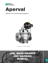
Pressure characteristics during purge and pressurization of a pressurized enclosure using a
MiniPurge® system that incorporates a CLAPS system:
Section 5: Main Components
Air Supply Filter / Regulator
The unit is provided with a 40 μm liquid / dust filter element as a precaution. The user of the MiniPurge®
system must ensure that air supply is to the quality stated in Air Supply Quality paragraph found in the
Installation of the System section. The regulator is factory set to 5 barg (73 psig) and regulates the pressure
of an air supply between 5 and 16 barg (73 to 232 psig). A pressure gauge is fitted down stream of the filter;
this should indicate no less than 5 barg (73 psig). During the purge cycle a pressure drop will be indicated on
the gauge.
Logic Air Supply Regulator
This device provides the system with a stable air supply pressure to the logic system and allows consistent
operation. The pressure level is factory set to 2.5 barg (36 psig) and can be verified by means of the integral
pressure gauge.
Minimum Pressure Sensor
This monitors the pressure inside the pressurized enclosure. When the pressure is below the minimum
required for safe operation, the pressure sensor causes the system to reset and the Alarm / Pressurized
indicator turns Red . The sensor is factory calibrated and set to operate in falling pressure at or above the
minimum specified pressure.
Purge Flow Sensor
The Purge Flow Sensor monitors flow through the Purge Outlet Valve. At correct purge flow rates, above the
minimum specified for purging, the sensor sends a signal that activates the purge timer. This sensor is factory
calibrated to operate on falling flow rate at or above the minimum specified purge flow rate.
Intermediate Pressure
Sensor Pressure
Power Interlock switch
Alarm &Trip
Purge Time Machinery Start Normal Operation
CLAPS Regulator
Pressure
Intermediate switch contacts
open. Intermediate sensor
sends falling pressure signal
Fault Condition - loss of pressure
outside of CLAPS regulation
Minimum Pressure
Sensor Pressure
Purging Pressure
Minimum pressure switch contacts
open. Minimum pressure sensor sends
a low pressure signal.
Alarm indicator shows red (alarm only)
Alarm indicator shows red and power
is disconnected (Alarm and Trip)
Minimum
pressure switch
Intermediate
pressure switch
Power Interlock switch
Alarm Only
Contacts
Active
Inactive

Page
9
ML434 | v36
Expo Technologies UK
T: +44 (0) 20 8398 8011
E: sales@expoworldwide.com
Expo Technologies US
T: +1 (440) 247 5314
Expo Technologies China
T: +86 532 8906 9858
E: qingdao@expoworldwide.com
Intermediate Sensor
This sensor monitors the pressure inside the pressurized enclosure. It senses when the pressure is drops and
provides early warning before the low pressure sensor trips the system. The setting on this is user selectable.
Electronic Purge Timer
When both the enclosure pressure and the purge flow rate are correct, the Purge Flow Sensor activates the
timer and the electronic timer starts. The timing period is selected using switches mounted on the timer
module.
Note: Setting the timer to 00 minutes will cause infinite purging; the cycle will never complete.
During timing, the percentage of the purge cycle is indicated by four LEDs which flashes sequentially while
the timer is running.
The Electronic Timer contains an intrinsically safe battery pack that needs regular replacement. See
Commissioning section.
Purge Complete Valve
This valve receives a signal from the purge timer that indicates the completion of the purge cycle and verifies
that the pressurization signal is still present. If both conditions are satisfied a signal is sent to indicate that the
purge is complete. This performs two functions: to turn on the electrical supply to the pressurized enclosure
and to reduce the high purge flow rate to leakage compensation mode. It also provides a hold-on signal that
maintains the leakage compensation mode with the power switch on, even when the purge timer has reset
ready for the next purge cycle.
OR Gate
This device provides the Purge Complete Valve with the hold-on function referred to previously. When either
the timed-out signal or the purge complete signal is present it allows the pilot signal to be sent to the purge
complete valve.
Alarm Only Circuit (/AO)
If the pressure in the pressurized enclosure is too low the system will normally cut off electrical power to it. In
certain circumstances, where local codes of practice allow, the system can be altered to provide a hold-on
circuit that will maintain the electrical power supply to the pressurized enclosure while also providing a
pressure failure alarm. The user must respond to the alarm and either restore the pressure to the pressurized
enclosure or otherwise make the installation safe; for example, cut off the electrical supply. The decision to
use the Alarm Only facility, and the allowable length of time for non-pressurized operation, is the responsibility
of the user.
Warning: It is potentially dangerous to energise the pressurized enclosure in an non-pressurized
condition when it is known that there is potentially explosive gas or dust in the hazardous location.
LED 1
LED 2LED 3
LED 4 LED 1
LED 2LED 3
LED 4 LED 1
LED 2LED 3
LED 4 LED 1
LED 2LED 3
LED 4
0 to 25%
of purge time 26 to 50%
of purge time 51 to 75%
of purge time 76 to 100%
of purge time

ML434 | v36 Page
10
Expo Technologies UK
T: +44 (0) 20 8398 8011
Expo Technologies US
T: +1 (440) 247 5314
Expo Technologies China
T: +86 532 8906 9858
Visual Indicators
Visual indicators are fitted to provide status information to the operator.
* The Green / Black combination indicates normal operation of the pressurized enclosure after the
initial purging cycle has been completed.
Power Interlock Switch
This flameproof power switch is activated by the signal from the Purge Complete Valve. This activation can
be used to turn on the electrical supply to the pressurized enclosure. The cable from the switch is terminated
in the /PA terminal box.
Alarm / Pressurized Switch
This flameproof switch is operated by the pressurized signal. It allows a remote electrical system status
indicator to show either pressurized or a pressure failure alarm. The cable from the switch is terminated in the
/PA terminal box.
System Purging Switch (Optional)
This switch is operated by the purge flow signal that allows a remote electrical system status indicator to signal
that the system is purging; sometimes referred to as purge in progress. The cable from the switch is
terminated in the /PA terminal box.
Intermediate Switch
This is a flameproof switch which is activated by the signal from the Intermediate Sensor. The cable from the
switch is terminated in the /PA terminal box.
Purge Valve
This changeover valve selects between purge air flow or leakage compensation. It is sized to allow sufficient
air into the enclosure during purging based on: the specified air supply pressure range, the minimum specified
purging outlet flow rate +10% and the expected leakage rate from the pressurized enclosure. At the end of
the purge cycle, the purge valve closes in response to the “Purge Complete” signal; it remains in the closed
position until the next purge cycle is initiated.
Purge Flow Restrictor
This valve restricts the purge flow to the minimum required flow rate. The Purge Flow Restrictor must be
readjusted during commissioning.
Alarm / Pressurized Indicator
Green* Pressurized
Red Pressure Alarm (enclosure pressure low)
System Purging Indicator
Black* Purge flow too low (not in purge mode)
Yellow (flashing) Purging (flow above minimum)

Page
11
ML434 | v36
Expo Technologies UK
T: +44 (0) 20 8398 8011
E: sales@expoworldwide.com
Expo Technologies US
T: +1 (440) 247 5314
Expo Technologies China
T: +86 532 8906 9858
E: qingdao@expoworldwide.com
CLAPS Sensor
This sensor monitors the pressure within the pressurized enclosure and sends a control signal to the CLAPS
Regulator. The normal running pressure must be determined prior to system start-up so that the CLAPS
Sensor may be set to the level required to control the CLAPS Regulator.
CLAPS Regulator
This is the regulator that controls the leakage compensation air flow into the enclosure after the purging is
complete. It either increases or decreases the air flow into the enclosure as appropriate to maintain a stable
running pressure. The CLAPS Regulator must be set at the time of commissioning.
Relief Valve Unit
The Relief Valve Unit allows the purge air to exit the enclosure safely via a built-in spark arrestor. This spark
arrestor is designed to prevent the emission of arcs, sparks and incandescent particles produced within the
pressurized enclosure.
Purge air passes through the Relief Valve Unit; the preset pressure differential across the appropriate orifice
ensures that the purge flow sensor is activated once the selected purge flow has been attained.
During the purge cycle a pneumatic cylinder operates the Purge Outlet Valve that lets the air from inside the
enclosure exhaust through the Relief Valve Unit. When the system changes to leakage compensation mode,
the Purge Outlet Valve is closed and the enclosure sealed.
The Relief Valve Unit has an in-built relief valve. This is sized to ensure that, if the air supply pressure rises
up from the specified maximum, the internal enclosure pressure will not exceed the specified maximum
working pressure of the pressurized enclosure.
/PA Terminal Box
The Terminal Box is increased safety (Ex e) certified and incorporates the terminal connection points for the
alarm and interlock switches. All contacts provided are volt free (dry).
Cable entry methods (for example conduit or cable glands) must be certified to IECEx, ATEX or INMETRO
standards. The main requirement is that IP66 (or better) ingress protection must be provided by use of seals
or washers.
Section 6: Installation of the System
The MiniPurge® is designed for use under normal industrial conditions of ambient temperature, humidity and
vibration. Please consult Expo before installing this equipment in conditions that may cause stresses beyond
normal industrial conditions.The MiniPurge® system must be installed by a competent person in accordance
with relevant standards, such as IEC / EN 60079-14, and any local codes of practice.
The MiniPurge® control unit should be installed either directly on, or close to the pressurized enclosure. It
should be installed such that the system indicators and certification labels are in view.
All parts of the system carry a common serial number. If installing more than one system, ensure that this
commonality is maintained within each system installed.
Relief Valve Unit
To achieve effective purging, the points where air enters and exits the pressurized enclosure should normally
be at opposite ends of the enclosure. The RLV unit must be mounted vertically and there should be a minimum
clearance of 300 mm (12") around the spark arrestor (purge outlet).

ML434 | v36 Page
12
Expo Technologies UK
T: +44 (0) 20 8398 8011
Expo Technologies US
T: +1 (440) 247 5314
Expo Technologies China
T: +86 532 8906 9858
It is important that the interior and exterior of the spark arrestor is kept clean and debris is not allowed
to accumulate; this might affect the calibration of the device. In particular the exterior of the spark arrestor
should not be painted or blocked in any way.
Air Supply Quality
The MiniPurge® system should be connected to a protective gas supply, which is suitable for purging and
pressurization.
The supply pipe connection to the MiniPurge® must be appropriate for the maximum input flow rate for the
application.
The air supply must be regulated at a pressure less than the maximum stated inlet pressure.
The air supply must be: clean, non-flammable and from a non-hazardous location. The air should be of
Instrument Air Quality. Although the purge control system will operate with lower air quality, its operational life
will be adversely affected. The equipment that is being protected by the MiniPurge® may also suffer because
of poor air quality.
With reference to BS ISO 8573-1: 2010, Instrument Air is typically specified as:
Particle Class 1
In each cubic metre of compressed air, the particulate count should not exceed 20,000 particles in the 0.1 to
0.5 micron size range, 400 particles in the 0.5 to 1 micron size range and 10 particles in the 1 to 5 micron size
range.
Humidity or pressure dew point
The dew point, at line pressure, shall be at least 10 °C below the minimum local recorded ambient temperature
at the plant site. In no case, should the dew point at line pressure exceed +3 °C.
Oil Class 2
In each cubic metre of compressed air, not more than 0.1mg of oil is allowed. This is a total level for liquid oil,
oil aerosol and oil vapour.
When an inert gas is being used to supply the purge system, risk of asphyxiation exists. Refer to Application
Suitability section.
Before connection of the air supply to the purge system, the supply pipe work should be flushed through with
instrument quality air to remove any debris that may remain in the pipes. This must be carried out for at least
10 seconds for every meter of supply pipe.
Unless a supply shut-off valve has been fitted to the MiniPurge® system, an external shut-off valve with the
same, or larger, thread size as the Control Unit inlet fitting should be fitted by the installer to prevent any
restriction of purge flow.
The purge air from the MiniPurge® Control Unit should be piped within the pressurized enclosure to ensure
purging of potential dead air spots.
The purge system is fitted with an internal regulator factory set to 3 bar feeding the logic.
Pipe Work
If the MiniPurge® is not connected directly to the pressurized enclosure, pipe work and fittings used to connect
the Control Unit to the pressurized enclosure should be either metallic or appropriate to the environment into
which the system is installed. No valve may be fitted in any signal pipe connecting the Control Unit to the
pressurized enclosure. This pipe work must be fitted in accordance with local codes of practice where
relevant.

Page
13
ML434 | v36
Expo Technologies UK
T: +44 (0) 20 8398 8011
E: sales@expoworldwide.com
Expo Technologies US
T: +1 (440) 247 5314
Expo Technologies China
T: +86 532 8906 9858
E: qingdao@expoworldwide.com
Multiple Enclosures
This system is suitable for the purge and pressurization of the primary pressurized enclosure and its
associated terminal boxes.
Provision and Installation of Alarm Devices
When the pressure inside the pressurized enclosure is above the minimum, the Minimum Pressure Sensor
returns a positive (pressurized) signal causing the alarm indicator on the control unit to change from red to
green.
When the pressure falls below the minimum permissible the positive (pressurized) signal is removed. This
absence of signal indicates a low pressure alarm condition and causes the alarm indicator on the control unit
to go from green to red.
There are volt free (dry) contacts available within the terminal box for remote usage.
The user must make use of this alarm facility in accordance with the local code of practice for Action on Pres-
sure or Flow Failure. Most codes include the following recommendations:
•Zone 1 Installations: Alarm and Automatic Trip of Power.
•Zone 2 Installations: Alarm Only on pressure or flow failure with power being removed manually.
Power Supplies and their Isolation
All power entering the pressurized enclosure should have a means of isolation. This requirement also applies
to any external power sources that are connected to the equipment such as volt-free (dry) contacts within the
pressurized enclosure. This is commonly achieved using the Power Interlock Switch.
Power Interlock Switch
This switch is a Double Pole Normally Open, double-break switch: it provides two independent contacts that
should be connected in series and used to isolate the power. This can be achieved using switchgear or other
suitable switching device. These contacts are terminated and accessible to the user in the Ex e terminal box.
It is the responsibility of the user to ensure that the switch is only operated within appropriate technical limits.
The switch must be replaced after any short circuit that occurs within the main circuit; the switch is a piece of
encapsulated equipment and as such it is not possible to check the state of the contacts. Technical
modifications to the switch are not permitted.
Prior to commissioning, check that the Ex e terminal box is clean, the connections have been made properly,
the cables laid correctly and all screws in the terminals are secure.
In all cases the application and isolation of power must be controlled by the MiniPurge® system using the
power interlock signal.
No switches are permitted between the power switch and the MiniPurge® system other than an authorized
manual override circuit.
The safe use of this switch is the responsibility of the user, all electrical installations must conform to local
codes of practice.
Exception
Power to apparatus that is already suitable for use in hazardous locations need not be isolated by the
MiniPurge® system.

ML434 | v36 Page
14
Expo Technologies UK
T: +44 (0) 20 8398 8011
Expo Technologies US
T: +1 (440) 247 5314
Expo Technologies China
T: +86 532 8906 9858
Section 7: Commissioning
Commissioning the System
Note: The steps 11 and 15 to 21 represent detailed commissioning tests
The following equipment is needed for this process:
• Continuity meter
• Gauge manometer (0 to 200 mbarg)
• Differential manometer
If, after commissioning, the system does not perform as expected, refer to the Fault Finding Section.
Follow the steps as outlined:
1. Check all connections and that the Relief Valve Unit is fitted correctly with an unobstructed path to the
purge exhaust.
2. Close the Purge Flow Restrictor Valve.
3. Fully open external supply shut-off valve where fitted.
4. Check that the internal logic pressure gauge reads 2.5 barg / 36 psi / 250 kPag.
5. Check that the pressure gauge on main air supply reads 5 barg / 73 psi / 500 kPag.
6. Check that the Pressure Relief Valve is correctly set by disconnecting the minimum pressure sensing pipe
at the bulkhead fitting on the input to the MiniPurge®. This will disable all of the pressure sensors.
• Using a 4 mm nylon tube, connect a manometer to the bulkhead fitting from which the minimum
pressure sensing pipe was removed.
• Open the Purge Flow Restrictor Valve very slowly, until the Pressure Relief Valve opens
• Check the opening pressure is within calibration limits.
• This test can be carried out several times to ensure repeatability and compliance.
Refer to the Maintenance of the System section if the Relief Valve needs recalibrating.
7. Close the Purge Flow Restrictor Valve.
8. Remove the manometer and reconnect the minimum pressure sensing pipe to the bulkhead fitting.
9. Remove red plug from the top of the Minimum Pressure Sensor and connect a gauge manometer.
10.Connect a differential manometer to the test points on the flow sensor.
11.To check sensor calibration
• The internal pressure in the pressurized enclosure must be below Relief Valve lift off pressure and
above the CLAPS pressure
• At this time the pressurized indicator should be green.
• gradually open Purge Flow Restrictor Valve until purging indicator flashes yellow.
Note: For large volumes it may take a long time for the purge flow to start.
• very slowly close Purge Flow Restrictor Valve until the purging indicator stops flashing yellow.
• Take a reading from pressure gauge.
12.To set the purge flow rate:
• Turn on the compressed air to the MiniPurge®.
• Gradually open the Purge Flow Restrictor Valve until the black / yellow indicator changes to yellow
(flashing).
• The flashing yellow indicator confirms the correct flow rate.
• The differential pressure should be greater than 6.4 mbarg.

Page
15
ML434 | v36
Expo Technologies UK
T: +44 (0) 20 8398 8011
E: sales@expoworldwide.com
Expo Technologies US
T: +1 (440) 247 5314
Expo Technologies China
T: +86 532 8906 9858
E: qingdao@expoworldwide.com
• The relief valve is supplied with different orifice plates for the specified flow rate. This orifice
plate is held in position by two M3 screws and can easily be changed by removing the large cover plate
from over the outlet valve assembly and screws.
Warning: When opening the Purge Flow Restrictor Valve, ensure the over pressure within the pres-
surized enclosure does not exceed the pressure relief valve setting.
13.The purge timer will start as soon as the Purging Indicator flashes yellow. Check that the time delay
between the indicator turning to yellow (flashing) and returning to black is not less than the minimum
time required for complete purging of the pressurized enclosure. Times in excess of minimum are
permitted.
14.After the purge has been completed, the Purge Valve will close and the air flow into the pressurized
enclosure will be controlled by the CLAPS Regulator. The initial setting may be too high or too low.
15.Gradually turn the CLAPS Regulator anti-clockwise to reduce enclosure pressure.
16.Reduce regulator until intermediate sensor causes contacts to open.
17.Check the manometer on the minimum pressure sensor.
18.Continue to reduce the CLAPS Regulator to test the minimum pressure sensor.
19.To check operation of Minimum Pressure Sensor, check readings on manometer as system will
automatically re-purge when it reaches minimum pressure.
20.While the system re-purges, return the CLAPS Regulator to the initial setting.
21.If minimum pressure is below the set point, refer to the Recalibration section
22.If the setting is too high, continual rising and falling of the enclosure pressure will be seen as the CLAPS
Regulator automatically shuts off and reinstates the flow. The CLAPS Regulator should be adjusted to
reduce the flow into the pressurized enclosure by turning the adjuster screw anti-clockwise.
23.If the initial setting is too low the CLAPS Regulator may not provide enough air flow causing a gradual
decline in enclosure pressure. To increase the flow into the pressurized enclosure, adjust the CLAPS
Regulator Relief Valve unit by turning the adjuster screw clockwise.
24.To test the CLAPS settings, create a leak in the system by removing a bolt or losening a gland plate in
order to create a 15mm hole. Remember to replace bolt or retighten gland plate after testing.
25.The setting of the CLAPS Sensor is factory calibrated to the normal working pressure expected in the
pressurized enclosure, typically 10 mbarg. The pressure in the pressurized enclosure should be
stabilized as close as possible to this figure. This can be checked by a manometer attached to the
minimum pressure sensor.
26.Remove the air supply to the system, remove all test equipment and replace all plugs.
Normal Operation
For normal operation of the system, after commissioning has been carried out it is possible to turn the air
supply valve on or off to start or stop the system. After this, the purge and pressurization sequence is
automatic.

ML434 | v36 Page
16
Expo Technologies UK
T: +44 (0) 20 8398 8011
Expo Technologies US
T: +1 (440) 247 5314
Expo Technologies China
T: +86 532 8906 9858
Section 8: Maintenance of the System
General maintenance
The maintenance of the system outlined in this manual should be supplemented with any additional
requirements set out in appropriate local codes of practice.
The following checks should be carried out every 6 – 36 months dependent on environment according
to IEC / EN 60079-17
• Tests outlined in the Detailed Commissioning section.
• Ensure that the Relief Valve Unit is free from contamination prior to making any adjustment. To do this:
• Remove large cover plate using a 8 mm spanner (wrench).
• Check that the interior and all components are clean and free from contamination.
• Replace large cover plate.
• Check the condition of the air supply filter element. Clean or replace as necessary.
Additional maintenance checks
The following additional checks are recommended at least every 3 years:
Check that:
• Apparatus is suitable for use in the hazardous location.
• There are no unauthorised modifications.
• The air supply is uncontaminated.
• The interlocks and alarms function correctly.
• Approval labels are legible and undamaged.
• Adequate spares are carried.
• The action on pressure failure is correct.
Maintenance of Electronic Timer
This should be carried out every 3 years.
• The intrinsically safe battery pack associated with the electronic timer should be replaced and the
commissioning tests repeated.
• After the timing phase has elapsed, the battery may be hot-swapped in the hazardous location without
affecting the operation of the MiniPurge® system
Re-calibration of the Relief Valve Unit
Warning
Incorrect adjustment of the Relief Valve Unit can lead to significant over pressure and result in
damage to the enclosure.
If maximum pressure setting is reached, stop adjustment and reduce the pressure.
To perform the following adjustments, an 8 mm spanner (wrench) and a 2.5 mm hex key will be required.
Ensure that the Relief Valve Unit is free from contamination prior to making any adjustment. To do this:
• Remove large cover plate using a 8 mm spanner (wrench).
• Check that the interior and all components are clean and free from contamination.
• Replace large cover plate
To adjust the lift off pressure of the Relief Valve:
• Attach test equipment as described in the Commissioning Section.

Page
17
ML434 | v36
Expo Technologies UK
T: +44 (0) 20 8398 8011
E: sales@expoworldwide.com
Expo Technologies US
T: +1 (440) 247 5314
Expo Technologies China
T: +86 532 8906 9858
E: qingdao@expoworldwide.com
• Remove small cover plate.
• Whilst holding the central adjustment screw in position using the hex key, loosen the retaining nut.
• Adjust the hex key clockwise to increase, or anti-clockwise to reduce the lift off pressure.
• Before testing, retighten the locking nut whilst holding the adjustment screw in place.
• Carry out the commissioning tests to check the correct setting of the relief valve after adjustment.
• The adjustment is sensitive and it is recommended that a 1/4 turn (maximum) adjustments are applied
between tests.
Re-calibration of the Pressure Sensors
The brass nozzle on the sensor is sealed into position using Loctite thread sealant. If the thread has seized
up, remove to a safe area and heat slightly to soften prior to making any adjustment. This prevents potential
damage to the brass of the nozzle.
• Disconnect pipe work from the sensor, including pipe located below the sensor.
• Remove sensor by unscrewing anti-clockwise.
• The nozzle is located under the sensor.
• The adjustment is sensitive, turn the nozzle in 1/8 of a turn steps.
• Turn clockwise to reduce the pressure setting and anti-clockwise to increase.
• Replace sensor, screwing clockwise.
• Reconnect all pipe work.
Orifice Plate
Allen Screw and Lock NUT
Removing the small cover plate
to set the RLV opening pressure
/