
Single Stage - Direct Vent (Sealed Combustion)
Forced Air
For Installation in:
• Manufactured Homes
• Modular Homes / Buildings
• Park Models, & Manufactured Buildings
MG2R Series Downflow Condensing Gas Furnace 95% AFUE
CAUTION
HUD Manufactured Home Construction and
Safety Standards (3280.714) prohibit the use
of noncertified air conditioning or heat pump
equipment with this furnace. It is strongly
recommended that manufactured housing
air conditioning components from Nortek
Global HVAC be selected to provide a matched
system specifically designed to meet these
requirements.
The cutting, splicing or modifying of any
internal electrical wiring may void product
warranties and create a hazardous condition.
Failure to comply with these standards could
also provide inadequate heating or cooling
performance and cause structural damage to
a manufactured home.
Please contact your local distributor for help.
A directory of Nortek Global HVAC factory
authorized servicers is located in the furnace
homeowner packet.
Reference: HUD Manufactured Home
Construction and Safety Standards 3280.714.
INSTALLATION INSTRUCTIONS
WARNING AVERTISSEMENT
FIRE OR EXPLOSION HAZARD
• Failure to follow safety warnings exactly could
result in serious injury, death or property
damage.
• Installation and service must be performed
by a qualified installer, service agency or the
gas supplier.
• Do not store or use gasoline or other
flammable vapors and liquids in the vicinity
of this or any other appliance.
WHAT TO DO IF YOU SMELL GAS
• Do not try to light any appliance.
• Do not touch any electrical switch; do not
use any phone in your building.
• Leave the building immediately.
• Immediately call your gas supplier from a
neighbors phone. Follow the gas suppliers
instructions.
• If you cannot reach your gas supplier, call
the fire department.
RISQUE D’INCENDIE OU D’EXPLOSION
• Le non-respect des avertissements de sécurité
pourrait entraîner des blessures graves ou des
dommages matériels.
• L’installation et l’entretien doivent être effectués
par un installateur qualifié, un organisme de
service ou le fournisseur de gaz.
• Ne pas entreposer ni utiliser de l’essence ni
d’autres vapeurs ou liquides inflammables
dans le voisinage de cet appareil, ni de tout
autre appareil.
QUE FAIRE S’IL Y A UNE ODEUR DE GAZ
• Ne tenter d’allumer aucun appareil.
• Ne toucher à aucun interrupteur électrique;
n’utiliser aucun téléphone dans le bâtiment.
• Évacuer l’immeuble immédiatement.
• Appeler immédiatement le fournisseur de gaz en
employant le téléphone d’un voisin. Respecter
les instructions du fournisseur de gaz.
• Si personne ne répond, appeler le service des
incendies.
DO NOT DESTROY. PLEASE READ CAREFULLY & KEEP IN A SAFE PLACE FOR FUTURE REFERENCE.
NE PAS DÉTRUIRE. VEUILLEZ LIRE ATTENTIVEMENT ET CONSERVER EN UN LIEU SÛR POUR RÉFÉRENCE ULTÉRIEURE.
Front Return
without
Coil Box
Top Return
without
Coil Box
Front Return
with Coil Box
Top Return
with Coil Box

2
IMPORTANT SAFETY INFORMATION ..................... 3
GENERAL INFORMATION ........................................ 4
Requirements & Codes .......................................... 4
Clearances to Combustible Materials ..................... 5
Combustion Air Quality ........................................... 5
Heating Load .......................................................... 5
Condensate Disposal ............................................. 5
COMBUSTION AIR & VENTING REQUIREMENTS 6
Important Information ............................................. 7
Category IV Appliances .......................................... 7
Direct Vent Installation ............................................ 7
Vent Pipe Length & Diameter ............................... 7
Vent Pipe Material ................................................ 8
Vent Pipe Installation ............................................ 8
Outdoor Terminations - Horizontal Venting .......... 8
Outdoor Terminations - Vertical Venting .............. 9
CIRCULATING AIR REQUIREMENTS ...................... 10
Vent Freezing Protection ...................................... 10
Existing Installations ............................................. 10
Ventilaire III or IV Air Quality Package ................... 10
Plenums & Air Ducts ............................................... 11
Supply Air Connections .......................................... 11
Return Air Connections .......................................... 11
Closet & Alcove Installations .................................. 11
Furnace Filter ......................................................... 12
Dampers ................................................................. 13
Acoustical Treatments ............................................ 13
FURNACE INSTALLATION ....................................... 13
About The Furnace ................................................. 13
Before You Install this Furnace .............................. 13
Locating the Unit ..................................................... 14
Locating & Cutting Floor Openings ...................... 14
Locating & Cutting Ceiling Openings .................... 15
Installing Finger Tabbed Duct Connectors ............. 15
Narrow Duct Attachment - Option 1 ..................... 15
Narrow Duct Attachment - Option 2 ..................... 16
Installing Screw-Down Duct Connectors ................ 16
Round Duct Connector Installation ......................... 16
Installing the Furnace ............................................. 16
Condensate Drainage ............................................. 17
GAS SUPPLY & PIPING ............................................ 18
Leak Check ............................................................. 19
High Altitude Application ......................................... 19
Converting to LP/Propane Gas at Altitudes
between 0 & 10,000 FT. ......................................... 20
Removing The Burner Orifices ............................. 20
Gas Pressure Verification ....................................... 21
Measuring the Supply Gas Pressure .................... 21
Lighting & Adjustment of the Appliance ................ 21
Measuring the Manifold Pressure ......................... 21
Removing the Manometer/Pressure Gauge ......... 22
Completing the Conversion .................................... 22
TABLE OF CONTENTS
ELECTRICAL WIRING .............................................. 22
Line Voltage Wiring ................................................ 22
Thermostat / Low Voltage Connections .................. 23
Heat Anticipator .................................................... 23
Grounding ............................................................... 24
START-UP & ADJUSTMENTS .................................. 24
Pre-Start Check List ............................................... 24
Start-up Procedures ............................................... 24
Verifying Input Rate ................................................ 24
Verifying & Adjusting Temperature Rise ................. 24
Verifying Burner Operation ..................................... 25
Verifying Operation of the Supply Air Limit Switch . 25
OPERATING SEQUENCE ......................................... 25
Heating Cycle ......................................................... 25
Cooling Cycle ......................................................... 25
Fan Mode ............................................................... 25
MAINTENANCE ......................................................... 26
Air Filter(s) .............................................................. 26
Blower Compartment .............................................. 26
Cleaning of Burners ................................................ 26
Vent System ........................................................... 27
Heat Exchanger & Burner Maintenance ................. 27
Lubrication .............................................................. 27
TROUBLESHOOTING ............................................... 27
DESCRIPTION OF COMPONENTS .......................... 28
FIGURES & TABLES ................................................. 29
Cabinet Dimensions ............................................... 29
Figure 24. Front Return Cabinets (Without
Coil Box) .............................................. 29
Figure 25. Front Return Cabinets (With
Coil Box) .............................................. 30
Figure 26. Top Return Cabinets
(Without Coil Box) ............................... 31
Figure 27. Top Return Cabinets (With Coil Box) .. 32
Electrical Information .............................................. 33
Figure 28. MG2R Wiring Diagram ........................ 33
Figure 29. MG2R Ladder Diagram ....................... 34
Gas Information ...................................................... 35
Table 7. Gas Flow Rates ...................................... 35
Table 8. Gas Pipe Capacities ............................... 35
Table 9. Orifices for Propane Gas ........................ 36
Table 10. Natural Gas Heating Values ................. 36
Table 11. Orifices for Natural Gas High
Heating Value ....................................... 36
Table 12. Orifices for Natural Gas Low
Heating Value ....................................... 36
Venting Information ................................................ 37
Table 13. Vent Termination Clearances ............... 37
Figure 30. Horizontal / Vertical Venting &
Clearances from Soffit ......................... 38
INSTALLATION CHECKLIST .................................... 40

3
IMPORTANT SAFETY INFORMATION
INSTALLER: Please read all instructions before servicing
this equipment. Pay attention to all safety warnings and
any other special notes highlighted in the manual. Safety
markings are used frequently throughout this manual to
designate a degree or level of seriousness and should
not be ignored.
WARNING indicates a potentially hazardous situation that
if not avoided, could result in personal injury or death.
CAUTION indicates a potentially hazardous situation that
if not avoided, may result in minor or moderate injury or
property damage.
• To minimize equipment failure or personal injury, it is
essential that only qualified individuals install, service, or
maintain this equipment. If you do not posses mechanical
skills or tools, call your local dealer for assistance.
• Follow all precautions in the literature, on tags, and
on labels provided with the equipment. Read and
thoroughly understand the instructions provided with
the equipment prior to performing the installation and
operational checkout of the equipment.
• Use caution when handling this appliance or removing
components. Personal injury can occur from sharp metal
edges present in all sheet metal constructed equipment.
• Do not store any of the following on, or in contact with,
the unit: Rags, brooms, vacuum cleaners, or other
cleaning tools, spray or aerosol cans, soap powders,
bleaches, waxes, cleaning compounds, plastics or
plastic containers, paper bags or other paper products,
gasoline, kerosene, cigarette lighter fluid, dry cleaning
fluids, paint thinners, or other volatile fluids.
• Installation of equipment may require brazing operations.
Installer must comply with safety codes and wear
appropriate safety equipment (safety glasses, work
gloves, fire extinguisher, etc.) when performing brazing
operations.
• The installer should become familiar with the units wiring
diagram before making any electrical connections to the
unit. See the unit wiring label, Figure 28 (page 33) or
Figure 29 (page 34).
• Always reinstall the doors on the indoor blower after
servicing or cleaning/changing the filters. Do not operate
the indoor blower without all doors and covers in place.
WARNING:
The safety information listed in this manual must
be followed during the installation, service, and
operation of this unit. Unqualified individuals
should not attempt to interpret these instructions
or install this equipment. Failure to follow safety
recommendations could result in possible
damage to the equipment, serious personal
injury or death.
WARNING:
ELECTRICAL SHOCK, FIRE OR
EXPLOSION HAZARD
Failure to follow safety warnings exactly could
result in serious injury, death or property damage.
Improper servicing could result in dangerous
operation, serious injury, death or property
damage.
• Before servicing, disconnect all electrical power
to the indoor blower.
• When servicing controls, label all wires prior
to disconnecting. Reconnect wires correctly.
• Verify proper operation after servicing.
WARNING:
FIRE OR EXPLOSION HAZARD
• Failure to follow safety warnings exactly could
result in serious injury, death or property
damage.
• Installation and service must be performed by
a qualified installer, service agency or the gas
supplier.
• Do not store or use gasoline or other flammable
vapors and liquids in the vicinity of this or any
other appliance.
\
WHAT TO DO IF YOU SMELL GAS
• Do not try to light any appliance.
• Do not touch any electrical switch; do not use
any phone in your building.
• Leave the building immediately.
• Immediately call your gas supplier from a
neighbor’s phone. Follow the gas supplier’s
instructions.
• If you cannot reach your gas supplier, call the
fire department.
WARNING:
Improper installation, service, adjustment, or
maintenance may cause explosion, fire, electrical
shock or other hazardous conditions which may
result in personal injury or property damage.
Unless otherwise noted in these instructions,
only factory authorized kits or accessories may
be used with this product.

4
GENERAL INFORMATION
Requirements & Codes
WARNING:
This unit must be installed in accordance
with instructions outlined in this manual
during the installation, service, and operation
of this unit. Unqualified individuals should
not attempt to interpret these instructions or
install this equipment. Failure to follow safety
recommendations could result in possible
damage to the equipment, serious personal
injury or death.
• The installer must comply with all local codes and
regulations which govern the installation of this type
of equipment. Local codes and regulations take
precedence over any recommendations contained in
these instructions. Consult local building codes and
the National Electrical Code (NFPA 70) for special
installation requirements.
• All electrical wiring must be completed in accordance
with local, state and national codes and regulations and
with the National Electric Code (NFPA 70) or in Canada
the Canadian Electric Code Part 1 CSA C.22.1.
• This furnace must be installed in accordance with
these instructions, all applicable local building codes
and the current revision of the National Fuel Gas Code
(NFPA54/ANSI Z223.1) or the Natural Gas and Propane
Installation Code, CAN/CGA B149.1.
• Use only with type of gas approved for this furnace.
Refer to the furnace rating plate.
• Install this furnace only in a location and position as
specified on page 5.
• Provide adequate combustion and ventilation air to the
furnace space as specified on pages 6 - 7.
• Provide adequate clearances around the vent air intake
terminal as specified in Figure 1, Figure 2, Figure 3, and
Figure 4 (page 9).
• Combustion products must be discharged outdoors.
Connect this furnace to an approved vent system only,
as specified on pages 7 - 10.
• Never test for gas leaks with an open flame. Use
a commercially available soap solution to check all
connections. See page 19.
• This furnace is designed to operate with a maximum
external pressure rise of 0.3 inches of water column.
Consult the rating plate for the proper circulating air
flow and temperature rise. It is important that the duct
system be designed to provide the correct flow rates
and external pressure rise. An improperly designed duct
system can result in nuisance shutdowns, and comfort
or noise issues.
• This furnace must not be used for temporary heating
of buildings or structures under construction.
• The Commonwealth of Massachusetts requires
compliance with regulation 248 CMR 4.00 and 5.00 for
installation of through – the – wall vented gas appliances
as follows:
1. For direct-vent appliances, mechanical-vent heating
appliances or domestic hot water equipment, where the
bottom of the vent terminal and the air intake is installed
below four feet above grade the following requirements
must be satisfied:
a.) A carbon monoxide (CO) detector and alarm shall be
placed on each floor level where there are bedrooms.
The detector shall comply with NFPA 720 (2005
Edition) and be mounted in the living area outside
the bedroom(s).
b.) A (CO) detector shall be located in the room that
houses the appliance or equipment and shall:
• Be powered by the same electrical circuit as the
appliance or equipment. Only one service switch
shall power the appliance and the (CO) detector;
• Have battery back-up power;
• Meet ANSI/UL 2034 Standards and comply with
NFPA 720 (2005 Edition); and Approved and listed
by a Nationally Recognized Testing Laboratory as
recognized under 527 CMR.
c.) A Product-approved vent terminal must be used, and
if applicable, a product-approved air intake must be
used. Installation shall be in strict compliance with the
manufacturer’s instructions. A copy of the installation
instructions shall remain with the appliance or
equipment at the completion of the installation.
d.) A metal or plastic identification plate shall be mounted
at the exterior of the building, 4 feet directly above
the location of vent terminal. The plate shall be of
sufficient size, easily read from a distance of eight
feet away, and read “Gas Vent Directly Below”.
2. For direct-vent appliances, mechanical vent heating
appliances or domestic hot water equipment where the
bottom of the vent terminal and the air intake is installed
above four feet above grade the following requirements
must be satisfied:
a.) A (CO) detector and alarm shall be placed on each
floor level where there are bedrooms. The detector
shall comply with NFPA 720 (2005 Edition) and be
mounted in the living area outside the bedroom(s).
b.) The (CO) detector shall:
• Be located in the room that houses the appliance or
equipment;
• Be hard-wired, battery powered or both.
• Shall comply with NFPA 720 (2005 Edition).
c.) A product-approved vent terminal must be used, and
if applicable, a product-approved air intake must be
used. Installation shall be in strict compliance with the
manufacturer’s instructions. A copy of the installation
instructions shall remain with the appliance or
equipment at the completion of the installation.

5
Clearances to Combustible Materials
This furnace is Design Certified in the U.S. and Canada
for the minimum clearances to combustible materials.
NOTE: The furnace is listed for installation on combustible
or non-combustible flooring. However, wood is the only
combustible flooring allowed for installation. To obtain
furnace base model number and specific clearance
information, refer to the furnace rating plate, located inside
of the furnace cabinet.
Access for positioning and servicing the unit must be
considered when locating the unit. The need to provide
clearance for access to panels or doors may require
clearance distances over and above the requirements.
Allow 18 inches minimum clearance from the front of
the unit. However 36 inches is strongly recommended.
See Table 1 for minimum clearance requirements.
The ductwork should be appropriately sized to the capacity
of the furnace to ensure its proper airflow rating. For
installations above 2,000 ft., the furnace should have a
sea level input rating large enough that it will meet the
heating load after deration for altitude.
Combustion Air Quality
CAUTION:
Combustion air must not be drawn from a
corrosive atmosphere.
To maximize heat exchanger life, the combustion air
must be free of chemicals that can form corrosive acidic
compounds in the combustion gases. The required source
of combustion air is to use outdoor air.
If outside air is used as return air to the furnace for
ventilation or to improve indoor air quality, the system must
be designed so that the return air is not less than 60° F
(15° C) during operation. If a combination of indoor and
outdoor air is used, the ducts and damper system must
be designed so that the return air supply to the furnace is
equal to the return air supply under normal, indoor return
air applications.
Exposure to the following substances in the combustion
air supply will result in safety and performance related
problems. The list below contains examples of chemical
containments found in a wide variety of common
commercial household products:
Permanent wave solutions
Chlorinated waxes and cleaners
Chlorine based swimming pool chemicals
Water softening chemicals
De-icing salts or chemicals
Carbon Tetrachloride
Halogen type refrigerants
Cleaning solvents (perchloroethylene)
Printing inks, paint removers, varnishes, etc.
Hydrochloric Acid
Cements and glues
Antistatic fabric softeners
Masonry acid washing materials
Heating Load
This furnace should be sized to provide the design heating
load requirement. Heating load estimates can be made
using approved methods available from Air Conditioning
Contractors of America (Manual J); American Society of
Heating, Refrigerating, and Air Conditioning Engineers;
or other approved engineering methods. Excessive
oversizing of the furnace could cause the furnace
and/or vent to fail prematurely.
Condensate Disposal
The method for disposing of condensate varies according
to local codes. Consult your local code or authority having
jurisdiction. Neutralizer kit P/N 902377 is available for
use with this furnace. Please follow the instructions
provided with the kit.
INSTALLATION CLEARANCES
CLOSET ALCOVE
Front * 1" 1"
Rear 0" 0"
Sides 0" 0"
Top 6" 6"
Duct w/in 3ft of furnace 1/4" 1/4"
Vent 0” 0”
Plenum Without Coil Box 1" 1"
Plenum With Coil Box 0” 0”
NOTES:
Alcove Installations - Allow 18 in. minimum clearance from front of unit
to nearest wall or partition for servicing.
Closet installations - Require a return air grill installed in the door or a
partially louvered door across the opening for proper air circulation. For
clearances 6” or greater, the closet must have an open free area of 235
in
2
minimum. For special clearances between 1” & 6”, requirements are
a louvered door with a minimum of 250 in
2
(1613 cm
2
) free area. For 1”
clearance from furnace, use a fully louvered door with at least 400 in
2
of
free airflow area. A fully louvered closet door is strongly recommended
for all installation types.
LEFT
SIDE
FRONT
RIGHT
SIDE
REAR
RIGHT
SIDE
MODELS WITH FRONT AIR RETURN MODELS WITH TOP AIR RETURN
REAR
LEFT
SIDE
FRONT
VENT
VENT
Table 1. Minimum Clearances

6
COMBUSTION AIR & VENTING REQUIREMENTS
WARNING:
CARBON MONOXIDE POISONING HAZARD
Failure to follow the steps outlined below for
each appliance connected to the venting system
being placed into operation could result in carbon
monoxide poisoning or death. The following steps
shall be followed with each individual appliance
connected to the venting system being placed in
operation, while all other appliances connected
to the venting system are not in operation:
1. Seal any unused openings in the venting
system.
2. Inspect the venting system for proper size and
horizontal pitch, as required in the National Fuel
Gas Code, ANSI Z223.1/NFPA 54 or the CSA
B149.1, Natural Gas and Propane Installation
Codes and these instructions. Determine that
there is no blockage or restriction, leakage,
corrosion and other deficiencies which could
cause an unsafe condition.
3. As far as practical, close all building doors
and windows and all doors between the space
in which the appliance(s) connected to the
venting system are located and other spaces
of the building.
4. Close fireplace dampers.
5. Turn on clothes dryers and any appliance not
connected to the venting system. Turn on
any exhaust fans, such as range hoods and
bathroom exhausts, so they are operating at
maximum speed. Do not operate a summer
exhaust fan.
6. Follow the lighting instructions. Place the
appliance being inspected into operation.
Adjust the thermostat so appliance is operating
continuously.
7. Test for spillage from draft hood equipped
appliances at the draft hood relief opening
after 5 minutes of main burner operation. Use
the flame of a match or candle.
8. If improper venting is observed during any of
the above tests, the venting system must be
corrected in accordance with the National Fuel
Gas Code, ANSI Z223.1/NFPA 54 and/or CSA
B149.1, Natural Gas and Propane Installation
Codes.
9. After it has been determined that each appliance
connected to the venting system properly vents
when tested as outlined above, return doors,
windows, exhaust fans, fireplace dampers and
any other gas-fired burning appliance to their
previous conditions of use.
AVERTISSEMENT:
RISQUE D’EMPOISONNEMENT AU
MONOXYDE DE CARBONED
Le non-respect des consignes suivantes portant
sur chacun des appareils raccordés au système
d’évacuation mis en service pourrait entraîner
l’empoisennement au monoxyde de carbone ou la mort.
Les consignes suivantes doivent être observées pour
chaque appareil raccordé au système d’évacuation
mis en service si les autres appareils raccordés au
système ne sont pas en service:
1. Sceller toute ouverture non utilisée de la systéme
d’évacuation;
2. S’assurer que la systéme d’évacuation présente
des dimensions et une pente horizontale
conformes à la norme ANSI Z223.1/NFPA
54, intitulée National Fuel Gas Code ou aux
codes d’installation CSA-B149.1, ainsi qu’aux
présentes instructions. S’assurer que la systéme
d’évacuation n’est pas bloquée, restreinte,
corrodée, qu’elle ne fuit pas et qu’elle ne présente
aucun autre défaut potentiellement dangereux;
3. Dans la mesure du possible, fermer toutes les
portes et fenêtres du bâtiment, et toutes les portes
entre la pièce où se trouve l’appareil raccordé à
la systéme d’évacuation et les autres pièces du
bâtiment.
4. Fermer les registres des foyers;
5. Mettre en service les sécheuses et tout autre
appareil qui n’est pas raccordé à la systéme
d’évacuation. Faire fonctionner à régime maximal
tout ventilateur d’évacuation, tel que les hottes de
cuisinière et les ventilateurs de salles de bains.
Ne pas mettre en service les ventilateurs d’été.
6. Respecter les instructions d’allumage. Mettre en
service l’appareil à l’essai. Régler le thermostat
de manière à ce que l’appareil fonctionne sans
interruption;
7. Vérifier s’il y a débordement à l’orifice d’évacuation
du coupe tirage des appareils dotés d’un coupe
tirage 5 minutes après l’allumage du brûleur
principal. Utiliser la flamme d’une allumette ou
d’une chandelle.
8. Si l’on constate, au cours de l’un des essais
qui précèdent, que l’évacuation est déficiente,
corriger le système d’évacuation conformément
à la norm ANSI Z223.1/NFPA 54, National Fuel
Gas Code, et (ou) aux codes d’installation CSA
B149.1.
9. Après avoir déterminé que tous les appareils
raccordés à la systéme d’évacuation évacuent
correctement tel que prescrit ci-dessus,
rouvrir les portes et les fenêtres et remettre les
ventilateurs d’évacuation, les registres de foyers
et tout autre appareil fonctionnant au gaz à leur
état de fonctionnement initial.

7
Direct Vent Installation
This condensing furnace is certified for installation as
a Direct Vent (2-pipe) appliance. Direct Vent (2-pipe)
furnaces draw combustion air directly from the outdoors
and then vent the combustion products back outside,
isolating the entire system from the indoor space. It is
important to make sure that the whole system is sealed
and clearances to combustibles are maintained regardless
of the installation being in a confined or unconfined space.
This section specifies installation requirements for Direct
Vent (2-pipe) piping. Table 2, (page 8) contains the
length of vent and combustion air piping for this type of
installation.
Provisions must be made during the installation of this
furnace that provide an adequate supply of fresh air for
combustion and ventilation. The combustion air from the
outside needs to be clear of chemicals that can cause
corrosion. The inlet pipe should not be placed near
corrosive chemicals such as those listed on page 5.
Air openings on top of the furnace and openings in closet
doors or walls must never be restricted. If the furnace is
operated without adequate air for combustion, the flame
roll-out switch will open, turning off the gas supply to the
burners. This safety device is a manually reset switch.
DO NOT install jumper wires across these switches
to defeat their function or reset a switch without
identifying and correcting the fault condition. If a
switch must be replaced, use only the correct sized part
specified in the Replacement Parts List provided online.
Vent Pipe Length & Diameter
For proper furnace operation, the combustion air and vent
piping must not be excessively restrictive.
• The venting system should be designed to have the
minimum number of elbows or turns.
• All horizontal runs must slope upwards from the furnace
at 1/4 inch minimum per running foot of vent.
• Transition to the final vent diameter should be done as
close to the furnace outlet as practical.
• Always use the same size or a larger pipe for combustion
air that is used for the exhaust vent.
Table 2 indicates the maximum allowable pipe length for
a furnace of known input rate, when installed with piping
of selected diameter and number of elbows. To use the
table, the furnace input rate, the centerline length and the
number of elbows on each pipe must be known.
When estimating the length of vent runs, consideration
must be made to the effect of elbows and other fittings.
This is conveniently handled using the idea of “equivalent
length”. This means the fittings are assigned a linear length
that accounts for the pressure drop they will cause. For
example: a 3” diameter, long radius elbow is worth the
equivalent of 3.5 feet of linear run.
The equivalent lenghts of tees and various elbows are
listed in Table 2. Measure the linear length of your vent run
and then add in the equivalent length of each fitting. The
total length, including the equivalent fitting lengths, must
be less than the maximum length specified in the table.
Important Information
WARNING:
Furnace installation using methods other than
those described in the following sections must
comply with the National Fuel Gas Code (NFGC)
and all applicable local codes.
WARNING:
Upon completion of the furnace installation,
carefully inspect the entire flue system both
inside and outside the furnace to assure it is
properly sealed. Leaks in the flue system can
result in serious personal injury or death due
to exposure of flue products, including carbon
monoxide.
WARNING:
This furnace must not be vented with other
appliances, even if that appliance is of the
condensing type. This includes water heaters
of any efficiency. Common venting can result
in severe corrosion of other appliances or their
venting and can allow combustion gases to
escape through such appliances or vents. Do
not vent the furnace to a fireplace chimney or
building chase.
• This furnace must be vented in compliance with
the current revision of the National Fuel Gas Code
(ANSI-Z223.1/NFPA54). Instructions for determining
the adequacy of combustion air for an installation
can be found in the current revision of the NFGC
(ANSI Z223.1 / NFPA54). Consult local codes for
special requirements. These requirements are for US
installations as found in the NFGC.
• The requirements in Canada (B149.1) are structured
differently. In Canada, venting shall conform to the
requirements of the current (CAN/CGA B149.1 or .2)
installation codes. Consult local codes for special
requirements.
Category IV Appliances
This furnace is classified as a Category IV appliance,
which requires special venting materials and installation
procedures.
Category IV appliances operate with positive
vent pressure and requires thoroughly sealed vent
systems. They also produce liquid condensate, which is
slightly acidic and can cause severe corrosion of ordinary
venting materials. Furnace operation can be adversely
affected by restrictive vent and combustion air piping.

8
MAXIMUM DIRECT VENT, DUAL PIPE LENGTH (FT.)
MG2R INPUTS
(BTU)
INLET / OUTLET
2” DIAMETER
INLET / OUTLET
3” DIAMETER
45,000 30 60
60,000 30 60
72,000 30 60
†
NOTES:
1. Subtract 2.5 ft. for each additional 2 inch long radius elbow, subtract
5ft for each additional 2” short radiious elbow, subtract 3.5 ft. for each
additional 3 inch long radius elbow, and 7 ft. for each additional 3
inch short radius elbow.
2. Two 45 degree elbows are equivalent to one 90 degree elbow.
3. This table applies for elevations from sea level to 2,000 ft. For higher
elevations, decrease pipe lengths by 8% per 1,000 ft of altitude.
Table 2. Vent Pipe Lengths
• The quality of outdoor air must also be considered. Be
sure that the combustion air intake is not located near
a source of solvent fumes or other chemicals which
can cause corrosion of the furnace combustion system.
(See page 5 for a sample list of substances).
• Route piping as direct as possible between the furnace
and the outdoors. Longer vent runs require larger
diameters. Vent piping must be sloped upwards 1/4”
per foot in the direction from the furnace to the terminal.
This ensures that any condensate flows back to the
condensate disposal system.
• When a 2-pipe system is used, the combustion air
intake and the vent exhaust must be located in the
same atmospheric pressure zone. This means both
pipes must exit the building through the same portion
of exterior wall or roof as shown in Figure 1, Figure 2
& Figure 4 (page 9) and Figure 30 (page 38).
• Piping must be mechanically supported so that its weight
does not bear on the furnace. Pipe supports must be
installed a minimum of every five feet along the vent run to
ensure no displacement after installation. Supports may
be at shorter intervals if necessary to ensure that there
are no sagging sections that can trap condensate. It is
recommended to install couplings (Figure 30) along the
vent pipe, on either side of the exterior wall. Couplings
may be required by local code.
• If breakable connections are required in the combustion
air inlet pipe (if present) and exhaust vent piping, then
straight neoprene couplings for 3” piping with hose
clamps can be used. These couplings can be ordered
through your local furnace distributor. To install a
coupling:
1. Slide the rubber coupling over the end of the pipe
that is attached to the furnace and secure it with one
of the hose clamps.
2. Slide the other end of the rubber coupling onto the
other pipe from the vent.
3. Secure the coupling with the second hose clamp,
ensuring that the connection is tight and leak free.
Outdoor Terminations - Horizontal Venting
• Vent and combustion air intake terminations shall be
installed as shown in Figure 1, Figure 2, Figure 3, &
Figure 4 and in accordance with these instructions:
• Vent termination clearances must be consistent with the
NFGC, ANSI 2223.1/NFPA 54 and/or the CSA B149.1,
Natural Gas and Propane Installation Code. Table 13,
(page 37) lists the necessary distances from the vent
termination to windows and building air intakes.
• Vent and combustion air intake terminations must
be located to ensure proper furnace operation and
conformance to applicable codes. A vent terminal
must be located at least 3 feet above any forced air
inlet located within 10 feet. This does not apply to the
combustion air inlet of a direct vent (two pipe) appliance.
In Canada, CSA B149.1 takes precedence over these
instructions. See Table 13.
• All minimum clearances (Figure 2) must be maintained
to protect building materials from degradation by flue
gases.
• For optimal performance, vent the furnace through a
wall that experiences the least exposure to winter winds.
Condensing furnace combustion products have very little
buoyancy, so Table 2 is to be used without consideration
of any vertical rise in the piping.
Vent Pipe Material
Vent and combustion air pipe and fittings must be one
of the following materials in the list and must conform to
the indicated ANSI/ASTM standards.
MATERIALS STANDARDS
SCHEDULE 40PVC ................................................... D1785
PVC-DWV .................................................................. D2665
SDR-21 & SDR-26 ..................................................... D2241
ABS-DWV .................................................................. D2661
SCHEDULE 40 ABS ....................................................F628
FOAM / CELLULAR CORE PVC .................................F891
*POLYPRO
®
BY DURAVENT ................................. ULC-S636
When joining PVC to PVC, use cement that conforms to
ASTM standard D2564. PVC primer must meet standard
ASTM F656. When joining ABS to ABS, use cement that
conforms to ASTM standard D2235. When joining PVC to
ABS, use cement as specified in procedure from ASTM
standard D3138.
In Canada, all plastic vent pipes and fittings including
any cement, cleaners, or primers must be certified as a
system to ULC S636. However this requirement does not
apply to the finish flanges or piping internal to the furnace.
Vent Pipe Installation
CAUTION:
Combustion air must not be drawn from a
corrosive atmosphere.
This furnace has been certified for installation with zero
clearance between vent piping and combustible surfaces.
However, it is good practice to allow space for convenience
in installation and service.
• In the absence of local codes, the location of any
combustion air inlet relative to any vent terminal must
be at least 8 inches. This includes installations involving
more than one furnace.

9
• The vent termination shall be located at least 3 ft.
horizontally from any electric meter, gas meter, regulator
and any relief equipment. These distances apply ONLY
to U.S. installations. In Canada, CSA B149.1 takes
precedence over these instructions.
• Do not install the vent terminal such that exhaust is
directed into window wells, stairwells, under decks
or into alcoves or similar recessed areas, and do not
terminate above any public walkways.
• If venting horizontally, side wall vent kits are available
according to the pipe diameter size of the installation.
For 3 inch pipe, use kit #904347. Faceplate kit #902375
is also available for 3 inch horizontal venting. Please
follow the instructions provided with the kits.
• Concentric vent kits are available for both 2” and 3”
applications. Each size has one that meets UL 1738
and one that meets ULC S636. Refer to the technical
sales literature for kit numbers.
• When the vent pipe must exit an exterior wall close to
the grade or expected snow level where it is not possible
to obtain clearances shown in Figure 1, a riser may be
provided as shown in Figure 3. Insulation is required
to prevent freezing of this section of pipe. See Table
3, (page 10) for vent freezing protection.
Outdoor Terminations - Vertical Venting
Termination spacing requirements from the roof and from
each other are shown in Figure 4. The roof penetration
must be properly flashed and waterproofed with a plumbing
roof boot or equivalent flashing. Vent and combustion air
piping may be installed in an existing chimney which is
not in use provided that:
• Both the exhaust vent and air intake run the length of
the chimney.
• The top of the chimney is sealed and weatherproofed.
• The termination clearances shown in Figure 4 are
maintained.
• No other gas fired or fuel-burning equipment is vented
through the chimney.
12” min. to maximum
expected snow level
(both pipes)
90° Elbow
Exhaust vent
option B
Exhaust vent
option A
Mounting kit faceplate
secured to wall with screws
(both pipes)
Combustion
air inlet
Exhaust vent
option C
18” Min.18” Min.
36” Max.36” Max.
8” Min.
36” Max.
(all positions)
Figure 1. Inlet & Exhaust Pipe Clearances
Figure 3. Alternate Horizontal Vent Installation
Support
NOTE: Vent Configuration to Provide
12" Minimum height above Snow Level.
1/2"
Armaflex
Insulation or
Equivalent
(if required)
12" Above
Maximum
Expected
Snow Level
19" Max.
(See Note)
Outside
Wall
Note 2
Mechanical draft
vent terminal
Direct vent
terminal
50,000 Btuh
or less
Forced air inlet
Direct vent
terminal - more
than 50,000 Btuh
Mechanical
draft vent
terminal
Mechanical
draft vent
terminal
Less
than
10 ft.
3 ft.
NOTES:
1. All dimensions shown are
minimum requirements.
2. Exterior vent terminations must
be located at least 12” above the
maximum expected snow level.
Note 2
4 ft
4 ft
12 in.
12 in.
9 in.
Note 2
Figure 2. Vent Locations
Figure 4. Vertical Vent Termination
Combustion Air
Exhaust Vent
12” Above Maximum
Expected Snow Level
(Both pipes)
Elbows on the combustion air
inlet must be positioned pointing
away from the exhaust vent.
8" Min.
36" Max.
Plumbing Vent Roof Boot
(Both Pipes)

10
these pipes DO NOT reuse this venting system! This
recall does not apply to other plastic vent pipes, such
as white PVC or CPVC. Check for details on the CPSC
website or call their toll-free number (800) 758-3688.
Ventilaire III or IV Air Quality Package
The Ventilaire air quality accessory packages are available
to meet the ventilation requirements as outlined in H.U.D.
Standard Part 3280.103 (b) (2). These packages introduce
outdoor air into the living space during furnace blower
operation. The VentilAire IV also serves to exhaust moist
and/or hot air from the attic space. See Figure 5 for typical
installation. Complete installation instructions are supplied
with each air quality package.
VentilAire III
VentilAire IV
Figure 5. VentilAire III & IV
Vent Freezing Protection
CAUTION:
When the vent pipe is exposed to temperatures
below freezing (i.e., when it passes through
unheated spaces, chimneys, etc.) the pipe
must be insulated with 1/2 inch thick sponge
rubber insulation, Armaflex-type insulation or
equivalent. Insulating pipe is important to avoid
condensate icing.
• Table 3 lists the maximum length of flue pipe that can
travel through an unconditioned space or an exterior
space. The total vent length must not exceed the
lengths noted in the table. For Canadian installations,
please refer to the Canadian Installation Code (CAN/
CGA-B149.1 or 2) and/or local codes.
• For extremely cold climates or for conditions of short
furnace cycles (i.e. set back thermostat conditions)
the last 18 inches of vent pipe can be reduced. It is
acceptable to reduce from 3” to 2-1/2” or, 3” to 2” if the
total vent length is at least 15 feet in length, and the
vent length is within the parameters specified in Table
2, (page 8). The restriction should be counted as 3
equivalent feet. Smaller vent pipes are less susceptible
to freezing, but must not be excessively restrictive.
• To prevent debris or creatures from entering the
combustion system, a protective screen may be installed
over the combustion air intake opening. The screens
hole size must be large enough to prevent air restriction.
WINTER
DESIGN
TEMPERATURE
MAXIMUM FLUE PIPE
LENGTH (FEET) IN
UNCONDITIONED & EXTERIOR SPACES
WITHOUT
INSULATION
WITH
INSULATION*
20 45 70
0 20 70
-20 10 60
*NOTE: Insulation thickness greater than 3/8 inch, based on an
R value of 3.5 (ft x F x hr) / (BTU x in.)
Table 3. Vent Protection
Existing Installations
When an existing furnace is removed from a vent system
serving other appliances, the existing vent system may
not be sized properly to vent the remaining appliances
(example: water heater). An improperly sized venting
system can result in the formation of condensate, leakage,
or spillage. The existing vent system should be checked
to make sure it is in compliance with NFGC and must be
brought into compliance before installing the furnace.
NOTE: If replacing an existing furnace, it is possible you
will encounter an existing plastic venting system that is
subject to a Consumer Product Safety Commission recall.
The pipes involved in the recall are High Temperature
Plastic Vent (HTPV). If your venting system contains
CIRCULATING AIR REQUIREMENTS
WARNING:
Do not allow combustion products to enter the
circulating air supply. Failure to prevent the
circulation of combustion products into the
living space can create potentially hazardous
conditions including carbon monoxide poisoning
that could result in personal injury or death.
All supply ducts must be secured to the furnace
with sheet metal screws and adequately sealed.
When supply air is provided through the bottom
of the unit, the joint between the furnace and the
plenum must be air tight.
The surface that the furnace is mounted on must
provide sound physical support of the furnace
with no gaps, cracks or sagging between the
furnace and the floor or platform.
Supply air ducts must not be connected to any
other heat producing device such as a fireplace
insert, stove, etc. This may result in fire, explosion,
carbon monoxide poisoning, personal injury, or
property damage.

11
Plenums & Air Ducts
This unit is designed only for use with a bottom supply
duct and must be installed in accordance with the
standards of the National Fire Protection Association
Standard for Installation of Air Conditioning Systems
(NFPA 90A), Standard for Installation of Residence Type
Warm Air Heating and Air Conditioning Systems (NFPA
90B), and all applicable local codes. NFPA publications
are available by writing to: National Fire Protection
Association, Batterymarch Park, Quincy, ME 02269 or go to
www.NFPA.org on the web.
• Design the air ducts according to methods described by
the Air Conditioning Contractors of America (ACCA).
• Air ducts must be aluminum, tin plate, galvanized sheet
steel, or other approved materials for outlet or return
air ducts. Snap-Lock or Pittsburgh-Lock seams are
preferred. All other types of seams must be made tight
to prevent leakage.
• It is good practice to seal all connections and joints
with industrial grade sealing tape or liquid sealant.
Requirements for sealing ducts vary from region to
region. Consult with local codes for requirements specific
to your area.
• Gas piping must not run in or through any of the air duct
system.
• Hollow spaces used as ducts or plenums for
environmental air may contain mineral-insulated metal
sheathed cable, aluminum sheathed cable, electrical
metallic tubing, rigid metal conduit, flexible metal
conduit (not to exceed 4 ft), or metal-clad cables. Wiring
materials, fixtures, are to be suitable for the expected
ambient temperatures to which they will be subjected.
Wiring materials located in the return duct system shall
conform to Articles 300-22 of the National Electrical
Code (NFPA-70).
• All duct work passing through unconditioned space
must be properly insulated to minimize duct losses
and prevent condensation. Use insulation with an outer
vapor barrier. Refer to local codes for insulation material
requirements
• Air conditioning systems may require more duct register
and open louver area to obtain necessary airflow..
• Noncombustible pans having one inch upturned flanges
are located beneath openings in a floor return duct
system.
Supply Air Connections
• For proper air distribution, the supply duct system must
be designed so that the static pressure measured
external to the furnace does not exceed the listed static
pressure shown on the furnace rating plate. The supply
air must be delivered to the heated space by duct(s)
secured to the furnace casing, running full length and
without interruption.
• Duct system must be designed so that no supply registers
are located in duct system directly below the furnace.
• Location, size, and number of registers should be
selected on the basis of best air distribution and floor
plan of the home. Three typical distribution systems are
shown in Figure 6.
A Single trunk duct
B
Dual trunk duct
w/crossover connector
C
Transition duct
w/branches
Figure 6. Typical Supply Duct Systems
Return Air Connections
• MG2R furnaces with an “F” following the input rate in the
model number are factory configured for the return air to
flow through the front louvered door. The return air may
also be attached to either side of the furnace cabinet
using a field installed kit (PN 904003). The location and
size of the side and top return air connections are shown
in Figure 24 (page 29) & Figure 25 (page 30). The
filter size for the side return air is 20” x 20” x 1”.
• Model numbers with a “T” following the input rate are
factory configured for the return air to enter the top of
the furnace. See Figure 26 (page 31) & Figure 27
(page 32).
NOTE: For top return installations, an external or in-
wall filter mount can be used. The factory installed filter
should be removed and the return duct should be sized
to provide adequate airflow.
• For floor return systems, the manufactured housing
manufacturer or installer shall affix a prominent marking
on or near the appliance where it is easily read when
the closet door is open. The marking shall read:
CAUTION, HAZARD OF ASPHYXIATION. DO NOT
COVER OR RESTRICT FLOOR RETURN AIR
OPENING.
• Return air openings should not be located to draw air
directly from a bathroom.
• Materials located in the return duct system shall have
a flame spread classification of 200 or less.
• The total free area of the openings in the floor or the
ceiling registers serving the return air duct system must
not be not less than 352 in
2
(2,270 cm
2
). At least one
register should be located where it is not likely to be
covered by carpeting, boxes and other objects.
Closet & Alcove Installations
WARNING:
Failure to comply with the the following
instructions may result in fire, asphyxiation or
carbon monoxide poisoning.
For proper air circulation, closet installations require
a return air grill installed in the door or side wall that

12
exchanges with the living area of the home. A partially
louvered door may also be used across the opening. Grilles
placed in a side wall require a 6” clearance from the wall
to the furnace so that the air may enter the front grille
of the furnace. All return air systems, including the floor
and ceiling systems, must meet the following conditions:
• The return air opening, regardless of its location in the
closet, must not be smaller than size specified on unit
data label. If located in the floor, the opening must be
provided with a means of preventing its inadvertent
closure by flat object(s) placed over the opening.
• The cross-sectional area of the return duct system (in
floor or ceiling) leading into the closet must not be less
than 235 in
2
(1,516 cm
2
).
CAUTION:
HAZARD OF ASPHYXIATION: Negative pressure
inside the closet, with closet door closed and
the furnace blower operating on high speed,
shall be no more negative than minus 0.05 inch
water column.
• Test the negative pressure in the closet with the air-
circulating fan operating at high speed and the closet
closed. The negative pressure in the closet must not
be less than minus 0.05 inches water column with the
closet door closed and the fan operating at high speed.
The negative pressure is to be no more negative than
minus 0.05” water column as this indicates a dirty filter
or a restricted return air system.
• For closet installation with less than 6” front clearance,
but not less than 1”, a louvered door must be used
having a minimum 250 in
2
(1,613 cm
2
) free area opening
directly in line with openings in the furnace door. For 1”
clearance from furnace, use a fully louvered door with
at least 400 in
2
(2,580 cm
2
) of free airflow area.
Furnace Filter
WARNING:
Never operate the furnace without a filter in place.
Accumulating dust in the return air can build
up on internal components, resulting in loss of
efficiency, equipment damage, and possible fire.
• MG2R furnaces designed for front return are supplied
with a single reusable air filter when shipped from the
factory. Accessing the filter does not require tools and
can be easily removed from the inside of the access
door. The filter is secured to the door with a retaining
bracket.
• MG2R furnaces designed for top return are shipped
with a non-reusable single 18”x18”x1” air filter from
the factory. Accessing the filter does not require tools
and can be easily removed from inside the blower
compartment. The filter is secured with a U-shaped
retaining bracket. It is recommended that the filter be
cleaned or replaced monthly. Newly built or recently
renovated homes may require more frequent changing
until the construction dust has minimized.
Combustion Air Pipe
Blower
Assembly
Insert filter between
blower assembly &
combustion air pipe
Blower
Assembly
Angle the filter into place
above the blower assembly
Combustion Air Pipe
Filter
Blower
Assembly
Combustion Air Pipe
Align the filter
over the opening and
secure with filter retainer
Filter
Blower
Assembly
Figure 7. Filter Installation

13
1. Slide the standard 18”x18”x1” filter into the space
between the combustion air pipe and the blower
assembly. See Figure 7 (page 12). NOTE: Make
sure the airflow arrows on the filter point towards the
blower assembly.
2. Push the filter to the rear of the furnace cabinet and
angle it up over the blower. Make sure the filter is
pushed back as far as possible.
3. Position the filter retainer under the filter and insert
the stepped ends into the 0.25 holes in the rear of
the furnace. NOTE: The stepped ends should be
facing upwards in the holes.
4. Evenly align the filter over the opening in the top of
the furnace cabinet and position the other end of
filter retainer up over the flange in the furnace’s top
panel. NOTE: To properly secure the filter, make
sure the filter retainer is properly positioned in the
top panel of the furnace. There should be no visible
air gaps. The retainer may slide left or right slightly,
but must not have any movement between the front
and rear. See Figure 7.
• Replacement filters are available at most local retailers.
Inspect filters frequently and replace when necessary
with filter of same dimensional size. Filters designed to
remove smaller particles such as pollen, may require
additional maintenance.
Dampers
An automated shut off damper is required when the home
is air conditioned by a self-contained unit. A damper
is required to prevent chilled air from flowing over the
furnace heat exchanger. This damper is designed to fit
in the feeder duct cavity, directly under the furnace. For
proper installation, refer to the instructions provided with
the damper. See replacement parts list provided online.
Acoustical Treatments
Damping ducts, flexible vibration isolators, or pleated
media-style filters on the return air inlet of the furnace
may be used to reduce the transmission of equipment
noise eminating from the furnace. These treatments can
produce a quieter installation, particularly in the heated
space. However, they can increase the pressure drop in
the duct system. Care must be taken to maintain the proper
maximum pressure rise across the furnace, temperature
rise and flow rate. This may mean increasing the duct size
and/or reducing the blower speed. These treatments must
be constructed and installed in accordance with NFPA and
SMACNA construction standards. Consult with local codes
for special requirements. For best sound performance,
install all the needed gaskets and grommets around
penetrations into the furnace, such as for electrical wiring.
FURNACE INSTALLATION
NOTE: These Installation procedures are suggested for
typical furnace installations. Since each installation is
different, the sequence of instructions may differ from
the actual installation. Only qualified HVAC technicians
should install this furnace.
The installer must be familiar with and comply with all
codes and regulations applicable to the installation of
these heating appliances and related equipment. In
the absence of local codes, the installation must be in
accordance with the current provisions of one or more of
the following standards.
• Federal Manufactured Home Constructions & Safety
Standard (H.U.D. Title 24, Part 3280.707[a][2])
• American National Standard (ANSI-119.2/NFPA-501C)
for all recreational vehicle installations.
• American National Standard (ANSI-Z223.1/NFPA-54)
and/or CAN/CSA B149 for all gas-fired furnace models.
• American National Standard (ANSI-Z95.1/NFPA-31)
and/or CSA B139 for all oil-fired furnace models.
• American National Standard (NFPA-70) and/or CSA
22.1 Canadian Electric Code Part 1 for all electrical
field wiring.
• Units have been researched under standards UL 307A
& B, UL727-1999, ANSI Z21.47b/CSA 2.3b-2008, and
CSA B140.10.
About The Furnace
The MG2R furnace is designed only for indoor installations
and can be readily connected to the high static duct
system of a home. Units are approved for single/multistory
residential or mobile/modular/manufactured structures in
freestanding/closet/alcove downflow only configurations.
This appliance will provide many years of safe and
dependable comfort, providing it is properly installed
and maintained. Abuse, improper use, and/or improper
maintenance can shorten the life of the appliance and
create unsafe hazards. Please read all instructions before
installing the unit.
Approved installation, operation, and maintenance of
this appliance must be in accordance with the listed
specifications contained in these instructions and other
documents supplied with the furnace and/or optional air
conditioning equipment. Unless it is noted differently in this
manual, only use factory authorized kits and accessories on
this appliance. Refer to local authorities having jurisdiction
for further information.
Before You Install this Furnace
√ This equipment is securely packaged at the time of
shipment and upon arrival should be carefully inspected
for damage prior to installing the equipment at the job
site. Claims for damage (apparent or concealed) should
be filed immediately with the carrier.
√ Check the electrical supply and verify the power supply
is adequate for unit operation. The system must be wired
and provided with circuit protection in accordance with
local building codes. If there is any question concerning
the power supply, contact the local power company.

14
√ Verify the air delivery of the furnace is adequate to
handle the static pressure drop of the coil, filter, and
duct work.
Locating the Unit
• The dimensions of the room or alcove must be able to
accommodate the overall size of the unit and required
clearances to combustible materials listed in Table 1
(page 5). Access for positioning and servicing must also
be considered when locating the unit. To determine
the required clearances needed for installation and
combustible materials, refer to Figure 24 (page 29),
Figure 25 (page 30), Figure 26 (page 31) and Figure
27 (page 32) for overall dimensions.
• The furnace must be installed on a solid surface and must
be level front-to-back and side-to-side at installation. The
surface that the furnace is mounted on must provide
sound physical support of the unit.
• The furnace should be installed as close to the center of
the air distribution system as possible and attached to
a properly installed duct system. Do not use the back
of the furnace for return air. See pages 10 - 11
for circulating requirements.
• The furnace must be installed so that all electrical
components are protected from water.
• The plenum attached to the A/C coil box and ductwork
within 3 ft. of the furnace must be installed so that
surfaces are at least 1/4” from combustible construction.
• When installed in a residential garage, the furnace must
be positioned so the burners and the source of the
ignition are located no less than 18 inches above the
floor and protected from physical damage by vehicles.
• This furnace is certified for use on wood flooring or
supports, but must not be installed directly on carpeting,
tile, or any combustible material other than wood flooring.
NOTE: The furnace may be installed on combustible
flooring when installed on a duct connector (Figure 8).
This factory supplied accessory must be installed in the
floor cavity and attached to the supply air duct before
the downflow furnace is installed.
• The furnace must be installed upstream from a
refrigeration system.
Locating & Cutting Floor Openings
IMPORTANT NOTE:
Cut-outs in the floor, must be carefully located to
avoid misalignment of the furnace.
To locate standard ducts, see Figure 9. For round ducts,
see Figure 10 (page 15).
1. Measure from the rear wall or alcove and mark the
centerline of the cut-out on the floor. Using the centerline
as a starting point, draw the rest of the duct cut-out to
the dimensions shown in Figure 9.
2. Cut out the floor opening to within 1” of the actual cutout
drawn.
3. Measure from the top of the floor down to the top of the
supply air duct to obtain the depth of the floor cavity.
NOTE: The depth of the floor cavity shown as “X” in
Table 4 will determine the correct duct connector.
NOTES:
With reducer installed: Opening to duct is 10-1/4” x 13-1/4”.
With reducer removed: Opening to duct is 13-1/4” x 13-1/4”.
REDUCER
(See Notes)
FELT-SEAL
SPACER
S
DUCT CONNECTOR TABS
FIBERGLASS
INSULATION
Figure 8. Duct Connector
14 1/2”
14 1/2”
Floor Cut-Out for
Duct Connector
FURNACE CABINET OUTLINE
Optional floor cutouts for gas,
condensate, or AC linesets
(3 1/2 x 1 1/2 - 2 places)
21 5/8
TYP.
1/2 TYP.
REAR WALL OF CLOSET OR ALCOVE
2 1/4
16 3/4
Furnace Door
1 1/2 TYP.
C
L
20"
2 3/4
Figure 9. Floor Cutout Dimensions
“X”
FLOOR OPENING
FLOOR
CAVITY
SUPPLY AIR DUCT
IF FLOOR CAVITY
(“X”) IS:
DUCT CONNECTOR
TYPE & PART NUMBER
FINGER TAB SCREW DOWN
7/8” (22) 901987A 904008
2” (51) 901988A N/A
4-1/4” (108) 901989A 904010
6-1/4” (159) 901990A 904011
8-1/4” (210) 901991A 904012
10-1/4” (260) 901992A 904013
12-1/4” (311) 901993A 904014
NOTE: Dimensions shown as Inches (Millimeter)
Table 4. Duct Connector Sizes

15
Figure 10. Ceiling Cut-Out Dimensions
CEILING CUT-OUTS FOR
VENT & COMBUSTION AIR
C
L
20"
23 3/4"
REAR WALL OF CLOSET OR ALCOVE
FURNACE
OUTER
DOOR
FURNACE OUTLINE
21 7/8
2 1/2
2 3/4
C
L
C
L
C
L
COMBUSTION
AIR INLET
EXHAUST
VENT
4. Determine which duct connector to use from the table.
5. Measure and drill gas hole and cut out for cooling coil
(if applicable). See Figure 9 or Figure 10.
Tabs slide into slots
in back of furnace
Mounting
Plate
Duct
Connector
Supply
Air Duct
Hole for
Gas Line
Wood Floor
Connector
Tabs
Duct Connector
Supply
Air Duct
Bend tabs tightly
against supply air duct
Figure 11. Finger Tabbed Duct Connector
Figure 12. Screw-Down Duct Connector
Cutting
Option A
Supply
Air Duct
Fold duct flap here
Remove
this Flap
Cut Here
Cut Here
Cut Here
Cut Here
Cut Here
Cut Here
Cut Here
Cut Here
Cut Here
Fold Flap Here
Narrow
Duct
Narrow
Duct
Finger Tabs
Secure Flaps with Staples
or sheet metal screws
Fold duct flaps
into duct
connector
Remove
this Flap
Fold Flap Here
Cutting
Option B
Fold duct flap here
Supply
Air Duct
Locating & Cutting Ceiling Openings
IMPORTANT NOTE:
Cut-outs in the ceiling and roof must be carefully
located to avoid misalignment of the furnace,
combustion air piping, and vent piping. See Figure 10.
1. Measure from the rear wall or alcove and mark the
centerlines of both cut-outs in the ceiling.
2. Using the centerlines as a starting point, draw the rest
of the cut-outs to the dimensions shown in Figure 10.
3. Cut out the ceiling openings.
Installing Finger Tabbed Duct Connectors
The standard duct connector is designed for use on
ducts 12” in width. Ducts narrower than 12” may not allow
sufficient clearances for this type of installation. For an
alternate installation method, see page 15.
1. Center the duct connector in the floor opening with
bottom tabs resting on top of the supply air duct.
2. Mark the cut-out area on the supply air duct by tracing
around the connector tabs of the duct connector.
3. Remove the duct connector and cut out the marked
area of the supply air duct 1/16” larger the actual cutout
drawn. See Figure 11.
4. Install the duct connector back in the floor opening with
the bottom tabs extending into the supply air duct.
5. Install the mounting plate (Figure 11) under the back
side of the duct connector. Align the screw holes in both
components.
6. Secure the duct connector and the mounting plate to
the wood floor with appropriate size screws.
7. Bend the connector tabs on the bottom of the duct
connector upwards and as tight as possible against
the supply air duct. See Figure 11.
8. Seal all connections with industrial grade sealing tape
or liquid sealant. NOTE: Requirements for sealing
ductwork vary from region to region. Consult with local
codes for requirements specific to your area.
Narrow Duct Attachment - Option 1
These alternate attachment methods may be used to
install a furnace duct connector to narrow metal ductwork
if insufficient clearances prevent the bending of the duct
connector tabs at the side of the duct.
1. Select Option A or Option B in Figure 12 and cut the
top of the supply air duct. Remove metal flaps from the
duct (shaded area) if Option A is selected.
2. Fold the duct flaps up to form an opening for the duct
connector (applies to Options A or B).
3. Install the duct connector with the bottom tabs extending
into the supply air duct.
4. Bend the tabs on the bottom of the duct connector
upwards and as tight as possible against the removed
ends of the supply air duct.
5. Form the duct flaps up against the side of the duct
connector as tight as possible. See Figure 12.
6. Secure the duct connector flaps to the supply air duct
with staples (3 minimum) or if a 2x block/joist is not
provided, use sheet metal screws (2 minimum).

16
2. Install the duct connector with the bottom tabs extending
into the supply air duct.
3. Bend the tabs on the bottom of the duct connector
upwards and as tight as possible against the supply
air duct (Figure 13).
4. Secure the duct connector tabs to the supply air duct
with staples (3 minimum) or sheet metal screws (2
minimum).
Installing Screw-Down Duct Connectors
1. Apply a bead of caulking, mastic, or other approved
sealant around bottom side of 1/2” flange and restrictor
plate (when applicable).
2. Locate the screw down duct connector over the duct
and carefully lower it into place.
3. Secure the duct connector to the floor using flat head
screws or nails. NOTE: Make sure the duct connector
flanges stay in contact with the duct.
4. Secure the plenum to the duct using sheet metal screws
making sure a tight seal is made between the duct and
the duct connector. NOTE: Additional screws may be
added if required.
5. Cut away along edge of flange allowing the center to
drop into the duct. NOTE: Remove section of duct with
caution, as edges will be sharp.
Round Duct Connector Installation
1. Install and center the duct connector in the floor opening.
2. Install the mounting plate (Figure 15) under the back
side of the duct connector. NOTE: Make sure the screw
holes are aligned in both components.
3. Using appropriate size screws, secure the duct connector
and the mounting plate to the wood floor.
4. Connect the round supply duct to the underside of the
duct connector and secure them with field supplied
sheet metal screws or appropriate clamps.
5. Seal all connections with industrial grade sealing tape
or liquid sealant as required.
Requirements for sealing ductwork vary from region
to region. Consult with local codes for requirements
specific to your area.
Installing the Furnace
Sides and back of the furnace may be enclosed by wall
framing such as in a closet or alcove. The dimensions
of the room or alcove must be able to accommodate the
overall size of the furnace and the installation clearances
outlined on page 5 and Figure 1, Figure 2, Figure 3, &
Figure 4 (page 9). The furnace shall be appropriately
connected to the supply and return air distribution system
as shown in Figure 24 (page 29), Figure 25 (page 30),
Figure 26 (page 31), and Figure 27 (page 32).
1. Remove furnace outer door(s) and bottom fuel line
knockout.
2. Place furnace onto duct connector and center with floor
opening.
3. Slide onto mounting plate. (Bottom rear slots on furnace
should engage with mounting plate tabs.)
4. Secure front with one (1) fastener at each corner (Figures
15 or 16).
Figure 13. Narrow Air Ducts - Option 1
Narrow
Duct
Finger Tabbed
Duct Connector
Secure finger tabs to
side of air duct with staples
or sheet metal screws
Bend tabs tightly
against supply air duct
Supply Air Duct
Cut out & remove
Figure 14. Narrow Ducts - Option 2
Tabs slide into slots
in back of furnace
Mounting
Plate
Screw Down
Duct Connector
Supply
Air Duct
Hole for
Gas Line
Wood Floor
Tabs slide into slots
in back of furnace
Mounting
Plate
14” Round
Duct Connector
Optional Hole
for Gas Line
Optional Hole
for Gas Line
Figure 15. Round Duct Connector
NOTE: The duct connector tabs may be attached to
the air duct with sheet metal screws or other suitable
fasteners as long as the duct connector and the air duct
are securely attached.
7. Seal all connections with industrial grade sealing tape
or liquid sealant.
NOTE: Requirements for sealing ductwork vary
from region to region. Consult with local codes for
requirements specific to your area.
Narrow Duct Attachment - Option 2
These alternate attachment methods may be used to
install a furnace duct connector to narrow metal ductwork
if insufficient clearances prevent the bending of the duct
connector tabs at the side of the duct.
1. Cut and remove the top of the supply air duct as shown
in Figure 13.

17
NOTE: Additional fasteners may be used at rear, sides
or through door frame, as desired, to secure furnace to
closet or alcove framing.
Condensate Drainage
WARNING:
The condensate produced by the furnace must
be drained. Do not connect a water supply to the
drainage hose of the furnace.
CAUTION:
Do not install additional traps in the condensate
drain.
• If the furnace is installed in an area where
temperatures fall below freezing, special precautions
must be made for insulating condensate drain lines
that drain to the outdoors. If condensate freezes
in the lines, this will cause improper operation or
damage to the furnace. It is recommended that
all drain lines on the outside of the residence be
wrapped with an industry approved insulation or
material allowed by local code.
• Before routing the drain tube out of the furnace, loosen
the tube clamp and turn the tube so the preset 90° turn
faces the intended direction of exit from the cabinet. Do
not route the drain tube without rotating the tube first.
This will kink the tube and prevent condensate from
draining.
• Care should be taken to route the drain line away from
the burner box. Drain lines resting on the burner box
can become kinked or collapsed due to the heat from
the burner box.
• The condensate drain may exit through the left or right
slots in the bottom of the furnace(Figure 17). Make sure
the flexible drain hose is not kinked.
• The condensate should drain from the plastic collector
box as droplets or a small stream. If you notice the
furnace has operated for more than 5 minutes without
draining or the status lights on the control board indicate
an open pressure switch as listed in Table 6, (page
27), follow the steps below.
1. Remove the collector box soft tube (Figure 17) and
verify the exit from the collector box is clear of any
debris or obstructions.
2. Replace this tube and verify the fit to the header spout
is air tight. Air will be drawn into the header if this
connection is not tight.
3. Check other tube connections along the drain system.
Verify that all are air tight.
Figure 16. Cabinet Furnace on Supply Air Duct
MTG. PLATE TABS
SLIDE FURNACE
ALL THE WAY BACK
ONTO MTG. PLATE
SUPPLY AIR DUCT
Knockout Over Holes
SECURE FURNACE WITH
2 FASTENERS IN FRONT
J-Trap
Drain Pipe Routed
thru Slot in Cabinet
To External Drain
Inline Drain
Assembly
Collector
Box Drain
Collector
Box Drain
Figure 17. Condensate Drainage

18
GAS SUPPLY & PIPING
WARNING:
FIRE OR EXPLOSION HAZARD
• Failure to follow safety warnings exactly could
result in serious injury, death or property
damage.
• Installation and service must be performed
by a qualified installer, service agency or the
gas supplier.
• Do not store or use gasoline or other
flammable vapors and liquids in the vicinity
of this or any other appliance.
WHAT TO DO IF YOU SMELL GAS
• Do not try to light any appliance.
• Do not touch any electrical switch; do not
use any phone in your building.
• Leave the building immediately.
• Immediately call your gas supplier from a
neighbor’s phone. Follow the gas supplier’s
instructions.
• If you cannot reach your gas supplier, call
the fire department.
AVERTISSEMENT :
RISQUE D’INCENDIE OU D’EXPLOSION
• Le non-respect des avertissements de sécurité
pourrait entraîner des blessures graves, la mort
ou des dommages matériels.
• L’installation et l’entretien doivent être effectués
par un installateur qualifié, un organisme de
service ou le fournisseur de gaz.
• Ne pas entreposer ni utiliser de l’essence ni
d’autres vapeurs ou liquides inflammables dans
le voisinage de cet appareil, ni de tout autre
appareil.
QUE FAIRE S’IL Y A UNE ODEUR DE GAZ
• Ne pas tenter d’allumer aucun appareil.
• Ne toucher à aucun interrupteur électrique;
n’utiliser aucun téléphone dans le bâtiment.
• Évacuer l’immeuble immédiatement.
• Appeler immédiatement le fournisseur de gaz en
employant le téléphone d’un voisin. Respecter à
la lettre les instructions du fournisseur de gaz.
• Si personne ne répond, appeler le service des
incendies.
• All gas piping must be installed in compliance with
local codes and utility regulations. In the absence
of local codes, the gas line installation must comply
with the latest edition of the Federal Manufactured
Home Constructions & Safety Standard (H.U.D.
Title 24, Part 3280.707[a][2]), NFGC (ANSI Z223.1)
or (CAN/CGA B149.1 or .2) Installation Codes.
• Some local regulations require the installation of a
manual main shut-off valve and ground joint union
external to the furnace as shown in Figure 18. The
shut-off valve should be readily accessible for
service and/or emergency use. Consult the local
utility or gas supplier for additional requirements
regarding placement of the manual main gas shut-
off.
• Per ANSI 21.47, A 1/8-inch NPT plugged tapping,
accessible for test gauge connection, must be installed
immediately upstream of the gas supply connection to
the furnace external to the cabinet. If local codes allow
the use of a flexible gas appliance connector, always
use a new listed connector. Do not use a connector
that has previously serviced another gas appliance.
• Gas piping must never run in or through air ducts,
chimneys, gas vents, or elevator shafts.
• Compounds used on threaded joints of gas piping
must be resistant to the actions of LP propane gas.
• The main gas valve and main power disconnect to
the furnace must be properly labeled by the installer
in case emergency shutdown is required.
• Flexible gas connectors are not recommended for
this type of furnace but may be used if allowed by
local jurisdiction. Only new flexible connectors
may be used. Do not use a connector which has
previously serviced another gas appliance.
• A drip leg should be installed in the vertical pipe
run to the unit if not entering the furnace through
the floor.
Shut-Off
Valve
Elbows
4
Gas Valve
Gas Valve
Shut-Off
Valve
Elbows
A Cabinet (Short)
B Cabinets
(Tall & Top Return Air Type)
Alternate Fuel
Line Entrance
Alternate Fuel
Line Entrance
Alternate Fuel
Line Entrance
Figure 18. Typical Gas Connections

19
Table 8, (page 35) lists gas flow capacities for standard
pipe sizes as a function of length in typical applications
based on nominal pressure drop in the line.
The furnace is installed with a bottom gas entry. When
connecting the gas supply, provide clearance between the
gas supply line and the entry hole in the furnace casing
to avoid unwanted noise and/or damage to the furnace.
Typical gas hookups are shown in Figure 18.
Leak Check
WARNING:
FIRE OR EXPLOSION HAZARD
Failure to follow safety warnings exactly could
result in serious injury, death or property
damage.
Never test for gas leaks with an open flame.
Use a commercially available soap solution
made specifically for the detection of leaks
to check all connections. A fire or explosion
may result causing property damage, personal
injury or loss of life.
AVERTISSEMENT :
RISQUE D’INCENDIE OU D’EXPLOSION
Le non-respect des avertissements de sécurité
pourrait entraîner des blessures graves, la mort ou
des dommages matériels.
Ne jamais utiliser une flamme nue pour vérifier la
présence de fuites de gaz. Pour la vérification de tous
les joints, utiliser plutôt une solution savonneuse
commerciale fabriquée spécifiquement pour la
détection des fuites de gaz. Un incendie ou une
explosion peut entraîner des dommages matériels,
des blessures ou la mort.
After the gas piping to the furnace is complete, all
connections must be tested for gas leaks. This includes
pipe connections at the main gas valve, emergency
shutoff valve and flexible gas connectors (if applicable).
The soap and water solution can be applied on each
joint or union using a small paintbrush. If any bubbling is
observed, the connection is not sealed adequately and
must be retightened. Repeat the tightening and soap
check process until bubbling ceases.
IMPORTANT NOTE:
When pressure testing gas supply lines at pressures
greater than 1/2 psig (14 inch W.C.), the gas supply
piping system must be disconnected from the furnace
to prevent damage to the gas control valve. If the test
pressure is less than or equal to 1/2 psig (14 inch
W.C.), close the manual shut-off valve.
High Altitude Application
High altitude conversion with this furnace depends on
the installation altitude and the heating value of the gas.
Installation of this furnace at altitudes above 2,000 feet
shall be in accordance with local codes, or in the absence
of local codes, the National Fuel Gas Code, ANSI Z223.1/
NFPA 54 or National Standard of Canada, Natural Gas &
Propane Installation Code CGA B149.1. Please consult
your local code authority.
The installer must indicate the furnace has been
converted to high altitude. This may be accomplished
by marking the rating plate with a permanent marker.
WARNING:
The reduction of input rating necessary for high
altitude installation may only be accomplished
with factory supplied orifices. Do not attempt to
drill out orifices in the field. Improperly drilled
orifices may cause fire, explosion, carbon
monoxide poisoning, personal injury or death.
The furnaces are shipped from the factory with orifices
and gas regulator settings for natural gas operation at sea
level altitudes. At 2000 feet, the NFGC requires that this
appliance be derated 4% for each 1000 feet of altitude.
For example, the input needs to be reduced 8% at 2,000
feet, 12% at 3,000 feet, etc. This deration is in reference
to the input rate and gas heating value at sea level.
To derate the furnace requires knowing the heating value of
the gas at the installation site. Heating values at particular
job sites vary for two reasons:
1. The chemical mixture of the gas varies across regions
and is expressed as the sea level heating value.
2. The heating value varies by altitude. For this reason,
especially in high altitude areas, the local gas utility
specifies the heating value at the residence’s gas meter
as the local value.
For added flexibility, two tables have been provided for
natural gas installations with high or low heating values
at sea level. Table 11 & Table 12, (page 36) contain
the manifold pressure and orifice sizes to use at various
altitudes. Table 11 (HIGH) is for natural gas installations
with a heating value of more than 1,000 Btu per cubic foot
and Table 12 (LOW) is for less than 1,000 Btu per cubic
foot. To determine which table to use:
1. Consult the local utility for the local heating value at
your installation site.
2. From Table 10, (page 36), find your local heating
value as supplied by the utility company. Follow down
the column and stop at your altitude level.
3. If your sea level heating value is HIGH, use Table 11
or if it’s LOW, use Table 12. See example.

20
Converting to LP/Propane Gas at Altitudes
between 0 & 10,000 FT.
WARNING:
The furnace was shipped from the factory
equipped to operate on natural gas. Conversion
to LP / Propane gas must be performed by
qualified service personnel using a factory
supplied conversion kit. Failure to use the proper
conversion kit can cause fire, explosion, property
damage, carbon monoxide poisoning, personal
injury, or death.
Converting single stage valves to LP/Propane requires
the replacement of the burner orifices and flipping the
regulator cap to the side marked LP. The end facing up
should now read LP. See Figure 19.
Installation Example
Elevation: .................................................. 5,000 feet
Type of Gas: ........................................... Natural Gas
Local Heating Value of Gas: .............................. 750
From Table 10, find 750 and follow down the column,
stop at the 5,000 feet row. The heating value listed is
LOW. Table 12 will be used to determine orifice size
and manifold pressure.
After changing the orifices, it is required that you measure
the gas input rate. This may be accomplished in the usual
way, by clocking the gas meter and using the local gas
heating value. See Verifying & Adjusting the Input Rate
section (page 24).
IMPORTANT NOTE:
Observe the action of the burners to make sure there
is no yellowing, lifting or flashback of the flame.
WARNING:
Shut off the gas supply at the manual gas shutoff
valve, before disconnecting the electrical power.
A fire or explosion may result causing property
damage, personal injury or loss of life. Failure to
follow the safety warnings exactly could result in
serious injury, death or property damage.
WARNING:
To avoid electric shock, personal injury, or death,
turn off the electric power at the disconnect or the
main service panel before making any electrical
connections.
WARNING:
The reduction of input rating necessary for high
altitude installation may only be accomplished
with factory supplied orifices. Do not attempt to
drill out orifices in the field. Improperly drilled
orifices may cause fire, explosion, carbon
monoxide poisoning, personal injury or death.
Removing The Burner Orifices
1. Set the thermostat to the OFF position, or its lowest
temperature setting.
2. Shut OFF the gas supply at the manual shutoff valve
located outside of the appliance.
3. Turn off all electrical power to the appliance.
4. Remove the door from the burner box by removing 6
screws.
5. Turn the gas valve ON/OFF knob to the OFF position.
See Figure 19.
6. Remove the wires from the terminals of the gas valve.
7. Remove the supply gas piping from the gas valve inlet.
8. Carefully remove four screws securing the gas manifold
assembly to the burner assembly. See Figure 20.
9. Set the screws aside and remove the gas manifold
assembly from the appliance.
10. Carefully remove the burner orifices from the gas
manifold assembly.
Inlet
Pressure
Ta p
Manifold
Pressure Ta p
On / Off Knob
Te rminal
Connectors
N
A
T
N
A
T
L
P
L
P
OR
OTHER SIDE
OF CAP
Regulator Cap
Figure 19. Gas Valve
Figure 20. Orifice Removal
Bur
ner Box
Orifice
(X4)
Gas Valve
Gas Manifold
Burner Box
Door
(X4)
(X6)
Page is loading ...
Page is loading ...
Page is loading ...
Page is loading ...
Page is loading ...
Page is loading ...
Page is loading ...
Page is loading ...
Page is loading ...
Page is loading ...
Page is loading ...
Page is loading ...
Page is loading ...
Page is loading ...
Page is loading ...
Page is loading ...
Page is loading ...
Page is loading ...
Page is loading ...
Page is loading ...
-
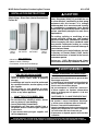 1
1
-
 2
2
-
 3
3
-
 4
4
-
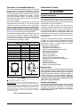 5
5
-
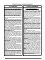 6
6
-
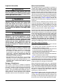 7
7
-
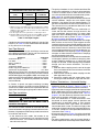 8
8
-
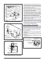 9
9
-
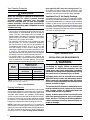 10
10
-
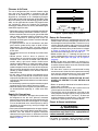 11
11
-
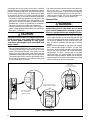 12
12
-
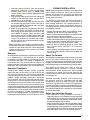 13
13
-
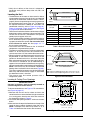 14
14
-
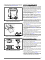 15
15
-
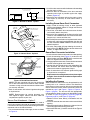 16
16
-
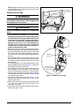 17
17
-
 18
18
-
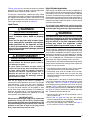 19
19
-
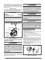 20
20
-
 21
21
-
 22
22
-
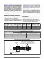 23
23
-
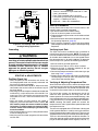 24
24
-
 25
25
-
 26
26
-
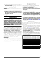 27
27
-
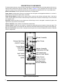 28
28
-
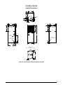 29
29
-
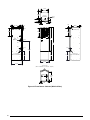 30
30
-
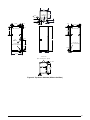 31
31
-
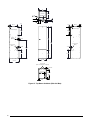 32
32
-
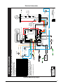 33
33
-
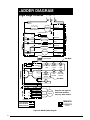 34
34
-
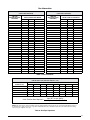 35
35
-
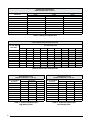 36
36
-
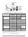 37
37
-
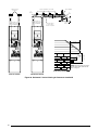 38
38
-
 39
39
-
 40
40


Ask a question and I''ll find the answer in the document
Finding information in a document is now easier with AI
Related papers
-
Broan MG2R Installation guide
-
Unbranded PPG2GF-A Installation guide
-
Broan PPG3HE-A, Single Phase Installation guide
-
-
Broan M5S Installation guide
-
-
-
Broan MG2S Installation guide
-
Broan CMF95 Installation guide
-
Other documents
-
Trane Oxbox 14 Seer J4PG4030A1060AA Installation Instructions Manual
-
 GOODMAN GMPH080-5 Series User manual
-
-
-
Frigidaire FLCG7522AW Spec sheet
-
Frigidaire FLCE7522AW Specification
-
-
Broan M7RL Series Installation guide
-
Intertherm M7RL Series Installation Instructions Manual
-
Broan FG8SA User manual
