
ENGLISH_index
Safety and Reference
OWNER’S MANUAL
Please read this manual carefully
before operating your set and retain it
for future reference.
The model and serial number of the product are
located on the back and on one side of the product.
Record them below in case you ever need service.
Model
Serial No.
www.lg.com
Copyright © 2023 LG Electronics Inc.
All Rights Reserved.
*MFL719463392308REV02*

2
Before reading this manual
•Read this manual thoroughly before operating your product, and keep it for future reference.
•On the website you can download the manual including installation, using, troubleshooting, specifications, license etc and view its contents on your PC or
mobile device.
•User Guide : For more information about this product, read the USER GUIDE embedded in the product. (Depending on model)
-To open the USER GUIDE → [ ] → [Support] → [User Guide]
Separate Purchase
•Separate purchase items can be changed or modified for quality improvement without any notification. Contact your dealer to buy these items. These
devices only work with certain models.
•The model name or design may be changed depending on the upgrade of product functions, manufacturer’s circumstances or policies.
•A cable to connect antennas and external devices must be purchased separately.
Note
•Product specifications or contents of this manual may be changed without prior notice due to upgrade of product functions.
•The items supplied with your product may vary depending on the model.
•Image shown may differ from your product.
Warning! Safety instructions
CAUTION
RISK OF ELECTRIC SHOCK
DO NOT OPEN
CAUTION : TO REDUCE THE RISK OF ELECTRIC SHOCK, DO NOT REMOVE COVER (OR BACK). NO USER-SERVICEABLE PARTS INSIDE. REFER TO QUALIFIED SERVICE
PERSONNEL.
This symbol is intended to alert the user to the presence of uninsulated “dangerous voltage” within the product’s enclosure that may be of sufficient
magnitude to constitute a risk of electric shock to persons.
This symbol is intended to alert the user to the presence of important operating and maintenance (servicing) instructions in the literature
accompanying this apparatus.
WARNING : TO REDUCE THE RISK OF FIRE AND ELECTRIC SHOCK, DO NOT EXPOSE THIS PRODUCT TO RAIN OR MOISTURE.
•TO PREVENT THE SPREAD OF FIRE, KEEP CANDLES OR OTHER ITEMS WITH
OPEN FLAMES AWAY FROM THIS PRODUCT AT ALL TIMES.
•Do not place the product and/or remote control in the following
environments:
-Keep the product away from direct sunlight.
-An area with high humidity such as a bathroom.
-Near any heat source such as stoves and other devices that produce
heat.
-Near kitchen counters or humidifiers where they can easily be exposed
to steam or oil.
-An area exposed to rain or wind.
-Do not expose to dripping or splashing and do not place objects filled
with liquids, such as vases, cups, etc. on or over the apparatus (e.g., on
shelves above the unit).
-Near flammable objects such as gasoline or candles, or expose the
product to direct air conditioning.
-Do not install in excessively dusty places.
-On unsecured or high furniture, such as shelves or bookshelves.
Otherwise, this may result in fire, electric shock, combustion/explosion,
malfunction or product deformation.
•Ventilation
-Install your product where there is proper ventilation. Do not install in
a confined space such as a bookcase.
-Do not install the product on a carpet or cushion.
-Do not block or cover the product with cloth or other materials while
unit is plugged in.
•Take care not to touch the ventilation openings. When watching the
product for a long period, the ventilation openings may become hot.

3
•Keep a distance of at least 10 cm away from other objects so that the
vents of the Zero Connect Box are not blocked.
-An increase in the internal temperature of the product may result in
fire and product failure.
•Protect the power cord from physical or mechanical abuse, such as being
twisted, kinked, pinched, closed in a door, or walked upon. Pay particular
attention to plugs, wall outlets, and the point where the cord exits the
device.
•Do not move the product whilst the Power cord is plugged in.
•Do not use a damaged or loosely fitting power cord.
•Be sure to grasp the plug when unplugging the power cord. Do not pull
on the power cord to unplug the product.
•Do not connect too many devices to the same AC power outlet as this
could result in fire or electric shock.
•Disconnecting the Device from the Main Power
-The power plug is the disconnecting device. In case of an emergency,
the power plug must remain readily accessible.
•Do not let your children climb or cling onto the product. Otherwise, the
product may fall over, which may cause serious injury.
•Outdoor Antenna Grounding (Can differ by country):
-If an outdoor antenna is installed, follow the precautions below.
An outdoor antenna system should not be located in the vicinity of
overhead power lines or other electric light or power circuits, or where
it can come in contact with such power lines or circuits as death or
serious injury can occur.
•Never touch this apparatus or antenna during a lightning storm. You may
be electrocuted.
•Make sure the power cord is connected securely to the product and wall
socket if not secured damage to the Plug and socket may occur and in
extreme cases a fire may break out.
•Do not insert metallic or inflammable objects into the product. If a
foreign object is dropped into the product, unplug the power cord and
contact the customer service.
•Do not touch the end of the power cord while it is plugged in. You may
be electrocuted.
•If any of the following occur, unplug the product immediately
and contact your local customer service.
-The product has been damaged.
-If water or another substance enters the product (like an AC adapter,
power cord, or product).
-If you smell smoke or other odors coming from the product.
-When lightning storms or when unused for long periods of time.
Even the product is turned off by remote control or button, AC power
source is connected to the unit if not unplugged in.
•Do not use high voltage electrical equipment near the product (e.g., a
bug zapper). This may result in product malfunction.
•Do not attempt to modify this product in any way without written
authorization from LG Electronics. Accidental fire or electric shock
can occur. Contact your local customer service for service or repair.
Unauthorized modification could void the user’s authority to operate
this product.
•Use only an authorized attachments / accessories approved by LG
Electronics. Otherwise, this may result in fire, electric shock, malfunction,
or product damage.
•Never disassemble the AC adapter or power cord. This may result in fire
or electric shock.
•Handle the adapter carefully to avoid dropping or striking it. Do not
subject the adaptor to external shock. An impact could damage the
adapter.
•To reduce the risk of fire or electrical shock, do not touch the product
with wet hands. If the power cord prongs are wet or covered with dust,
dry the power plug completely or wipe dust off.
•Batteries
-Store the accessories (battery, etc.) in a safe location out of the reach
of children.
-Do not short circuit, disassemble, or allow the batteries to overheat.
Do not dispose of batteries in a fire. Batteries should not be exposed
to excessive heat.
-Caution: Use the correct batteries for the product. Risk of fire or
explosion if the battery is replaced by an incorrect type.
•Moving
-When moving, make sure the product is turned off, unplugged, and
all cables have been removed. It may take 2 or more people to carry
larger products. Do not press or put stress on the front panel of the
product. Otherwise, this may result in product damage, fire hazard
or injury.
•Keep the packing anti-moisture material or vinyl packing out of the
reach of children.
•Do not allow an impact shock, any objects to fall into the product, and do
not drop anything onto the screen.
•Do not press strongly upon the panel with a hand or a sharp object such
as a nail, pencil, or pen, or make a scratch on it. It may causedamage
to screen.
•Do not hold the product screen, scratch the surface with a metal object,
or apply impact to it.
-The screen may break, resulting in personal injury or malfunction of
the product.
•Do not push or kick the product.
•Do not place heavy objects on top of the product.
•Be careful if you have pets
•Cleaning
-When cleaning, unplug the power cord and wipe gently with a soft/
dry cloth. Do not spray water or other liquids directly on the product.
Do not clean your product with chemicals including glass cleaner,
any type of air freshener, insecticide, lubricants, wax (car, industrial),
abrasive, thinner, benzene, alcohol etc., which can damage the
product and/or its panel. Otherwise, this may result in electric shock
or product damage.

4
Installation
Lifting and moving the TV Screen
Please note the following advice to prevent the TV screen from being
scratched or damaged and for safe transportation regardless of its type and
size.
•It is recommended to move the TV screen in the box or packing material
that the TV screen originally came in.
•Before moving or lifting the TV screen, disconnect the power cord and
all cables.
•When holding the TV screen, the screen should face away from you to
avoid damage.
•Hold the side and bottom of the TV screen frame firmly. Make sure not to
hold the transparent part, speaker, or speaker grill area.
•When transporting a large TV screen, there should be at least 2 people.
•When transporting the TV screen, do not expose the TV screen to jolts or
excessive vibration.
•When transporting the TV screen, keep the TV screen upright, never turn
the TV screen on its side or tilt towards the left or right.
•Do not apply excessive pressure to cause flexing / bending of frame
chassis as it may damage screen.
•When handling the TV screen, be careful not to damage the protruding
buttons.
•Avoid touching the screen at all times, as this may result in damage to
the screen.
•When attaching the stand to the TV set, place the screen facing down on
a cushioned table or flat surface to protect the screen from scratches.
Mounting on the Table
(Depending on model)
1 Lift and tilt the TV screen into its upright position on a table.
• Leave a 10cm (minimum) space from the wall for proper ventilation.
(Depending on model)
2 Connect the power cord to a wall outlet.
•Do not apply foreign substances (oils, lubricants, etc.) to the screw parts
when assembling the product. (Doing so may damage the product.)
•Do not use any unapproved items to ensure the safety and product life
span.
•Any damage or injuries caused by using unapproved items are not
covered by the warranty.
•If you install the TV on a stand, you need to take actions to prevent the
product from overturning. Otherwise, the product may fall over, which
may cause injury.
•When assembling the stand, ensure that all of the provided screws are
attached. If the screws are not fully tightened, the product may tilt or
tip over, resulting in damage. Tightening the screws with excessive force
may cause them to come off due to abrasion of the screw joint.
•If the TV screen is placed on the stand, its screen may be tilted back
slightly. If the stand is not level because an object is placed under the
stand or it is not on a flat surface, the product may fall and cause injury
or product damage. (Depending on model)
Securing TV screen to the Wall
(Depending on model)
1 Insert and tighten the eye-bolts, or TV brackets and bolts on the back of
the TV.
• If there are bolts inserted at the eye-bolts position, remove the bolts
first.
2 Mount the wall brackets with the bolts to the wall. Match the location of
the wall bracket and the eye-bolts on the rear of the TV.
3 Connect the eye-bolts and wall brackets tightly with a sturdy rope. Make
sure to keep the rope horizontal with the flat surface.
•Use a platform or cabinet that is strong and large enough to support the
TV securely.
•Brackets, bolts and ropes are not provided. You can obtain additional
accessories from your local dealer.

5
Mounting to the Wall
(Depending on model)
Attach an optional wall mount bracket at the rear of the TV carefully and
install the wall mount bracket on a solid wall perpendicular to the floor.
When you attach the TV to other building materials, please contact qualified
personnel. LG recommends that wall mounting be performed by a qualified
professional installer. We recommend the use of LG’s wall mount bracket.
LG’s wall mount bracket is easy to move with cables connected. When you
do not use LG’s wall mount bracket, please use a wall mount bracket where
the device is adequately secured to the wall with enough space to allow
connectivity to external devices. It is advised to connect all the cables before
installing fixed wall mounts.
•Remove the stand before installing the TV on a wall mount by
performing the stand attachment in reverse.
•For more information of screws and wall mount bracket, refer to the
Separate Purchase.
•If you intend to mount the product to a wall, attach VESA standard
mounting interface (optional parts) to the back of the product. When
you install the set to use the wall mounting bracket (optional parts), fix
it carefully so as not to drop.
•When mounting a TV on the wall, make sure not to install the TV by
hanging the power and signal cables on the back of the TV.
•Do not install this product on a wall if it could be exposed to oil or oil
mist. This may damage the product and cause it to fall.
•When installing the Full Contact Wall Mount, the TV may not be
contacted firmly against the wall due to some wall conditions.
Antenna/Cable
Connect the TV to a wall antenna socket with an RF cable (75Ω).
•Use a signal splitter to use more than 2 TVs.
•If the image quality is poor, install a signal amplifier properly to improve
the image quality.
•If the image quality is poor with an antenna connected, try to realign the
antenna in the correct direction.
•An antenna cable and converter are not supplied.
•For a location that is not supported with Ultra HD broadcasting, this TV
cannot receive Ultra HD broadcasts directly.
Satellite dish
Connect the TV to a satellite dish to a satellite socket with a satellite RF cable
(75Ω). (Depending on model)

6
Starting TV
Turning on the TV
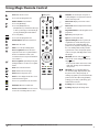
You can simply operate the TV functions, using the button.
Power On (Press)
Power Off1) (Press and Hold)
Menu Control (Press2))
Menu Selection (Press and Hold3))
1) All running apps will close, and any recording in progress will stop.
(Depending on country)
2) You can access and adjust the menu by pressing the button when TV is on.
3) You can use the function when you access menu control.
Note
•If the TV is turned on for the first time after it was shipped from the
factory, initialization of the TV may take a few minutes.
•Your TV’s OSD (On Screen Display) may differ slightly from that shown
in this manual.
•The device must be easily accessed to a location outlet near the access.
Some devices are not made by turning on / off button, turning off the
device and unplugging the power cord.
•Only use the power button when the TV screen and the Zero Connect Box
are connected.
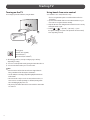
Using hands-free voice control
To use hands-free voice control, follow these steps.
•The voice recognition microphone is on the front bottom of the Zero
Connect Box.
1 If you direct the front LED of the Zero Connect Box towards the user, you
can use the voice recognition function smoothly.
2 Adjust the direction of the sliding button toward the TV Screen receiver by
turning the dial left or right.
3 From the → [ ] → [General] → [AI Service] → [Voice
Recognition Settings] screen, turn on the [Use Hands-free Voice Control]
menu. (Depending on model)

7
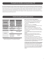
Precautions before using wireless TV
Wireless TVs use high-frequency radio waves of 60 GHz to transmit a large amount of data in a very short time, enabling wireless transmission of high-quality
video and audio. The 60 GHz frequency band used in wireless TVs is advantageous for large-capacity data transmission, has good linearity, and is well-suited for
transmission and reception in a specific direction. However, if there is a metallic object in the transmission/reception path, the radio waves cannot pass through
it. Non-conductive objects (e.g., glass, wood, plastic) may attenuate the signal, resulting in communication failure. Due to such characteristics of radio waves,
viewing is not affected when the wireless TV transmitting and receiving antennas are facing each other; however, if there are obstacles in the transmission/
reception path, the wireless signal may be attenuated or disconnected, resulting in inconvenience during viewing. This is not a product malfunction. Follow the
installation method provided when using the product.
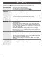
Understanding 60 GHz wireless
Characteristics of
radio waves
Frequencies in
the 60 GHz band
applied to wireless
TVs
(high frequency)
Frequencies applied
to general wireless
communication (cell
phone, WiFi/BT)
(low frequency)
Linearity Strong Weak
Transmission volume High Low
Directionality Ideal for transmission
in specific direction
Ideal for broad
coverage
Attenuation
High loss
(linearity)
Low loss and good
avoidance (diffraction)
Radio waves
absorbed by water
droplets and water
vapour in the air
Good obstacle
avoidance
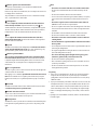
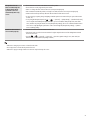
•This product satisfies the standards for protecting the human body
against electromagnetic waves*. (*Meets IEC62311 standards)
•Wireless TVs use frequencies in the 60 GHz band.
•The 60 GHz band is also known as millimetre wave (mmWave), and
enables the transmission of large data volumes without delays.
•The 60 GHz band is a high-frequency band used in satellite
communication.
•High-frequency bands have excellent linearity.
•High linearity is ideal for transmission in a specific direction; however,
obstacles cause greater attenuation loss.
•Path loss occurs due to the presence of multiple paths created by
diffraction, refraction, reflection, etc. The multiple path loss resulting
from diffraction, refraction, and reflection causes antenna transmission
and reception failure.
•Generally, wireless radio waves experience interference from
obstacles.
•Conductive obstacles (metal) shield the frequency (antenna
transmission/reception), whereas non-conductive obstacles (glass,
wood, and plastic) cause attenuation.
•Radio waves using high frequencies in the 60 GHz band (short
wavelengths) provide optimal image through the use of beamforming
technology. Beamforming technology arranges multiple antennas at
regular intervals, adjusts the amplitude and phase of the signal supplied
to each antenna, and creates an antenna beam in a specific direction to
strongly transmit and receive signals to that direction.
•For optimal image viewing, the transmission/reception must be facing
each other, that is, have an unobstructed Line Of Sight (LOS).
•LOS is the visible path, which must be clear of obstacles in the way. If
there are obstacles, the receiver must be high enough that it is visible.
That is, the receiver must be higher than the transmitter. (For wireless
TVs, the Zero Connect Box must be placed lower than the TV
Screen.)

8
Details for wireless TV (TV Screen + Zero Connect Box)
Viewing appearance
TV Screen
Zero Connect Box (WM23EA)
Front Back
Side

9
Wireless signal receiver & Power button
This area has an antenna that receives the video transmitted from the
antenna of the Zero Connect Box.
If there are any obstacles around this area, the screen may be disconnected or
not displayed due to interference.
The power button is used to turn the TV Screen on or switch to the standby
state, or pair it with the Zero Connect Box.
Sliding button
This button adjusts the antenna transmission direction of the Zero
Connect Box up and down. If adjusted towards the top LED ( ), the
antenna transmission direction is downward (0˚). If adjusted in the opposite
direction of the top LED, the antenna transmission direction is upward (50˚).
If adjusted to the centre, the antenna transmission direction is at 25˚.
Dial
This disc adjusts the antenna transmission direction of the Zero
Connect Box left and right. The dial can be rotated 90˚ left or right from
the front of the Zero Connect Box.
Top LED
This LED is located in front of the sliding button and indicates the wireless
signal strength with different colours. The colours include blue (good),
green (moderate), yellow (weak), and red (disconnected).
Wireless signal transmitter
This area has an antenna that transmits video and audio from the
Zero Connect Box to the TV Screen. The antenna transmission direction
is adjusted using the dial and sliding button. If there is an obstacle in front
of the antenna, the screen may disconnect or display incorrectly due to
interference.
Voice recognition unit
This area recognises your voice and is located on the lower left and right sides
of the front of the Zero Connect Box.
When giving a voice command, speak from the front of the Zero Connect
Box. If the area with the voice recognition parts is blocked or if you speak
from the side or back, voice recognition may function poorly or not work at
all.
Front LED
This LED is located at the bottom centre of the front of the Zero Connect Box
and indicates the power or operation status.
External connection terminal
You can connect the Zero Connect Box's power cord and external video/audio
devices such as external antennas and set-top boxes.
Pairing button
This button is used to re-pair the TV Screen and Zero Connect Box if they have
been unpaired. For pairing instructions, please refer to "Re-pairing" on the
right.
Note
•The wireless TV consists of the TV Screen and Zero Connect Box.
•The Zero Connect Box transmits video and audio wirelessly to the TV
Screen.
•The Zero Connect Box has external connection terminals.
•You can connect video and audio signals (external antenna, set-top box)
to the external connection terminals on the back of the Zero Connect
Box.
•The wireless signal receiver is on the bottom centre of the TV
Screen. It is next to the TV Screen power button.
•The voice recognition unit is on the lower left and right sides of the front
of the Zero Connect Box. Ensure there is no dust or foreign matter in the
small hole.
•The front LED is on the bottom of the front of the Zero Connect Box.
•The Zero Connect Box has wireless connection control terminals.
•The wireless connection control terminals consist of a dial and
a sliding button.
•The dial and wireless signal transmitter of the Zero Connect Box
move together.
•You can adjust the Zero Connect Box’s wireless signal transmitter up and
down using the sliding button.
•The signal strength LED for checking the wireless connection status is in
front of the sliding button on the top.
•The colours indicating signal strength are blue (good), green
(moderate), yellow (weak), and red (disconnected).
•The Zero Connect Box has a pairing button.
•There is a button for pairing on the TV Screen as well, which can also be
used as the power button.
•The TV Screen and the Zero Connect Box are paired one to one and are
already paired when provided.
Re-pairing
1 If the screen is not displayed due to the TV Screen and Zero Connect Box
being disconnected, they need to re-paired. If you press and hold the
pairing button on the back of the Zero Connect Box for 5 seconds, the top
LED flashes white.
2 If you press and hold the power button on the TV Screen for 5 seconds, the
standby indicator of the screen’s power unit flashes white. The TV Screen
and Zero Connect Box are now paired, and the LED on the top of the Zero
Connect Box changes to the colour corresponding to the signal strength.
* If video is not displayed and the pairing screen remains, contact customer
service.
* If pairing is not resumed within one minute, it will be cancelled and must
be initiated again.

10
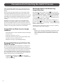
Wireless default placing and setting
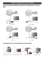
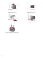
Recommended installation methods (installing Zero Connect
Box)
Frontal installation Diagonal installation
Side installation Bottom installation
Installation don’ts (installing Zero Connect Box)
Installing on shelf above TV Screen Installing on wall behind TV Screen Installing behind wall Installing inside the cabinet

11
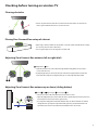
Checking before turning on wireless TV
Clearing obstacles
•Remove any obstacles between the TV Screen and Zero Connect Box. If there are obstacles, the
wireless signal is attenuated and causes screen disconnection.
Placing Zero Connect Box on top of cabinet
•When using a cabinet, install the Zero Connect Box on top of the cabinet. If installed inside a cabinet,
the screen may disconnect due to interference.
•Voice recognition may also become degraded or not work at all.
Adjusting Zero Connect Box antenna left or right (dial)
Sliding button Dial
•Adjust the dial on the Zero Connect Box left or right until the sliding button faces the wireless
receiver on the TV Screen.
•By adjusting the dial, you can move the direction of the wireless signal transmission of the Zero
Connect Box left or right. You can adjust the dial up to 90˚ left or right from the front LED.
Adjusting Zero Connect Box antenna up or down (sliding button)
Down Up Highest angle Lowest angle 50˚
•Place the Zero Connect Box lower than the TV Screen wireless receiver.
•Adjust the sliding button up or down so that the wireless signal transmission direction of the Zero
Connect Box faces the TV Screen wireless signal receiver.
•If you adjust the sliding button towards the LED (blue line), the antenna transmits in a forward
straight direction. If you adjust it away from the LED (green line), the antenna transmits in an
upward direction. The Zero Connect Box antenna transmits in the 0-50˚ direction.

12
Checking after turning on wireless TV
Checking wireless signal strength on Zero Connect
Box (top LED colour)
•Once default placing and settings are completed, check the colour of the top LED in front of the
sliding button of the Zero Connect Box.
•The colour of the top LED indicates the wireless signal strength.
•The colours are blue (good), green (moderate), yellow (weak), and red (disconnected). Blue
(good) indicates the best viewing screen condition. Blue is recommended. Adjust the settings
so that the colour displays blue.
Setting wireless signal strength to blue (good) on
Zero Connect Box
•If the colour is red, ensure there are no obstacles or check its position on the cabinet.
•If the colour is yellow or green, adjust the Zero Connect Box antenna left and right (dial) or up
and down (sliding button).
Identifying wireless reception range
TV Screen
The distance between the TV Screen antenna receiver and the Zero Connect Box antenna transmitter should be within 10 m of the front for stable
operation.
The distance between the TV Screen antenna receiver and the Zero Connect Box antenna transmitter should be within 5 m diagonally for stable
operation.
The distance between the TV Screen antenna receiver and the Zero Connect Box antenna transmitter should be within 3 m of the side for stable
operation.
The distance between the TV Screen antenna receiver and the Zero Connect Box antenna transmitter should be within 3 m of the bottom for stable
operation.
* The distances above are based on the condition that there are no obstacles. When installing a sound bar in front of the TV Screen, ensure that it does not
cover the wireless receiver on the TV Screen. It is recommended to install the sound bar at a sufficient distance from the wireless receiver on the TV Screen.

13
Precaution Notes
Wireless Precaution Notes
•The quality of the image and audio may deteriorate depending on the installation environment (installed location, surrounding devices,
obstacles, and distance).
•Do not place obstacles between the TV Screen and Zero Connect Box. The screen may fail to display due to interference from obstacles.
•Ensure that there are no obstacles between the Zero Connect Box and TV Screen.
•If the Zero Connect Box is installed inside the cabinet, the screen may fail to display, depending on the cabinet material (marble, wood, etc.) and
thickness, and the voice recognition function may also deteriorate.
•Do not install two wireless TVs or Zero Connect Boxes in the same room. The screen may fail to display due to interference.
•When used with an external device using a 60 GHz frequency, the screen may fail to display due to mutual interference.
•If you place electronic devices and objects on top of the Zero Connect Box, the screen may fail to display properly due to interference.
•If a person or animal passes between the Zero Connect Box and the TV Screen while you are watching TV, the screen may disconnect.
•Failure to follow the recommended installation method may result in abnormal operation.
Voice Recognition Precaution Notes
•Speaking from directions other than the front of the Zero Connect Box where the voice recognition unit is located may cause the voice recognition
function to deteriorate.
•Do not place any obstacles in front of the Zero Connect Box where the voice recognition unit is located.
•Please keep the small hole of the voice recognition unit free from dust or any foreign matter.
•Failure to follow the recommended installation method may result in poor or non-functional voice recognition.
Installation Precaution Notes
•Do not install the Zero Connect Box on a shelf above the TV Screen. The antenna path does not align with the Zero Connect Box antenna transmitter and
the screen does not display properly due to shelf interference.
•Do not install the Zero Connect Box on the wall behind the TV Screen. The screen does not display because the wireless signal is shielded.
•Do not install the Zero Connect Box behind a wall. The screen does not display because the wireless signal is shielded by the wall.
•Do not install the Zero Connect Box inside a metal cabinet. The screen does not display because the signal is shielded. Thick materials such as marble,
glass, or wood may also cause wireless failure and prevent the screen from displaying properly.
•Failure to follow the recommended installation method may result in the screen not displaying.
•Ensure that the wireless receiver on the TV Screen does not come into contact with the wireless transmitter on the Zero Connect Box.
•After cleaning or moving the Zero Connect Box, check and adjust the colour of the LED on the top. The screen may not display because of the change in
installation environment.

14
Installing on shelf above TV Screen Installing on wall behind TV Screen
Installing behind wall Installing inside the cabinet
Placing electronic devices on top of Zero Connect Box

15
Installing according to usage scenarios
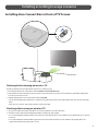
Installing Zero Connect Box in front of TV Screen
Checking before turning on wireless TV
If you have installed the Zero Connect Box in front of the TV Screen, follow these steps.
1 Direct the front LED of the Zero Connect Box towards the wireless receiver on the TV Screen.
2 If the front LED is not directed towards the TV Screen wireless receiver, turn the dial on top of the Zero Connect Box left or right until the sliding button
faces the TV Screen wireless receiver.
3 Adjust the sliding button on the Zero Connect Box towards the top LED.
•Once the dial and sliding button adjustments are completed, the signal transmission and reception path should be in the green direction shown in the
figure.
•Ensure there are no obstacles in the antenna transmission and reception path.
Checking after turning on wireless TV
1 Once you have completed all settings, check that the colour of the top LED of the Zero Connect Box is blue.
2 If the LED is not blue, adjust the dial and sliding button further to optimise the signal condition.
•It is recommended that the installation distance between the Zero Connect Box and the TV Screen be within 10 m. (provided that there are no obstacles
in the way)
•It is recommended that the frontal installation angle between the Zero Connect Box and the TV Screen be within 45˚ left and right. (Refer to the
diagonal/side installation image if the angle is over 45˚.)

16
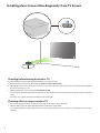
Installing Zero Connect Box diagonally from TV Screen
Checking before turning on wireless TV
If you have installed the Zero Connect Box diagonally from the TV Screen, follow these steps.
1 Direct the front LED of the Zero Connect Box towards the wireless receiver on the TV Screen.
2 If the front LED is not directed towards the TV Screen wireless receiver, turn the dial on top of the Zero Connect Box left or right until the sliding button
faces the TV Screen wireless receiver.
3 Adjust the sliding button on the Zero Connect Box towards the top LED.
•Once the dial and sliding button adjustments are completed, the signal transmission and reception path should be in the green direction shown in the
figure.
•Ensure there are no obstacles in the antenna transmission and reception path.
Checking after turning on wireless TV
1 Once you have completed all settings, check that the colour of the top LED of the Zero Connect Box is blue.
2 If the LED is not blue, adjust the dial and sliding button further to optimise the signal condition.
•It is recommended that the installation distance between the Zero Connect Box and the TV Screen be within 5 m. (provided that there are no obstacles
in the way)

17
Installing Zero Connect Box to the side of TV Screen
Checking before turning on wireless TV
If you have installed the Zero Connect Box to the side of the TV Screen, follow these steps.
1 Direct the front LED of the Zero Connect Box towards the wireless receiver on the TV Screen.
2 If the front LED is not directed towards the TV Screen wireless receiver, turn the dial on top of the Zero Connect Box left or right until the sliding button
faces the TV Screen wireless receiver. (If the front LED of the Zero Connect Box faces the viewing direction, turn the dial left or right until it is at a 90°
angle.)
3 Adjust the sliding button on the Zero Connect Box to the centre.
•Once the dial and sliding button adjustments are completed, the signal transmission and reception path should be in the green direction shown in the
figure.
•Ensure there are no obstacles in the antenna transmission and reception path.
Checking after turning on wireless TV
1 Once you have completed all settings, check that the colour of the top LED of the Zero Connect Box is blue.
2 If the LED is not blue, adjust the dial and sliding button further to optimise the signal condition.
•It is recommended that the installation distance between the Zero Connect Box and the TV Screen be within 3 m. (provided that there are no obstacles
in the way)

18
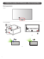
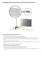
Installing Zero Connect Box to the bottom of TV Screen
Checking before turning on wireless TV
If you have installed the Zero Connect Box to the bottom of the TV Screen, follow these steps.
1 Position the Zero Connect Box so that the front LED is facing the viewer in front of the TV Screen.
2 Turn the dial on the top of the Zero Connect Box left or right to adjust the direction of the sliding button towards the viewer.
3 Adjust the sliding button on the Zero Connect Box in the opposite direction of the top LED.
•Once the dial and sliding button adjustments are completed, the signal transmission and reception path should be in the green direction shown in the
figure.
•Ensure there are no obstacles in the antenna transmission and reception path.
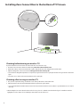
Checking after turning on wireless TV
1 Once you have completed all settings, check that the colour of the top LED of the Zero Connect Box is blue.
2 If the LED is not blue, adjust the dial and sliding button further to optimise the signal condition.
•It is recommended that the installation distance between the Zero Connect Box and the TV Screen be within 3 m. (provided that there are no obstacles
in the way)
* When installing the Zero Connect Box at the bottom of the TV screen, please do so within the area indicated in the figure. For installation outside the
highlighted area on the cabinet, refer to "Installing Zero Connect Box to the side of TV Screen."

19
Connections
Connect various external devices to the TV and switch input modes to select
an external device. For more information of external device’s connection, refer
to the manual provided with each device.
HDMI
•When connecting the HDMI cable, the product and external devices
should be turned off and unplugged.
•Supported HDMI Audio format (Depending on model):
True HD (48kHz),
Dolby Digital / Dolby Digital Plus (32kHz, 44.1kHz, 48kHz),
PCM (32kHz, 44.1kHz, 48kHz, 96kHz, 192kHz),
DTS (44.1kHz, 48kHz, 88.2kHz, 96kHz),
DTS-HD (44.1kHz, 48kHz, 88.2kHz, 96kHz, 176.4kHz, 192kHz)
Note
•If the device connected to Input Port also supports HDMI Deep Colour,
your picture may be clearer. However, if the device doesn’t support it, it
may not work properly. In that case, change the TV’s [HDMI Deep Colour]
setting to off.
• → [ ] → [General] → [External Devices] → [HDMI Settings]
→ [HDMI Deep Colour]
•Use a certified cable with the HDMI logo attached.
•If you do not use a certified HDMI cable, the screen may not display or a
connection error may occur.
•Recommended HDMI Cable Types
-Ultra High Speed HDMI®/™ cable (3m or less)
USB
You can connect a USB hub that enables you to use multiple USBs
simultaneously to the Zero Connect Box.
Some USB Hubs may not work. If a USB device connected using a USB Hub is
not detected, connect it to the USB port on the zero connect box directly.
Note
•For an optimal connection, HDMI cables and USB devices should have
bezels less than 10mm thick and 18mm width.
•Use an extension cable that supports if the USB cable or USB
memory stick does not fit into your zero connect box’s USB port.
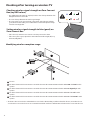
IR Blaster
Control the set-top box (cable/satellite/IP/OTT), Blu-ray/DVD player,
soundbar, game consoles, etc., using the IR Blaster. (Depending on country)
Note
•Connect the IR Blaster cable to the TV’s IR Blaster port.
•Use universal control settings to control the device.
•Secure the IR Blaster with the 3M tape provided.
•When installing the Zero Connect Box in a location other than the
bottom of the TV, we recommend connecting an IR blaster to ensure
smooth control of external devices (e.g., set-top box) using your TV
remote control.
External Devices
Available external devices are: Blu-ray player, HD receivers, DVD players, VCRs,
audio systems, USB storage devices, PC, gaming devices, and other external
devices.
Note
•The external device connection may differ from the model.
•In PC mode, there may be noise associated with the resolution, vertical
pattern, contrast or brightness. If noise is present, change the PC output
to another resolution, change the refresh rate to another rate or adjust
the brightness and contrast on the [Picture] menu until the picture is
clear.
•In PC mode, some resolution settings may not work properly depending
on the graphics card.
•If Ultra HD content is played on your PC, video or audio may become
disrupted intermittently depending on your PC’s performance.
(Depending on model)
•When connecting to a wired LAN, use a CAT7 cable with high-speed
Internet transmission. (Only when port is provided.)
•TV audio can be transmitted to the sound bar (external audio device).
(Depending on country)
-If you want to transmit audio in a wired way (optical digital, HDMI
ARC), you can connect it to the external terminal on the rear of the
Zero Connect Box.
-You can wirelessly transmit audio through the WOWCAST function to
our sound bars that support WOWCAST.

20
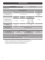
Specications
Power requirement AC 100-240 V~ 50/60 Hz
(Depending on country)
Broadcasting Specifications
Digital TV Analogue TV
Television system DVB-T/T2, DVB-C, DVB-S/S2
PAL B/B, PAL B/G, PAL
D/K, PAL-I,
SECAM B/G, SECAM D/K,
NTSC-M
Programme coverage
DVB-S/S2 DVB-C DVB-T/T2
46 ~ 862 MHz
950 ~ 2,150 MHz 46 ~ 890 MHz
VHF III : 174 ~ 230 MHz
UHF IV : 470 ~ 606 MHz
UHF V : 606 ~ 862 MHz
S Band II : 230 ~ 300 MHz
S Band III : 300 ~ 470 MHz
Maximum number of storable
programmes 6,000 3,000
External antenna impedance 75Ω
CI Module (W x H x D) 100.0mm x 55.0mm x 5.0mm
Environment Condition
Operating Temperature 0°C to 40°C Storage Temperature -20°C to 60°C
Operating Humidity Less than 80% Storage Humidity Less than 85%
Conditions for Wall Mount Installation
Tilt Angle 0° - 15°
* This specification applies only to products with an adjustable wall mount angle.
•For information of the power supply and power consumption, refer to the label attached to the product.
-The typical power consumption is measured in accordance with IEC 62087 or each country’s energy regulations.
-See the label on the bottom of the product for power source, power ratings and product information.
* On some models, the label is inside the external device connection terminal cover.
* Depending on the model or country, the typical power consumption may not be on label.
Page is loading ...
Page is loading ...
Page is loading ...
Page is loading ...
Page is loading ...
Page is loading ...
-
 1
1
-
 2
2
-
 3
3
-
 4
4
-
 5
5
-
 6
6
-
 7
7
-
 8
8
-
 9
9
-
 10
10
-
 11
11
-
 12
12
-
 13
13
-
 14
14
-
 15
15
-
 16
16
-
 17
17
-
 18
18
-
 19
19
-
 20
20
-
 21
21
-
 22
22
-
 23
23
-
 24
24
-
 25
25
-
 26
26


Ask a question and I''ll find the answer in the document
Finding information in a document is now easier with AI
Related papers
Other documents
-
Nissan Quest Owner's manual
-
Nissan Armada 2012 Owner's manual
-
-
Infiniti 2014 Owner's manual
-
-
Zebra VH10 Owner's manual
-
Nissan 2014 370Z Owner's manual
-
-
-