Liebherr SIF5181 Installation guide

Type
Installation guide
Installation Guide
Quality, Design and Innovation
home.liebherr.com/fridge-manuals
Contents
1 General safety instructions.......................... 2
2 Setup conditions........................................... 3
2.1 Space.................................................................... 3
2.2 Setting up multiple appliances......................... 3
2.3 Electrical connection.......................................... 4
3 Appliance dimensions................................... 4
4 Recess dimensions........................................ 5
4.1 Internal dimensions............................................ 5
5 Ventilation requirements.............................. 6
6 Custom panel weights.................................. 6
6.1 Weight................................................................... 6
7 Transporting the appliance........................... 6
8 Unpacking the appliance.............................. 6
9 Setting up the appliance............................... 6
9.1 After setup........................................................... 7
10 Disposal of packaging................................... 7
11 Explanatory symbols used............................ 7
12 **** freezer compartment door.................... 8
12.1 Moving the door hinge........................................ 8
13 Reversing the door........................................ 8
14 Water connection*........................................ 11
15 Connecting the water supply*...................... 11
16 Fit the appliance into the recess.................. 12
17 Cabinet fronts............................................... 20
17.1 Dimensions........................................................... 20
17.2 Mounting the cabinet front(s)........................... 21
17.3 Setting the clearance to avoid collision.......... 21
18 Water tank..................................................... 22
18.1 Inserting the water tank.................................... 22
19 Water filter.................................................... 22
19.1 Installing the water filter................................... 22
20 Connecting the appliance............................. 22
The manufacturer is constantly working to improve all
types and models. Therefore, please be aware that we
reserve the right to make changes to the shape, equip‐
ment and technology.
Symbol Explanation
Read instructions
Please read the information in these
instructions carefully to understand all of
the benefits of your new appliance.
Check appliance
Check all parts for transport damage. If you
have any complaints, please contact your
agent or customer service.
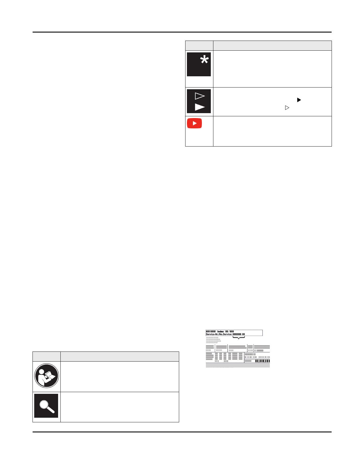
Symbol Explanation
Differences
These instructions apply to a range of
models, so there may be differences.
Sections that apply to certain models only
are indicated by an asterisk (*).
Instructions and results
Instructions are marked with a .
Results are marked with a .
Videos
Videos about the appliances are available
on the YouTube channel of Liebherr-Hausg‐
eräte.
1 General safety instructions
-Please keep this assembly manual in a safe
place so you can refer back to it at any time.
-If you pass the appliance on, please hand
this assembly manual to the new owner.
-Read this assembly manual before installa‐
tion and use in order to use the appliance
safely and correctly. Follow the instructions,
safety instructions and warning messages
included at all times. They are important for
ensuring you can operate and install the
appliance safely and without any problems.
-First read the general safety instructions in
the “General safety instructions” section of
the operating instructions, which accom‐
pany these installation instructions, and
follow them. If you cannot find the oper‐
ating instructions, you can download the
operating instructions from the internet by
entering the service number at
home.liebherr.com/fridge-manuals. The
service number can be found on the serial
tag:
-Observe the warning messages and other
detailed information in the other sections
when installing the appliance:
General safety instructions
2 * Depending on model and options
DANGER indicates a hazardous situa‐
tion, which if not avoided, will
result in death or serious
injury.
WARNING indicates a hazardous situa‐
tion, which if not avoided,
could result in death or serious
injury.
CAUTION indicates a hazardous situa‐
tion, which if not avoided, will
result in minor or moderate
injury.
NOTICE indicates a hazardous situa‐
tion, which if not avoided,
could result in damage to prop‐
erty.
Note indicates useful advice and
tips.
2 Setup conditions
WARNING
Risk of fire due to moisture!
If live parts or the power cord get wet, this can cause a
short circuit.
uThe appliance is designed for use in enclosed
spaces. Do not operate the appliance in open space
or in damp areas or where there is spray.
Normal use
-Only set up and use the appliance in enclosed
spaces.
-Only use once installed.
2.1 Space
WARNING
Leaking refrigerant and oil!
Fire. The refrigerant contained within the appliance is
environmentally friendly, but flammable. The oil
contained within the appliance is flammable. Escaping
refrigerant and oil can ignite if they are of high enough
concentration and are exposed to an external heat
source.
uDo not damage the pipelines of the coolant circuit
and the compressor.
-If the appliance is installed in a very damp environ‐
ment condensate water may form on the outside of
the appliance.
Always make sure the installation area is well venti‐
lated. .
-The more refrigerant there is in the appliance, the
larger the space it is installed in must be. If the
space is too small, any leak may create a flammable
mixture of gas and air. For every 8 g (0.02 lb) of
refrigerant the size of the installation space must be
at least 1 m3 (35.5 ft3). Specifications on the
refrigerant in the appliance can be found on the
serial tag plate inside the appliance.
2.1.1 Installation surface
-The floor of the installation site must be horizontal
and level.
-If the floor is not completely even, level the cabinet
with supports.
2.1.2 Installation position
-Do not install the appliance in direct sunlight or next
to an oven, heater, or similar heat source.
-Only install the appliance in solid cabinets.
2.2 Setting up multiple appliances
NOTICE
Risk of damage caused by water condensate!
uDo not install this device directly beside another
fridge/freezer compartment.
NOTICE
Risk of damage caused by water condensate!
uDo not stack the appliance directly on top of
another.
These appliances are designed for different types of
installation. Only combine appliances if the appliances
are designed for this. The following table shows the
installation options by model:
Setup type Model
Single All models
Side-by-Side
(SBS)
Model that start with S....
Stacked Models with a maximum recess height
of 880 mm (34.64 in) and with a heated
cover can be “stacked”.
Top appliance: to the max. recess
height of 140 mm (5.51 in)
Setup conditions
* Depending on model and options 3
Fig. 1
Install each appliance into its own recess.
2.3 Electrical connection
WARNING
Danger of fire due to incorrect positioning!
If the power supply cable or plug touches the back of
the appliance, the vibration can damage the power
supply cable or the plug resulting in a short circuit.
uMake sure the power supply cable is not trapped
under the appliance when you position the appli‐
ance.
uInstall the appliance so that it does not touch any
plugs or power cables.
uDo not connect any appliances to sockets in the area
of the back of the appliance.
uDo not place and operate power strips/power
distributors and other electronic devices (such as
halogen transformers) at the back of the appliances.
3 Appliance dimensions
Fig. 2
in. mm
A22 559
B21 1/2 546
C69 11/16 1770
D27 3/8 695
E5/8 15
Appliance dimensions
4 * Depending on model and options
Fig. 3
in. mm
A22 559
B21 1/2 546
C69 11/16 1770
4 Recess dimensions
4.1 Internal dimensions
Fig. 4
in. mm
F69 3/4 — 70 3/8 1772 — 1788
G22 — 22 3/4 560 — 578
Hmin. 21 5/8, recom‐
mended 22
min. 550, recom‐
mended 560
Jmin. 19 11/16 min. 500
Lmax. 3/4 max. 19
The specified energy consumption was determined
with a kitchen unit depth of 560 mm (22 in). The
appliance will work properly at a kitchen unit depth of
550 mm (21 5/8 in), but with a slightly higher
energy consumption.
uCheck the wall thickness of adjacent cabinets: It
must be min. 16 mm (5/8 in).
uOnly install the appliance in solid, fixed kitchen cabi‐
nets. Ensure that the cabinets cannot tip over.
uAlign the cabinets with a spirit level and a try
square. If necessary, level them by putting some‐
thing underneath them.
uEnsure that the floor and the side panels of the
cabinet are at right angles to each other.
Recess dimensions
* Depending on model and options 5
5 Ventilation requirements
NOTICE
Covered vents!
Damage. Appliance can overheat, which can reduce the
service life of various parts of the appliance and lead
to functional impairments.
uAlways ensure good ventilation.
uAlways keep vents or ventilation grills in the appli‐
ance housing and in the kitchen structure (built-in
appliance) unobstructed.
uNever block air vents of the fan.
Note
The clearance on the back of the appliance must be
13 mm (1/2 in). If the clearance is less than
13 mm (1/2 in), energy consumption may increase.
Comply with the ventilation gaps:
-The depth of the ventilation shaft on the back wall
of the cabinet must be at least 38 mm (1.5 in).
-At least 200 cm2 (31 in2) is required for the ventila‐
tion cross-sections below the unit at its base and
above the unit in the surrounding cabinet.
-Basically, the larger the ventilation cross-section,
the more efficiently the appliance will run.
Sufficient ventilation is required for the appliance to
operate correctly. The pre-fitted vents ensure an effec‐
tive air-flow cross-section on the appliance of
200 cm2 (31 in2). If you replace the vents with a cover
panel, it must have at least an equal or larger air-flow
cross-section than the manufacturer’s vent.
6 Custom panel weights
6.1 Weight
NOTICE
An excessively heavy custom panel can potentially
cause damage!
If the custom panel is too heavy, damage to the hinges
cannot be ruled out, which may compromise the func‐
tionality of the unit.
uBefore installing the custom panel, ensure the
custom panel does not exceed the permissible
weight.
Recess
heights
(cm)
Appliance type Maximum weight of
the custom panel lb
(kg)
178 IRBhi 51600 /
IRB5160
SIFNhi 51881/
SIF5181
57 (26)
Single-door fridges and freezers
Recess
heights
(cm)
Appliance type Maximum weight of the
custom panel lb (kg)
Fridge
compart
ment door
Freezer
compart‐
ment door
178 ICN 51030/
IC5100PC
ICNh-IM 51130/
IC5110IM
ICN-IM 51130/
IC5110IMPC
ICBNhi-IM
51630/
ICB5160IM
40 (18) 26 (12)
Combinations
7 Transporting the appliance
uOn initial setup: Transport the appliance in its pack
aging.
uWhen transporting after initial setup (e.g. reloca‐
tion): Transport the appliance unloaded.
uTransport the appliance upright.
uUse two people when transporting the appliance.
8 Unpacking the appliance
If the appliance is damaged check with the supplier
immediately before connecting it.
uCheck the appliance and packaging for damage
during transport. If you suspect any damage, please
contact your supplier immediately.
uRemove all materials that could prevent it from
being installed properly or prevent proper ventilation
from the back or the side panels of the appliance.
uRemove all protective films from the appliance. Do
not use sharp or pointed objects for this.
uRemove the mains cable from the back of the appli‐
ance. Also remove the cable holder, otherwise there
will be vibration noise!
9 Setting up the appliance
CAUTION
Risk of personal injury!
uHave two people move this appliance into place.
WARNING
Danger of injury and damage due to the appliance
being unstable!
The appliance can tip over.
uSecure the appliance as described in the instruc‐
tions.
Ventilation requirements
6 * Depending on model and options
WARNING
Danger of fire and damage!
uDo not place devices that give off heat, e.g. micro‐
waves, toasters, etc. on the appliance.
If possible, have a professional install the appliance in
your kitchen cabinet unit.
Do not install the appliance without assistance.
9.1 After setup
uRemove all transport packaging.
Fig. 5 *
uPull off the transport lock
on the appliance door.
*
uClean the appliance (see User Guide, Cleaning the
appliance).
uWrite down the type (model, number), appliance
name, appliance/serial number, date of purchase
and dealer address in the designated fields (see
User Guide, About the appliance).
10 Disposal of packaging
WARNING
Danger of suffocation from packaging materials and
films!
uDo not allow children to play with packaging mate‐
rials.
The packaging is made from recyclable mate‐
rials:
-Corrugated card/cardboard
-Parts made of foamed polystyrene
-Films and bags from polyethylene
-Packing bands from polypropylene
-Wood frame nailed together with a polyethy
lene window*
uTake the packaging material to an official collection
point.
11 Explanatory symbols used
There is the risk of injury when
doing this! Obey the safety
instructions!
These instructions apply to
several models. Only perform this
step if it applies to your appli‐
ance.
To install, please follow the
detailed description in the Guide.
This section applies either to a
single-door appliance or a double-
door appliance.
Choose one of the options: Appli‐
ance with right-hinged door or
appliance with left-hinged door.
Installation step necessary with
IceMaker and/or InfinitySpring.
Loosen or tighten screws slightly.
Tighten the screws fully.
Check to see if the next step
applies for your model.
Check the components are in
correctly.
Measure the specified measure‐
ment and adjust if necessary.
Installation tool: Meter stick
Tool for assembly: Cordless
screwdriver and attachments
Disposal of packaging
* Depending on model and options 7
Tool for assembly: Spirit level
Tool for assembly: Size 7 and size
10 spanner
Two people are required for this
step.
This step takes place at the
selected location of the appli‐
ance.
Aid for assembly: String
Aid for assembly: Square
Aid for assembly: Screwdriver
Aid for assembly: Scissors
Aid for assembly: Non-permanent
marker pen
Accessory kit: Remove compo‐
nents
Dispose of components that are
no longer needed.
12 **** freezer compartment
door
It is very easy to reposition the hinge of the ****
freezer compartment door if the main door hinge is
swapped. If the main door of the appliance can be
opened to more than 115° (1), you can open the freezer
compartment without repositioning the hinge. If the
opening angle (2) of the appliance door is less than
this, the hinge must be repositioned.
Fig. 6
12.1 Moving the door hinge
The slider for moving the door hinge is located on the
back of the **** freezer compartment door at the
bottom.
Fig. 7
uClose the **** freezer compartment door (1).
uGrab the **** freezer compartment door from below.
uMove the slider (2) either to the right or to the left.
13 Reversing the door
Tool
**** freezer compartment door
8 * Depending on model and options
Fig. 8
NOTICE
Live parts!
Damage to electrical components.
uDisconnect the power plug before reversing the
door.
Fig. 9
uRemoving the soft stop damper: Remove the soft
stop damper from the ball stud (1). Unscrew the
retainer (2). Remove the ball stud with a screwdriver
(3).
Fig. 10
uRemove covers.
Fig. 11
uLoosen the screws on all hinges but do not remove
them.
Fig. 12
uRemove the door: Push the door forward and then
out, unhook it and put it to one side.
Fig. 13
uUnscrew all hinges and set aside together with the
screws.
Fig. 14
uLoosen and shift the bracket at the top and bottom
of the door. The bracket must be shifted so you can
screw on the hinges.
Reversing the door
* Depending on model and options 9
Fig. 15
uShift the screws to fasten the hinge. Do not screw
tightly after shifting – you need to hang the hinges
later.
Fig. 16
uSwap the fixing bracket to the opposite side.
Fig. 17
uTurn all hinges 180° to the opposite side and screw
firmly.
Fig. 18
uRefitting the door: Hang the door with its hinges and
tighten the screws.
Fig. 19
uRefit the closing dampers: Screw in the ball studs
(1), tighten the bracket (2), and hang the closing
dampers in the ball studs.
uCheck all screws and retighten if necessary.
Fig. 20
uReassemble the bottom and center cover. Only
replace the remaining covers after installing the
appliance back into the cabinet.
Reversing the door
10 * Depending on model and options
14 Water connection*
WARNING
Electricity and water!
Electric shock
uBefore connecting to the water hose: Disconnect the
appliance from the mains.
uBefore connecting to water lines: Shut off the water
supply.
uThe drinking water connection may only be carried
out by a qualified gas and water installer.
WARNING
Contaminated water!
Poisoning.
uConnect to potable water supply only.
The appliance’s water connection and inlet solenoid
valve are suitable for a water pressure of up to 1 MPa
(10 bar).
Specifications for proper operation (flow rate, ice cube
size, noise level):
Water pressure:
bar psi MPa
1.5 to 6.2 21.76 to 87.02 0.15 to 0.62
Water pressure if using the water filter:
bar psi MPa
2.8 to 6.2 40 to 90 0.28 to 0.62
If the pressure exceeds 0.62 MPa (6.2 bar): Connect a
pressure reducer.
Make sure that the following conditions are met:
qThe water pressure is correct.
qWater is supplied to the appliance via a cold water
pipe that can withstand the operating pressure and
is connected to the drinking water supply.
qA 1/4" OD copper pipe is used to connect the water
supply to the solenoid valve. This is not supplied
with the appliance.
qA connector between the R3/4 connection thread
and the 1/4" OD copper pipe is supplied with the
appliance.
qThere is a filter with a seal in the copper pipe
connector. The filter with a seal is included in the
scope of delivery.
qThere is a water valve between the copper pipe and
the domestic water connection in order to be able to
cut off the water supply if necessary.
qThe water valve is located away from the back of the
appliance and is easily accessible so that the appli‐
ance can be pushed far back as possible and the
water valve can be quickly closed if required. The
correct clearances are maintained.
qAll equipment and devices used for the water supply
comply with the applicable regulations in the
country of use.
qThe back of the appliance is accessible so that you
can connect the appliance to the drinking water
supply.
qDo not damage or kink the hose when setting up the
appliance.
15 Connecting the water supply*
Fig. 21
Connect the coupler to the appliance
uRemove cap Fig. 21 (1) from solenoid valve Fig. 21 (2).
uInsert coupler Fig. 21 (3) into union nut Fig. 21 (4).
NOTICE
Improper installation of water filter Fig. 21 (5)!
Damage to the water filter.
uInsert the filter with the recess pointing towards the
coupler.
uInsert water filter Fig. 21 (5) with the recess pointing
down towards coupler Fig. 21 (3).
NOTICE
Overtightened union nut!
Damage to the thread.
uScrew the union nut manually on to the thread until
it is tight and secure.
uAttach union nut Fig. 21 (4) to solenoid valve Fig. 21 (2)
and tighten.
Water connection at 90°: Connect the water pipe to
the angle piece
uScrew on angle piece Fig. 21 (6).
uConnect water pipe Fig. 21 (7) (e.g. copper) to angle
piece Fig. 21 (6) using clamp ring Fig. 21 (8) and nut
Fig. 21 (9).
uAttach water pipe Fig. 21 (7) to the housing if possible,
using the clip bracket.
Straight water connection: Connect the water pipe to
the coupler
Water connection*
* Depending on model and options 11
uPut angle piece Fig. 21 (6) to one side.
uConnect water pipe Fig. 21 (7) (e.g. copper) to coupler
Fig. 21 (3) using clamp ring Fig. 21 (8) and nut Fig. 21 (9).
uAttach water pipe Fig. 21 (7) to the housing if possible,
using the clip bracket.
uConnect the water pipe to the water valve.
Check the water system
uSlowly open the water valve of the water supply.
Before installing in the recess:
uCheck the entire water system for leaks.
Vent the water system
The system should be vented in the following situa‐
tions:
- On initial setup
- When replacing the InfinitySpring water tank
Make sure that the following requirements are fulfilled:
- Appliance is fully installed and connected
-Water tank is inserted (see Operating instructions,
Maintenance)
-Water filter is inserted (see Operating instructions,
Maintenance)
- Appliance is switched on
uOpen the appliance door
uTake a glass and press it against the lower part of
the InfinitySpring dispenser.
wThe top section moves out and air or water is
dispensed into the glass.
uContinue the process until a steady flow of water
pours into the glass.
wThere is no more air in the system.
uClean IceMaker (see Operating instructions, Mainte‐
nance).
uClean InfinitySpring (see Operating instructions,
Maintenance).
16 Fit the appliance into the
recess
Tool
Fig. 22
Supplied installation parts
Fit the appliance into the recess
12 * Depending on model and options
Fig. 23
Fig. 24
Fig. 25
uSeparate the floor mounting bracket Fig. 25 () at the
perforation.
NOTICE
Correct installation depth of the appliance.
uUsing the mounting bracket ensures the correct
installation depth of the appliance.
Fig. 26
uScrew the mounting brackets on the left and right of
the recess floor, flush to the side wall.
Fit the appliance into the recess
* Depending on model and options 13
Fig. 27
uRemove the power cable from the package and plug
it into the back of the appliance. Use a cable lug to
lay the power plug cord to the accessible socket.
Fig. 28
uIf necessary, install the water connection at this
point, following the instructions in the User Guide.
Fig. 29
uInsert the adapter panel on the top of the appliance.
The panel can be moved to both sides.
Fig. 30
uSlide the appliance 2/3 of the way into the cabinet
recess.
Fig. 31
uAssemble the mounting bracket. Attach the
mounting brackets to align with the cabinet door
handles. If the door is large use four mounting
brackets in total. After assembly, fold the covers
onto the bracket.
Fig. 32
uCheck whether the unit side wall is 16 mm (5/8 in)
or 19 mm (3/4 in) thick.
Fit the appliance into the recess
14 * Depending on model and options
Fig. 33
uFor unit walls which are 16 mm (5/8 in) thick: Clip a
spacer on all hinges. No spacer is required if the unit
walls are 19 mm (3/4 in) thick.
Fig. 34
uUse a screwdriver to loosen the cover at the top left
and then remove it.
Fig. 35
uLoosely screw on the mounting bracket. The bracket
should still be easy to move.
Fig. 36
Fig. 37
uNow insert the appliance all the way into the unit
recess. The adjustable feet must rest in the recesses
in the brackets on both sides.
Fig. 38
uRemove the floor mounting bracket stopper. Loosen
the stopper by moving it and, if necessary, pull it off
with the help of pliers.
Fit the appliance into the recess
* Depending on model and options 15
Fig. 39
uCheck that the appliance is flush in the cabinet
recess. The mounting bracket must be attached to
the side wall of the cabinet recess.
Fig. 40
uFor unit side walls which are 16 mm (5/8 in) thick,
the spacers fit against the unit recess on the hinge
side.
Fig. 41
uFor unit side walls which are 19 mm (3/4 in) thick,
the front sides of the hinges are positioned flush
against the front of the unit side wall.
Fig. 42
uIf necessary, level the appliance using the adjusting
feet.
Fig. 43
uScrew on the appliance on the hinge side.
Fig. 44
uMove the bracket so it sits flush on the side wall of
the cabinet recess. Tighten all the screws firmly.
Fit the appliance into the recess
16 * Depending on model and options
Fig. 45
uRemove the stop from the bracket on the handle side
and dispose of it.
Fig. 46
uPlace the cover.
Fig. 47
uMove the cover panel so it sits flush on the side of
the cabinet wall.
Fig. 48
uThe trim is magnetic. Place the trim below the top
cover and press. If necessary, shorten the trim to the
required length with a sharp pair of scissors.
Fig. 49
The height adjustment is only supplied as standard
for recess heights of 140 cm (55 1/8 in) and above.
It is used for sound optimization. Both parts of
the height adjustment are included in the accessory
kit.
uTo stabilize the appliance at the back underneath: Fit
the handle onto the rail of the height adjustment and
push the rail into the appliance base. Remove the
handle and do the same with the second rail.
Fig. 50
uClose the door and check the preset of
8 mm (5/16 in) from the upper edge of the
appliance door to the crosspiece support
Fit the appliance into the recess
* Depending on model and options 17
Fig. 51
uPush up mounting aids to the height of the cabinet
door. Bottom stop edge of the fitting aid = top edge
of the door to be fitted.
Fig. 52
uUndo the counter nuts and remove the crosspiece.
Fig. 53
uCenter-align the crosspiece on the inside of the
cabinet door.
Fig. 54
uFix the crosspiece using at least 6 screws for chip‐
board doors and at least 4 screws for panel doors.
Fig. 55
uRemove the fitting aids, turn round and insert into
the adjacent opening.
Fig. 56
uClip the cover on the crosspiece on the handle side.
Fit the appliance into the recess
18 * Depending on model and options
Fig. 57
uAttach the unit door and loosely screw the lock nuts
onto the adjusting bolts.
Fig. 58
uAlign the unit door in the X and Y direction using the
adjusting bolts.
Fig. 59
uScrew on the lock nuts and check the height.
Fig. 60
uCheck the gap between the door and the
surrounding custom panels. For unit fronts thicker
than 19 mm (3/4 in), take account of the dimensions
and advice in the Unit fronts chapter.
Fig. 61
uOpen the cover to fit the mounting bracket on the
custom panel. Align the front edge of the mounting
bracket parallel with the custom panel edge and
screw the bracket down tightly. Fold up the cover.
Fig. 62
Align the unit door in the Z direction:
uLoosen the adjusting screw on the crosspiece and
the screw on the mounting bracket.
uMove the door.
Fit the appliance into the recess
* Depending on model and options 19
Fig. 63
uCheck the gap between the custom panel and the
unit body.
uCheck all screws and retighten them if necessary.
Fig. 64
uClip the top cover on.
Fig. 65
uCut the tread to size and place between the front of
the cabinet and the door.
Check the following points to ensure the appliance is
correctly installed. Otherwise, ice and condensation
may form, and malfunctions may occur:
wThe door must close properly.
wThe unit door must not touch the body of the unit.
wThe seal on the upper corner on the handle side
must be fitted securely.
17 Cabinet fronts
17.1 Dimensions
Depending on your model, you will need one or two
cabinet doors. The size of the cabinet door(s) depends
on the overall recess size and cabinet unit thickness.
Note
Observe the appliance and recess dimensions and
follow the installation diagrams (see 3 Appliance
dimensions) (see 4 Recess dimensions) . See the rele‐
vant catalog for the installation diagrams.
General requirements:
-Please refer to our catalogs for appliance-specific
recommendations on size and weight for fixed door
installations.
-The cabinet unit thickness should be at least
16 mm (0.63 in) and no bigger than 19 mm (0.75 in).
-When mounting a 2-door cabinet door, observe the
recommended clearance.
Fig. 66 Clearances for a 2-door cabinet door
Recess
height
Appliance
height (A)
(in.)
Distance
(B) (in.)
Clearance (C)
fixed door (in.)
178-2
drawers
69–11/16 19/32 21-39/64 +
19/32
178-3
drawers
69–11/16 19/32 27-3/8 + 19/32
Cabinet fronts
20 * Depending on model and options
  • Page 1 1
  • Page 2 2
  • Page 3 3
  • Page 4 4
  • Page 5 5
  • Page 6 6
  • Page 7 7
  • Page 8 8
  • Page 9 9
  • Page 10 10
  • Page 11 11
  • Page 12 12
  • Page 13 13
  • Page 14 14
  • Page 15 15
  • Page 16 16
  • Page 17 17
  • Page 18 18
  • Page 19 19
  • Page 20 20
  • Page 21 21
  • Page 22 22
  • Page 23 23
  • Page 24 24

Liebherr SIF5181 Installation guide

Type
Installation guide

Ask a question and I''ll find the answer in the document

Finding information in a document is now easier with AI