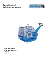
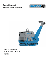
Page is loading ...

CR 7-II Hd
CR 7-II Hd E
CR 7-II Hd CCD
0116641
0116642
0116645
Operating and
Maintenance Manual

2
1
2
3
4
56
Attached to the machine is a rating plate. Note down the information given on this plate so that you
can recreate the rating plate should the plate be lost.
1 Designation 2 Type
.................................................... ...................................................
3 Serial no. 4 Year of construction
.................................................... ....................................................
5 Weight 6 Rated power kW
.................................................... ....................................................

3
Contents
1. Introduction ..................................................................................................................... 4
2. Description ...................................................................................................................... 5
3. Technical data ................................................................................................................. 6
4. Safety ............................................................................................................................... 7
4.1. Information and safety stickers ........................................................................... 12
5. Operation....................................................................................................................... 13
6. Transport ....................................................................................................................... 22
7. Storage .......................................................................................................................... 22
8. Maintenance .................................................................................................................. 23
8.1. Maintenance overview .............................................................................................. 24
8.2. Description of the maintenance operations............................................................ 25
8.2.1. Check the engine oil level ................................................................................ 25
8.2.2. Change the engine oil ...................................................................................... 25
8.2.3.Cleantheairlter ............................................................................................. 26
8.2.4. Check the hydraulic oil level ............................................................................ 27
8.2.5. Change the oil in the exciter ............................................................................ 27
8.2.6. Adjust / replace the spark plug ......................................................................... 27
8.2.7. Check V-belt ..................................................................................................... 28
8.2.8. Use a permanent charger ................................................................................ 28
8.2.9. Change the fuses ............................................................................................. 28
8.3. Operating uids and ll levels ................................................................................. 29

4
This operating and maintenance manual is designed to help
you become familiar with your soil compactor and enable you
to maintain it and use it for its intended purpose.
The safety and maintenance instructions provided in this
manual will help avoid hazards, reduce repair and downtime
costs and will increase the reliability and operational readiness
of your machine. Follow these instructions precisely.
This operating and maintenance manual must always be kept
at the implementation site of the machine and be available to
the machine operator.
If you require any additional information, turn to your
Weber MT dealer.
Found on the last page of this manual is a QR code. Scan
it to acquire the current contact addresses of all Weber MT
branches.
You can obtain information on the assembled Honda gasoline
engine and the associated operating and maintenance manual
as well as the spare parts list, if needed, at
www.honda-engines-eu.com
You can obtain the current spare parts list of the machine in
the WeberMT Service App or use the link below:
1. Introduction
https://www.webermt.com/DE/deu/ersatzteillistenspare-partscr-6-cr-9/cr-7/

5
2. Description
The machine The machine is a hand-guided, reversible soil compactor.
The machine is composed of a bottom and a top section.
The bottom section houses the exciter, while the top section
contains the engine and the required controls.
An air-cooled Honda gasoline engine makes the exciter vibrate
via a centrifugal clutch. The generated force is transmitted
between top and bottom section via a V-belt.
The engine speed is adjusted between idle speed and full-
throttle speed via a gas lever.
Forward and reverse travel is variably controlled with a handle
via a hydraulic system.

6
3. Technical data
CR 7-II Hd CR 7-II Hd E CR 7-II Hd CCD
Weight
Operating weight CECE [kg] 397 423 425
Dimensions
Overall length [mm] 1710 1710 1710
Overall width/with attachment plates
[mm] 510/650/790 510/650/790 510/650/790
Height with folded guide bar [mm] 1160 1160 1160
Base plate length [base in mm] 450 450 450
Pressure surface [mm] 450x640/450x790 450x640/450x790 450x640/450x790
Drive
Engine manufacturer Honda Honda Honda
Type GX390 GX390 GX390
Performance at operating speed in ac-
cordance with ISO 3046-1 [kW] 6.4 6.4 6.4
Combustion process 4-stroke gasoline 4-stroke gasoline 4-stroke gasoline
Operating speed [1/min] 2750 2750 2750
Operating speed [soil-dependent,
m/min] 24 24 24
Incline capacity [soil-dependent, %] 35 35 35
Vibration
System Two-shaft vibrator Two-shaft vibrator Two-shaft vibrator
Drive concept mechanical mechanical mechanical
Frequency [Hz] 74 74 74
Centrifugal force [kN] 65 65 65
Noise emissions in accordance with
2000/14/EC
Sound pressure level LPA ascertained
in accordance with EN 500, [dB (A)] 94 94 94
Sound power level LWA ascertained in
accordance with EN ISO 3744 and EN
500, [dB (A)]
108 108 108
Vibration values
Root-mean-square acceleration value
for hand-arm vibration ascertained in
accordance with EN 500, [m/s²]
2.1 2.1 2.1
In accordance with directive 2006/24/
EC, complying with the vibration values
is the owner's responsibility

7
4. Safety
General All safety instructions must be read and complied with, as non-
compliance will result in
- Danger to life and limb of the user,
- Impairments to the machine or other property.
In addition to the operating manual, the accident-prevention
regulations in the country where the appliance is used must be
complied with.
Intended use
Non-intended use
Residual risk There is always an increased risk of accidents in the
immediate danger area around the machine if the operator
fails to notice persons in the vicinity of the machine.
Anyone close to the machine must be made aware of this risk.
The operator must not put the machine into operation unless
everyone in the vicinity of the machine is aware of this risk.
The machine should only be used in technically faultless
condition, as intended, in a safety-conscious and hazard-
conscious manner, and in compliance with the instructions in
the operating manual.
Malfunctions that may impair safety require that you stop
working with the machine immediately. These types of damage
must be reported and corrected without delay.
The machine is designed exclusively for compacting:
- Sand,
- Gravel,
- Crushed rock,
- Low-cohesive mixed material,
- Paved surfaces.
The operator's work position is behind the machine.
The operator must guide the machine safely with both hands
on the handle.
Unless used as intended, the machine involves a risk of
personal injury and property damage. The machine is
expressly not suitable for:
- Compacting frozen subsurfaces,
- Compacting hard soils that cannot be compacted
further,
- Compacting non-bearing material,
- Compacting highly cohesive soils,
- Compacting (ramming) that exerts point loads on the
base plate,
- Crushing and compacting individual rocks.
The responsibility for any damage arising from non-intended
use falls on the owner / operator.
Non-intended use or misuse will void all liability and warranty
claims.

8
Requirements on the operator
Personal protective equipment Personal protective equipment consisting of
- Hard hat,
- Hearing protection,
- Protective gloves,
- Work shoes or boots with toe guard
must be worn during operation and the execution of
maintenance on the machine.
Danger areas The immediate danger area is the direct perimeter around the
machine.Thisareaiso-limitstothirdparties.
Spare parts, changes and
conversions
Changes and conversions are prohibited unless made with
originalWeberMTspareparts.Ifthemachineismodied
with other accessories without the approval of Weber MT, the
manufacturer will not assume liability for any resulting personal
injury or property damage.
All maintenance and repairs must be carried out with original
WeberMTspareparts.Untestedsparepartsmayaectthe
reliability and safety of the machine.
Before starting the machine There is danger of material damage if the machine is
started before necessary maintenance or repairs have been
completed. Make sure every time before starting the machine
that all work on the machine has been completed.
To avoid injuries, the machine must not be started unless the
operator wears the required personal protective equipment.
Objectsplacedontopofthemachinemayfallorbeungo
during operation or when the machine is started. Therefore,
remove all loose objects or tools before starting the machine.
If the gas cap is open, fuel may escape and ignite on the
engine when the machine is started or while it is operating.
There is a risk of burns. Therefore, do not start the machine
unless the gas cap is closed.
This soil compactor may only be operated by suitable
operators who are 18 years or older. They must be instructed
on how to operate the machine by the owner or by the owner's
assignedpersonnel.Theoperatormustcomplywithtrac
regulations.
The machine must not be operated by children.

9
Start-up procedure Do not disperse any sprays or other agents into the air intake
while the machine is starting up. They may lead to overheating
in the combustion chamber and result in damage to the
engine.
Thereisdangerofsuocationiftheoperatorstartsupthe
machine in closed rooms or in deep and tight trenches.
Operating the machine in closed rooms is prohibited. Provide
for an adequate supply of air before starting the machine.
One electronic start procedure must not last longer than 5
seconds to avoid damage to the engine. Pause for at least 10
seconds before repeating the start procedure.
If the ignition key fails to spring back to position “1” by itself,
the electric starter and the engine may sustain damage. Abort
the start procedure and shut down the machine. Identify and
rectify the cause before the next start attempt.
During operation Monitor the surroundings to avoid injury to third parties or
material damage.
Suspend operation and shut down the machine if detecting
damage on the machine during operation.
Stop operation and shut down the machine if the light
indicators of the start module do not go out shortly after startup
or come on during operation.
The symbol is lit permanently during operation. It signals
that the engine is running. Refer to the section “Operation” for
the exact meaning of the individual light indicators.
Parking the machine Alwaysparkthemachineonalevelsubsurfacewithsucient
bearing capacity.
Parked machines presenting an obstacle must be secured in
accordance with statutory regulations, particularly in the area
ofpublictracsurfaces.
Engine and exhaust heat up during operation and can cause
burns on contact. Therefore, do not touch these components
duringoperationorshortlyafterthemachinewasswitchedo.
Fueling the machine Spilled fuel may ignite and has a negative impact on the
environment. Therefore, wipe up spilled fuel and make sure
thegascapisrmlytightenedafterfueling.

10
Cleaning work Useclearwaterforcleaning.Donotuseammablesolvents.
The vapors of the solvents may ignite upon contact with hot
components or other sparks.
Perform cleaning tasks only in rooms that are suitable and
have been approved for that purpose. Residual oil and
lubricantsthatmayhavebeenrinsedohaveanegative
impact on the environment and must be collected by suitable
means (e.g. oil separator).
Safe handling of combustion
engines
Combustion engines pose a particular risk during operation.
Their exhaust emissions contain carbon monoxide, a colorless
and odorless gas that is extremely hazardous, which, if inhaled
evenbriey,cancauseunconsciousnessanddeath.
Therefore, never inhale the exhaust gas.
Inspection The machine must be inspected in accordance with the
corresponding implementation conditions and operating
conditions to ensure its operationally safe status. This
inspection should be performed as needed by an expert
-however,nolessthanonceayear.Thendingsofthe
inspection must be stored in writing until the time of the next
inspection.
When coming into contact with fuels, the rubber-bonded metal
buersofthemachinemaybecomedamagedorineective.
Therefore,wipespilledfuelcarefullyotherubber-bonded
metalbuers.
Fuelvaporsareeasilyammable.Donotsmokeandkeep
awayfromopenrewhilerefuelingthemachine.
The machine must not be fueled unless the engine is switched
o.

11
Safety instructions and
warnings
A variety of safety instructions and warnings are used
throughout this operating manual.
The following explains the meaning of signal words and
symbols.
ATTENTION warns of the
danger of material dam-
age.
CAUTION warns of the
danger of slight injury.
WARNING warns of a dan-
ger that may lead to death
or serious injury.
DANGER warns of a dan-
ger that will lead to death
or serious injury unless
avoided.
ATTENTION
CAUTION
WARNING
DANGER
The information symbol provides supplemental
information on the operation of the machine and
points to complementary technical information.

12
4.1. Information and safety stickers
Sticker Meaning
1
All threaded unions must be
checkedforrmseatonaregular
basis and, particularly, after initial
use.
2The fuel tank may only be fueled
with regular gasoline.
3Turn the gas cap to open and
close it.
4
Use the designated lifting ring to
lift the machine.
Sound power level 108 dB (A),
Wear ear protection.
5*
When disconnecting the engine
bracket from the base plate,
make sure not to damage the
sensor cable.
The sensor must be detached
from the base plate.
*Only units equipped with COMPATROL compaction control.

13
5. Operation
Preparing the machine for
initial use
Remove all packaging material.
Check all components for visible damage. Do not start
the machine if detecting visible damage. Contact the
responsible dealer.
Check if the shipment of the machine and its components is
complete.
Checkthellleveloftheoperatinguidsandtopoif
necessary.
Set up the machine at its place of use.

14
1
2
3
4
5
6
7
8
910
Operating positions on the machine
Overall view CR 7
1 Base plate with exciter
2 Mounting bracket
3 Gas lever
4 Handle
5 Guide bar
6 Lifting ring
7 Engine
8* Key switch
9* Start module
10** Compaction control system Compatrol
*Only CR 7-II Hd E and CR 7-II Hd CCD
**Only units equipped with COMPATROL compaction control.
Figure 1

15
5
1
2
4
3
The start module
MS 15
1 Operational status indicator
(LED)
This indicator signals that the ignition of the machine is
switched on. It comes on as soon as the key switch (5) is set
to position “1”.
2 Oil pressure indicator (LED) Thisindicatorwarnsofinsucientoilpressure.
Shut down the machine immediately when this indicator comes
on.
3 Operating hours counter Thiseldshowstheoperatinghourscompletedbythe
machine.
The counter will show the remaining time until the next
scheduledmaintenancefortherst10secondsafterthe
ignition was switched on (key switch (5) in position “1”).
4 Charge level indicator (LED) This indicator comes on if the charging current supply to the
starterbatteryisinsucient.Whileoperationofthemachine
canresume,thecauseoftheinsucientchargingcurrent
supplymustbeidentiedandrectied.
5 Key switch The key switch is used to switch the power supply (ignition) to
themachineonoro.Italsoactuatestheelectricstarterofthe
engine.
Switch in position “1”
The ignition is switched on.
Switch in position “0”
Theignitionisswitchedo.
Switch in position “2”
The electric starter is actuated.
Danger of material damage from running electric starter.
The ignition key must spring back from position “2” to position
“1”. Otherwise:
Shut down the machine immediately.
Figure 2
ATTENTION

16
1 3
2
1 Operational status indicator
(Green)
This indicator comes on as soon as the correct operating
frequency has been reached and signals that the compaction
control system is operational.
Aashingoftheindicatorsigniesthatthemachineisworking
with an incorrect operating frequency.
2 Compaction indicator
(Yellow)
The LEDs 1-7 indicate the achieved compaction of the soil.
The number of lit LEDs rises with the increasing compaction.
If no additional LED comes on after another pass over the
same spot, the maximum level of compaction has been
reached.
3 Warning light (Red) The warning light comes on prior to operation if soils are too
hard.
Such soils cannot be compacted with the machine type used
and may cause damage to the machine.
The COMPATROL compaction control system
Figure 3

17
Possible indicator states
Function test of the LEDs A function test of the LEDs is performed when the ignition is
turned on, but the engine has not yet been started.
The operational status indicator (1) and the warning light (3)
light up permanently.
The LEDs of the compaction indicator (2) light up in
succession from left to right and go out in reverse order.
After engine start, before
reaching the operating
frequency
The warning light (3) signals by lighting up permanently that
the compaction indicator is not operational yet.
The LEDs of the compaction indicator (2) are not yet lit.
Theoperationalstatusindicator(1)signalsbyashingthatthe
operating frequency has not been reached yet.
The attainable maximum may vary with the type and composition of the
soil. On sand, the maximum is commonly reached at a low number of lit
LEDs.
Following the compaction of a mix of gravel and crushed rock that is
uniformly graded and contains the proper concentration of water, the
indicator is likely to show six to seven lit LEDs.
It is important to closely monitor the indicator during the last pass. Places
where the number of lit LEDs drops sharply are poorly compacted. In
these places, the soil needs to be compacted again or may even have to
be replaced.
Reaching the operating
frequency, operation
Upon reaching the operating frequency, the operational status
indicator (1) lights up permanently, indicating that the machine
is ready for operation.
The warning light (3) goes out.
The compaction indicator (2) starts lighting up, indicating the
achieved level of soil compaction.
Illumination of the warning
light
The warning light comes on prior to operation if soils are too
hard.
If all LEDs of the compaction indicator (2) are lit together with
the warning light (3), the soil to be compacted is too hard.
Stop operation immediately to avoid damage to the machine.

18
1
2
3
Before starting work
Perform the following tasks before starting to work in order to
prevent failures or excessive wear.
Visual inspections Hydraulic line for leaks
Fuel system for leaks
Rubberbuersforcrackformation
Other damage
Check and, if necessary,
correct the ll levels
Engine oil
Hydraulic oil
Fuel
Other inspections Checkallthreadedunionsforrmseat
Verify compliance with the maintenance schedule
Figure 4
1* Vandalismap
2* Valve box
3 Set screw
*Only CR 7-II Hd E and CR 7-II Hd CCD

19
Adjust the desired work height of the guide bar with the set
screw(position3,gure4).
Openthevandalismap(position1,gure4).
Insertthevandalismap(1)intothedesignatedholderon
thevalvebox(position2,gure4).
Open the fuel cock (slide to the right).
Close the choke lever (slide to the left).
Bring the gas lever into the full-throttle position “ON”.
Turn the ignition key to position “2” and hold it until the
engine turns over.
Release the ignition key as soon as the engine is running.
ATTENTION! Danger of material damage from running
electric starter.
The ignition key must spring back to position “1”
automatically. Otherwise, shut down the machine
immediately.
Set the gas lever to the idle speed “STOP”.
The operational status indicator signals that the machine
is ready for operation.
Allow the engine to warm up for a few minutes.
Open the choke lever (slide to the right).
ATTENTION
Risk of engine damage if start procedures take too long.
One start procedure must not be longer than 5 seconds. Pause
for at least 10 seconds before repeating the start procedure.
WARNING
Dangerofsuocationfromengineexhaustswhenstartingthe
engine in closed rooms or poorly ventilated work areas.
Start the engine only in well-ventilated environments.
See section “Safety” for operating the machine in trenches.
ATTENTION
Risk of engine damage. The use of starter spray may lead to
overheating in the combustion chamber.
Do not use any starter spray.
Working with the machine
Starting the engine
CR 7-II Hd E & CR 7-II Hd CCD

20
CR 7-II Hd
1
3
2
Adjust the desired work height of the guide bar with the set
screw (1).
Set the short-circuit switch (2) to “I”.
Open the fuel cock (slide to the right).
Close the choke lever (slide to the left).
Bring the gas lever into the full-throttle position “ON”.
Slowly pull the handle of the reversing starter (3) until
resistance (the compression of the engine) is noticeable.
Allow the handle to glide back into the initial position.
Pull the handle through quickly, forcefully and completely.
Repeat the process if the engine does not start.
Set the gas lever to the idle speed “STOP”.
Allow the engine to warm up for a few minutes.
Open the choke lever (slide to the right).
The machine is ready for operation.
Figure 5
/
