Page is loading ...

ROTOLINE
RLI 700 FC
RLI 900 FC
RLI 1200 FC
RLI 1600 FC
RLI 2000 FC
RLI 700 EC
RLI 1200 EC
RLI 1600 EC
RLI 2000 EC
ROTO KOMPAKT
ROTO K 1050 H
ROTO K 1700 H
ROTO K 2800 H
ROTO K 4200 H
ROTO K 7600 H
ROTO K 12600 H
Assembly and Operating Manual
English
www.ruck.eu

2
English
Tel. +49 7930 9211-0 Fax +49 7930 9211-150
Information updated: print 08.03.2022
We reserve the right to make changes
The data specied above only serve to describe the product. No
statements concerning a certain condition or suitability for a cer-
tain application can be derived from our information. The informa-
tion given does not release the user from the obligation of own
judgment and verication.
It must be remembered that our products are subject to a natural
process of wear and aging.
This document, as well as the data, specications and other in-
formation set forth in it, are the exclusive property of ruck Ven-
tilatoren GmbH.
It may not be reproduced or given to third parties without its con-
sent.
The picture on the cover shows an example conguration. The
product supplied may therefore differ from the illustration.
The original manual has been pro-
duced in the German language.
mwr_rok_h_pb_06_k10001_en print 08.03.2022
ruck Ventilatoren GmbH Max-Planck-Str. 5 D-97944 Boxberg-Windischbuch Tel. +49 7930 9211-0 Fax +49 7930 9211-150 [email protected]

3
English
Assembly and Operating Manual
Contents 1. Important information ............................................................................. 5
1.1. Rules and regulations .................................................................... 5
1.2. Guarantee and liability .................................................................. 5
2. General safety instructions .................................................................... 5
2.1. Intended use .................................................................................. 5
2.2. Improper use .................................................................................. 6
2.3. Personnel qualications ................................................................. 6
2.4. Safety instructions in this manual ................................................... 6
2.5. Adhere to the following instructions ............................................... 7
2.5.1. General instructions ....................................................................... 7
2.5.2. During installation ........................................................................... 7
2.5.3. During commissioning .................................................................... 7
2.5.4. During operation ............................................................................. 7
2.5.5. During cleaning .............................................................................. 7
2.5.6. During maintenance and repair ...................................................... 7
2.5.7. Disposal ......................................................................................... 7
2.6. Safety labels on the product ........................................................... 8
3. Delivery contents ..................................................................................... 9
4. Product and Performance description .................................................. 9
4.1. Device description .......................................................................... 9
5. Transport and storage ........................................................................... 11
6. Assembly ................................................................................................ 11
6.1. Permitted installation positions ..................................................... 12
6.2. Duct connections .......................................................................... 12
6.3. Application limits .......................................................................... 12
6.4. Medium connections / Heating Coil .............................................. 12
6.5. Condensate drainage ................................................................... 13
6.6 Ball siphon installation .................................................................. 13
7. Electrical connection ............................................................................ 13
7.1. Overcurrent protection ................................................................. 14
7.2. Description external inputs and outputs ....................................... 15
8. Commissioning ...................................................................................... 16
9. Operation ................................................................................................ 17
9.1. Control unit ................................................................................... 17
9.2. Menu functions ............................................................................ 17
9.3. Changing setpoint temperature and fan steps ............................. 18
9.4. General value changing ............................................................... 18
9.5. Adjustment of the control unit parameter .................................... 19
9.5.1. Language settings ....................................................................... 19
9.6. Display user level ......................................................................... 20
9.7. Menu level Operating parameters (qualied personnel) ROTO K ...
22
9.7.1. Control type ROTO K-S: Constant volume ow control ............... 22
9.7.2. Control type ROTO K-P: Constant pressure control .................... 27
9.7.3. Control type ROTO K-PV: Constant pressure control with balanced
air volume ................................................................................................ 28
9.8. Menu level Commissionning ROTO K ........................................ 31
www.ruck.eu

4
English
Tel. +49 7930 9211-0 Fax +49 7930 9211-150
9.9. Time / Time switch ........................................................................ 33
9.9.1. Setting the current time / day ....................................................... 33
9.9.2. Setting the timer ........................................................................... 34
9.9.2.1. Timer on and off switching .......................................................... 34
9.9.3. Setting day - night switch-over ..................................................... 35
9.9.4. System drawings .......................................................................... 36
9.10. Functions ...................................................................................... 37
9.10.1 Fan error message contact .......................................................... 37
9.10.2 Hot water coil .............................................................................. 37
9.10.3 Version with electric heating coil .................................................. 37
10. Maintenance and repair ........................................................................ 37
10.1. Important notes ............................................................................ 37
10.2. Cleaning and care ........................................................................ 38
10.3. Maintenance ................................................................................. 38
10.3.1. Rotating wheel heat exchanger .................................................... 38
10.3.2. Belt drive for rotating wheel .......................................................... 38
10.3.3. Air lter ......................................................................................... 39
10.3.4. Changing the battery .................................................................... 40
11. Modbus communication interface ....................................................... 41
11.1. Wiring diagram ............................................................................. 41
11.2. Interface information .................................................................... 41
11.3. Functions implemented ................................................................ 41
11.4. Parameter table ........................................................................... 42
11.5. Current value table ...................................................................... 44
12. Expansionandreconguration ............................................................ 45
13. Dismantling and disposal ..................................................................... 45
13.1. Disassembling the product ........................................................... 46
13.2. Disposal ....................................................................................... 46
14. Troubleshooting ..................................................................................... 46
14.1. Low-current fuses ......................................................................... 46
14.2. Fault diagnosis chart .................................................................... 46
15. Technical data ........................................................................................ 50
16. Appendix ................................................................................................ 52
16.1. List of parameters ........................................................................ 52
16.2. Technical drawings ....................................................................... 53
16.3. Wiring diagrams .......................................................................... 59

5
English
The ruck air handling unit is a component in terms of the machine directive 2006/42/EC (partly
completed machinery). The product is a not ready-for-use machine in terms of the machine directive.
It is intended exclusively for installation in a machine or in ventilation equipment and installations or
for combination with other components to form a machinery or installation. The product may be com-
missioned only if its integrated in the machinery/system for which it is designed and the machinery/
system fully complies with the EC machinery directive.
Observe the operating conditions and performance limits specied in the technical data.
ruck ventilation products can be used to provide:
• Clean, dry air (no condensation) and non-aggressive gases with a maximum density of 1.2 kg/
m³.
• Outside air and supply air
• The medium and room temperatures and the humidity range given in the technical data and on
the rating plate.
Intended use includes having read and understood these instructions, especially chapter 2 “General
safety instructions”.
1. Important information
This manual contains important information on the safe and appropriate assembly, transport, commission-
ing, operation, maintenance, disassembly and simple troubleshooting of the product.
The product has been manufactured according to the accepted rules of current technology.
There is, however, still a danger of personal injury or damage to equipment if the following general safety
instructions and the warnings before the steps contained in these instructions are not complied with.
• Read these instructions completely and thoroughly before working with the product.
• Keep these instructions in a location where they are accessible to all users at all times.
• Always include the operating instructions when you pass the product on to third parties.
1.1. Rules and regulations
1.2. Guarantee and liability
Also observe the generally applicable, legal or otherwise binding regulations of the European or
national legislation and the rules for the prevention of accidents and for environmental protection
applicable in your country.
ruck products are made to the highest technical standards in accordance with the generally rec-
ognized rules of the profession.
They are subject to constant quality control and meet the relevant
requirements when delivered. Because the products are being constantly developed, we reserve the
right to make changes to the products at any time and without prior announcement. We do not accept
any liability for the correctness or completeness of this installation and operating manual.
Thewarrantyonlyappliestothedeliveredconguration. The warranty will not apply if the product
is incorrectly assembled or handled or not used as intended.
2. General safety instructions
2.1. Intended use
• Exclusively use ruck air handling units in good technical order and condition.
• Check the product for visible defects, for example cracks in the housing or missing rivet, screws and
covers.
• Only use the product within the performance range provided in the technical data.
• Protection against contact and being sucked in and safety distances should be provided in accor-
dance with DIN EN 13857.
• Generally prescribed electrical and mechanical protection devices are to be provided by the client.
• Safety components must not be bypassed or put out of operation.
• The product may be operated by personnel with limited physical, sensory or mental capacities only if
they are supervised or have been instructed by responsible personnel.
• Children must be kept away from the product.
Planners, plant engineers and operators are responsible for ensuring that the product is installed and
operated correctly.
www.ruck.eu

6
English
Tel. +49 7930 9211-0 Fax +49 7930 9211-150
Any use of the product other than described in chapter “Intended use” is considered as improper.
The following points are improper and dangerous:
• Delivery of explosive and flammable media or operation in potentially explosive atmospheres.
• Delivery of aggressive and abrasive media.
• Delivery of media containing dust or grease.
• Installation outside without any protection against the weather.
• Installation in wet areas.
• Operation without the duct system.
• Operation with closed air connections.
2.2. Improper use
Assembly, commissioning,operation, disassembly and service (including maintenance and repair)
require basic mechanical and electrical knowledge, as well as knowledge of the appropriate tech-
nical terms. In order to ensure operating safety, these activities may therefore only be carried
out by qualied technical personnel or a person under the direction and supervision of qualied
personnel. Qualied personnel are those who can recognize possible hazards and institute the
appropriate safety measures due to their professional training, knowledge, and experience, as
well as their understanding of the relevant conditions pertaining to the work to be done. Qualied
personnel must observe the rules relevant to the subject area.
2.3.Personnelqualications
In this manual, there are safety instructions before the steps whenever there is a danger of per-
sonal injury or damage to the equipment. The measures described to avoid these hazards must
be observed.
2.4. Safety instructions in this manual
Safety instructions are set out as follows:
Safety sign (warning triangle) - Draws attention to the risk.
• Type of risk! - Identies the type or source of the hazard.
» Consequences
- Describes what occurs when the safety instructions are not complied with.
→ Precautions - States how the hazard can be avoided.
General warning!
Indicates possible hazardous situations. Failure to observe the warn-
ings may result in personal injury and / or damage to property.
Electricity warning (hazardous voltage)!
Indicates possible hazards due to electricity. Failure to observe the warn-
ings may result in death, injury and/or damage to property.
Hot surface warning!
Indicates possible hazards due to high surface temperatures. Failure
to observe the warnings may result in personal injury and/or damage to
property.
Crushingofngerswarning!
Indicates possible hazards due to moving and rotating parts. Failure to
observe the warnings may result in personal injury.
Overhead load warning!
Indicates possible hazards due to overhead loads. Failure to observe the
warnings may result in death, injury and/or damage to property.
Important instructions follow!
Instructions for safe, optimum use of the product.
Safety sign
(warning
triangle) Consequence

7
English
2.5. Adhere to the following instructions
• Observe the provisions for accident prevention and environmental protection for the country
where the product is used and at the workplace.
• Persons who assemble, operate, disassemble or maintain ruck products must not consume
any alcohol, drugs or pharmaceuticals that may affect their ability to respond.
• Responsibilities for the operation, maintenance and regulation of the product should be clearly
determined and observed so that there can be no unclear areas of responsibility with regard to
safety.
• Never overload the product. Never use it as a handle or step. Do not place anything on it.
• The warranty only applies to the delivered configuration.
• The warranty will not apply if the product is incorrectly assembled or handled or not used as
intended.
2.5.1. General instructions
2.5.2. During installation
• Disconnect all of the product‘s poles from the mains before installing the product or connecting
or removing plugs. Make sure that the product cannot be switched back on again.
• Lay cables and lines so that they cannot be damaged and no one can trip over them.
• Before commissioning, make sure that all gaskets and seals in the plug-in connections are cor-
rectly fitted and undamaged in order to prevent fluids and foreign matter getting into the product.
• Information signs must not be changed or removed.
• Make sure that all electrical connections are either used or covered. Commission the product
only if it is installed completely.
• The power switch must be always fully functional and easy accessible!
2.5.3. During commissioning
2.5.4. During operation
• Only authorized personnel is allowed to operate the setting mechanisms of the components or
parts, under the provision that the system is used as intended.
• In an emergency, or if there is a fault, or other irregularities, switch the equipment off and make
sure it cannot be switched back on again.
• The technical data given on the rating plate must not be exceeded.
2.5.5. During cleaning
• Never use solvents or aggressive detergents. Only clean the product using a slightly damp, lint-
free cloth. Only use water to do this and, if necessary, a mild detergent.
• Do not use a high-pressure cleaner for cleaning.
• After cleaning, make sure that the product is working correctly again.
2.5.6. During maintenance and repair
• If operated correctly, ruck products only require a minimum amount of maintenance. Please
follow all of the instructions given in section 10 in this respect.
• Make sure that no connections or components are loosened unless the device is disconnected
from the mains. Make sure that the equipment cannot be switched back on again.
• Individual components must not be interchanged. For example, the components intended for
one product may not be used for other products.
2.5.7. Disposal
• Dispose the product in accordance with the currently applicable national regulations in your
country.
www.ruck.eu

8
f
f
1
2
F7
F5
M5
f
f
1
2
F7
F5
!
!
i
!
!
!
!
!
!
!
!
i
F7
F5
1.
°C
f
f
2
1
!
i
F7
F5
1.
°C
f
f
2
1
!
i
F7
F5
1.
°C
f
f
2
1
139918
!
i
M5
F7
!
!
!
!
English
Tel. +49 7930 9211-0 Fax +49 7930 9211-150
2.6. Safety labels on the product
(*Optinal depending on the type.)
Air lter (Panel Filter)
Filter class F7
Air lter (Panel Filter) Filter
class M5
Connection condensate drain-
age
Heat exchanger (rotating heat
exchanger)
Read the operating manual be-
fore commissioning the product
Connections for the heating coils
Connections for cooling or
DX-Coil
• Electricity warning (hazardous voltage)!
»Failure to observe the hazard may result in death,
injury or damage to property.
→Before performing any work on conductive parts, always
disconnect the unit completely from the electricity supply
and make sure that it cannot be switched back on again.
• Never reach into the impeller or other rotating or
moving parts.
»Failure to observe the hazard may lead to serious
injury.
→Work may only be performed once the impeller has
come to a complete halt.
• Never clean the internal space with owing water or a
high-pressure cleaner. Do not use aggressive or easily
ammable products for cleaning (impellers/housing).
→Only use mild suds. The impeller should be cleaned
with a cloth or brush.
• General warning
»Failure to observe the warnings may result in personal
injury and / or damage to property.
→Unauthorized repairs may cause personal injury and /
or damage to property, in which case the manufactur-
er’s guarantee or warranty will not apply.
• Caution! Burning hazard.
»Failure to observe the hazard may result in personal
injury and/or damage to property.
→Do not touch the surface until the motor and heater
have cooled.
• Never reach into rotating or moving parts.
»Failure to observe the hazard may lead to serious
injury.
→Work may only be performed once the impeller has
come to a complete halt.

9
3
7
6
1
5
2
2
4
11
12
910
8
13
Idx
TeileId
14
15
English
4.1. Device description
3. Delivery contents
Included in delivery depending on model type:
• 1 x ROTO KOMPAKT H, air handling unit
• 1 x remote control with control cable
• 1 x installation and operating manual
4. Product and Performance description
The ROTO K is a ventilation device with integrated rotating heat exchanger for optimum heat and mois-
ture recovery. Integrated in the device are large compact filters M5 / F7, two EC fans, supply and extract,
hot water re-heater and integrated control. Another cooling or DX-coil can also be fitted as an option.
The device has a remote control for controlling and setting the operating parameters. The high quality
housing consists of a frameless sheet metal structure with smooth internal and external walls. The hous-
ing is insulated with 40 mm mineral wool. The unit can be operated at a constant volume. Control using
external sensors provides the appropriate ventilation.
Data in detail:
• Frameless housing made from galvanised steel, without cold bridges.
• Extractable rotating heat exchanger with belt drive.
• Hot water re-heater
• Extractable large panel filters M5 / F7.
• Controller installed, wired, ready to plug in.
• Integrated isolator switch.
• External control unit with control cable.
• Optionally with cooling or DX-Coil.
• Maximum temperature: 40 C° (s. technical data).
• Protection class: in ceiling installation correct duct and cable connection, IP 43 (see connection
diagram).
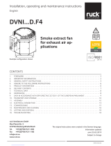
Legend
1. Housing
2. Door
3. Isolator switch
4. Door handle with lock
5. Socket
6. EC centrifugal fan
7. Cable glands
8. Rating plate
9. Connection cooling / DX-Coil
10. Connection heating coil
11. Connection supply air
12. Connection extract air
13. Connection condensate drainage
14. Remote control
15. Remote control cable
(*Optinal depending on the type.)
Fig. 1:
Typ: ROTO K ... H
www.ruck.eu

10
17
1
16
18
22
30
31
19
12
21
13
23
2
25
26
20
27
28
13 5
24
6
1
29
139918
!
i
M5
F7
English
Tel. +49 7930 9211-0 Fax +49 7930 9211-150
Legend
16. Heating coil / Heater
17. Cooling* / DX-Coil*
18. Frost protection controller
19. Supply air temperature sensor
20. Drip tray
21. Controller board
22. Safety labels
23. Cover for terminal box
24. Terminal Box Duct
25. Extracted air temperature sensor
26. Air lter M5 - extract air
27. Rotating heat exchanger
28. Air lter F7 - supply air
29. Intermediate oor
30. Connection intake air
31. Connection exhaust air
Units / Model:
ROTO K ... H
Fig. 2:
Typ: ROTO K ... H
(*Optinal depending on the type.)

11
English
Fig. 3:
Unit transported on a pallet with
a forklift.
5. Transport and storage
6. Assembly
Transport and storage should only be performed by specialist personnel in accordance with the installation
and operating manual and regulations in force.
The following points should be noted and followed:
• Check the delivery according to the delivery note to ensure it is complete and correct and check for
any damage. Any missing quantities or damage incurred during transport should be confirmed by the
carrier. No liability is accepted if this is not observed.
• The product weighs approx. 200 - 750 kg (depending on the product type in question).
For weight see technical data
• It should be transported with suitable lifting equipment in the original packaging or on the transport
equipment indicated.
• If transported with a forklift it should be ensured that the product is resting with the basic profile or
base frame completely on the forks or on a pallet and the product‘s centre of gravity is between the
forks (see Fig. 3).
• The driver must be authorized to drive a forklift.
• Do not go beneath the suspended load.
• Only lift and transport the machine by its base plate, never by the cover handle!
• Avoid damage or deformation of the housing.
• The product must be stored in a dry area and protected from the weather in the original packaging.
Open pallets should be covered with tarpaulins. Even weatherproof modules should be covered
because their weather resistance is only guaranteed after complete installation.
• Storage temperature between –10 °C and +40 °C. Avoid severe temperature fluctuations.
• If the product has been in storage for more than a year, check the smooth running of impellers and
valves by hand.
Assembly work may only be performed by specialist personnel in accordance with the installation and
operating manual and the regulations and standards in force.
The following points should be noted and followed:
• The foundation must be even and levelled. It must not exhibit unevenness or a slope in any direction.
• Suitable foundations are: full foundation in concrete, strip foundations or steel bearer structures. In the
case of strip foundations and steel structures, it must be ensured that the machine base sits fair and
square on the bearers. Steel structures must be sufficiently rigid for the size of the machine.
• Set up and align the machine with the aid of a water level. Only if the machine is horizontally installed
can proper condensate drainage be guaranteed.
• Only suitable installation aids, in accordance with regulations, should be used.
• The installation should be easily accessible for maintenance and cleaning and should be easy to
dismantle.
• The unit should only be installed with authorized and suitable fastening materials at all fastening
points.
• Do not distort the unit when installing.
• The unit should be suitably secured.
• No holes should be made in the housing, or any screws screwed into it.
• The duct system must not be supported on the housing.
• It is recommended that the duct system is attached with flexible connections in order to isolate any
structure-borne noise.
• Make sure that the duct system cannot be closed off.
• Make sure that the intake duct has direct access to the intake air.
Warning: branches in the intake duct, to other fan units for example, may, if the dimensions
are too small, lead to low pressure in the duct and therefore malfunction of the unit.
• The pressure loss in the duct system must not be more than the capacity of the unit! The pressure
loss in the duct should not be more than 2/3 the unit‘s maximum pressure so that an adequate air
output can still be achieved. This will prevent malfunction. Pressure losses in the duct system are ad-
versely affected by: the length of the duct system, small duct cross-section, elbows, additional filters,
valves, etc.
www.ruck.eu

12
--
+
English
Tel. +49 7930 9211-0 Fax +49 7930 9211-150
6.4. Medium connections / Heating Coil
• Before connecting heating coil, the duct system must be thoroughly cleaned.
• Use only permitted sealants (DIN EN 751-2, DVGW tested).
• Water connections as marked on the heat exchanger.
• When making pipe connections to the unit, with screw connections, a wrench, for example, must
be used to hold against the tightening torque.
• The connection must be executed without tension.
• Air bleeding must be done on site.
• All pipes and fittings of the medium connections must be insulated.
Hydraulic circuits
For air conditioning applications, there are three basic circuits:
Bypass circuit
With the bypass circuit, only the hot water is fed to the heating coil. The rest of the water supplied
by the pump bypasses the heating coil. This can lead to a temperature difference between top and
bottom of the heating coil if the ow of water through it is very small. The resulting temperature gra-
dients can lead to false temperature measurements in the duct or to draught effects in the room. The
bypass circuit is usually used in air coolers. In air coolers, the air is partly cooled below the dew point
and thereby dehumidied.
Admixture circuit
In the admixture circuit, the circulating pump always supplies the full amount of water required by the
heating coil with an amount of hot water determined by the valve setting. The temperature is thus
constant over the whole heating surface. The temperature control is thus much better. Furthermore,
the risk of frost damage when the pump is running is reduced as the continuous circulation and in-
creased pressure reduce the freezing point of the water.The only advantage of the bypass circuit over
the admixture circuit arises when the pipe lengths between three-way ball valve and water heater are
very long. Because the pump is ahead of the valve, there is always hot water available at the valve
that can be immediately fed to the heat exchanger if required. When in admixture circuit it is possible
the water in the pipe to the valve cools, so when heat is required there is a short delay before the hot
Fig. 5a:
Bypass circuit
Fig. 5b:
Admixture circuit
6.2. Duct connections
Fig. 4:
Connection air duct
6.1. Permitted installation positions
6.3. Application limits
Operating limits indoor installation
Medium: -25 °C to +40 °C
Installation place: min. +5°C
Operating limits outdoor installation
Medium: -25 °C to +40 °C
Installation place: min. -25°C
Outdoor installation only allowed with adequate weather protection.
Extract air class EN 13779 ETA 1 / ETA 2
For the supply and extract ventilation of rooms where the emission sources are human metabolism
or building materials, e.g. ofces, public areas, meeting rooms.
The suitability for enclosure condensation has to be checked by the customer, it is possible that
suitable measures like ventilation of the installation area, or an additional insulation of the outdoor
air intake area, are going to be necessary.
The units must only be mounted upright, connection nozzles horizontal.
The air tubing has to be executed in such a manner that no condensate/rain or snow from the air
duct can enter the unit.
• Insulate cold ducts in warm rooms.
• Insulate warm ducts in cold rooms.
• Using ground heat exchangers in winter is not recommended as it can have negative influence
on the humidity recovery of the unit.
• The duct connection is to be mounted with 4 hexagon bolts (M8 x 20) on the housing.
Use not less than the minimum connection diameters (NS) for the air connections. (see 15. Techni-
cal Data)

13
+
B
C
D
D
E
D-D
English
Fig. 5c:
Injection circuit
6.5. Condensate drainage
• The cooler is equipped with a stainless steel condensate sump.
• A drainage connection from the condensate sump is brought out of the unit.
• To avoid corrosion, the drain pipe from this connection should be in stainless steel, copper or
plastic.
• For units with cold water coil or DX-coil, a siphon must be installed to each drain connection.
• The water seal height in the siphon depends on the pressure inside the unit, the minimum is 60
mm. For internal pressures above 400 Pa, please refer to the water trap heights in Table.
Table: Water seal height
H in siphon as a function
off pressure.
Fig. 6:
Water seal height H
The water seal height can also be determined by calculation, provided the minimum of 60 mm is
maintained:
For hygienic reasons, it is recommended to use the suitable siphon for the unit.
This siphon provides sufcient water seal height and is equipped with a self-closing ball siphon.
The water seal height for on site siphons can also be determined by calculation, provided the
minimum water seal height of 60 mm is maintained.
Legend
Δpst = Static pressure [Pa]
Δpt = Total pressure [Pa]
Δpd = Dynamic pressure [Pa]
H = Water seal [mm]
Example calculation:
Δpst = Δpt - Δpd
Δpst = 500 Pa (see technical data)
1 mm water gauge equals 9,81 Pa
Water seal height H
H = Δpst / 9,81 Pa/mm + 15 mm
H = 500 Pa / 9,81 Pa/mm +15 mm
H = 66 mm
7. Electrical connection
Electrical installation may only be performed by qualied electricians in accordance with the installation and
operating manual and the national regulations, standards and guidelines in force:
• EN, DIN and VDE specifications, including all safety requirements.
• Technical connection conditions.
• Safety at work and accident prevention requirements.
This list does not claim to be complete.
Requirements should be applied under one‘s own personal responsibility.
• The electrical connections must be made as shown in the corresponding wiring diagrams and terminal
diagrams.
• The type of cable, size of cable and method of laying should be determined by an authorized electri-
• Electricity warning (hazardous voltage)!
»Failure to observe the hazard may result in death, injury or damage to property.
→Before performing any work on conductive parts, always disconnect the unit completely from
the electricity supply and make sure that it cannot be switched back on again.
Δ pst [Pa]
H [mm]
300
60
400
60
500
66
600
76
700
86
800
97
water reaches the heating coil.
Injection circuit
The combination of these circuits is the injection circuit, which is generally recommended.
6.6 Ball siphon installation
Fig. 6a: Fig. 6b: Fig. 6c: Fig. 6d:
www.ruck.eu

14
A
A (1 : 5)
1
3
2
4
5 6
English
Tel. +49 7930 9211-0 Fax +49 7930 9211-150
• The unit may only be operated with the correct overcurrent protection.
• This must be established by a qualified electrician.
• The recommended protection is shown in the enclosed wiring diagram..
7.1. Overcurrent protection
cian.
• Low and extra-low voltage cables should be laid separately.
• An all-pole mains disconnection device with at least 3 mm contact gap must be provided in the supply
line.
• Use a separate cable inlet for each cable.
• Any cable inlets that are not used must be sealed so that it is airtight.
• All cable inlets must have strain relief.
• Create equipotential bonding between the unit and the duct system.
• Check all protective measures after the electrical connection work (earthing resistance, etc.)
Connection compartment / Connections on the unit
The connection compartment is inside the unit. You must rst remove the terminal box cover (see Fig. 7).
Every line to be connected must be fed through a separate cable gland and laid in the cable duct provided in
the centre tier of the device (see Fig. 7). Cables that carry mains voltage must be fastened with the tension
relief devices available.
Unit supply cable
Connect the mains supply cable as shown in the wiring diagram. For the dimensioning of the line, observe the
unit‘s rating plate and the relevant guidelines. Suitable fuse protection should be provided.
The extra-low voltage control cables must be laid separately from the mains cables.
Fig. 7:
Connection compartment
(1) Controller board
(2) Cover for terminal box
(3) Cable duct
Fig. 8:
Cable glands
(4) Cable gland power supply
(5) Cable gland sensors / actuators
(6) Cable gland Control unit
Typ Fuse protection
ROTO K 1050 H
3 x 10 A
ROTO K 1700 H
3 x 10 A
ROTO K 2800 H
3 x 16 A
ROTO K 4200 H
3 x 16 A
ROTO K 7600 H
3 x 16 A
ROTO K 12600 H
3 x 16 A

15
English
7.2. Description external inputs and outputs
Unit enabling
The unit can be switched on and off with an external potential-free contact (see wiring diagram). An
external voltage must never be applied to this connection. The control system would be destroyed. Any
devices providing a potential-free contact (e.g. central building control system) can be used to control the
unit. This contact must be securely isolated from interference voltages because otherwise dangerous
conditions might occur in the event of a fault.
The extra-low voltage control cables must be laid separately from the mains cables.
Motion detector
A motion detector can be connected to the controller. When the contact is closed, the device chang-
es to the operating mode „Intermittent ventilation“ with the preset follow-up time according to pa-
rameter 30.
External, potential-free contact.
Circulation pump enable
A circulation pump can be connected to the controller (see circuit diagram). If heating is required,
the heating valve is opened by the controller and the circulation pump output is activated. Any pump
connected must be inherently safe and block-proof.
Electrical connection with Vmax =230 VAC and Imax=2 A.
Fire detector
An external, potential-free re detection contact switches the device off. The display indicates „Error
re protection“. This signals requires a manual reset.
Modbus RTU
The communication interface with Modbus RTU protocol is already integrated as standard. The cen-
tral building control system can be connected directly to the integrated interface via Modbus. Multiple
devices can be connected to the bus with an adapter board as accessory.
The unit can be visualized using the ruck view software software. All parameters, measured and set
values can be controlled by ruck view.
3-way valve heating
Temperature control for the optional warm water heating coil, e.g. active heating to cover the heating
demand by the ventilation system. Control output 3-position control Output 230V.
3-way valve cooling
Temperature control for the optional cold water cooling coil, e.g. active outdoor air cooling by the
ventilation system. Control output 3-position control Output 230V.
0-10V heating / 0-10V cooling
Control output for 3-point control or DX-coil.
Unit malfunction
If there is a malfunction on the unit, an error message appears on the display and at the same time
switches a relay. A closing and opening signal is available (see wiring diagram). Electrical connection
of the changeover contact with U - 230 VAC and Imax = 2A. (There is not any double insulation on the
mains cables).
Frost protection thermostat
An external frost protection temperature thermostat can be connected. As soon as the temperature
drops below the set value, the dampers are closed, the fans are switched off, the circulation pump
is switched on and the heating valve is opened. If the set value is not reached after 20 minutes, the
system switches off completely and the fault message F7 Frost protection appears on the control
panel. The circulation pump remains switched on and the heating valve opened. If the supply air
temperature rises again within 20 minutes, the device returns to normal operation.
P 22 0 = Heating (Water) 0-10V (X15: 5,9) Parallel to the 3-point control heating
1 = Cooling (Water) 0-10V (X15: 5,9) Parallel to the 3-point control cooling
2 = Heating and cooling (Water) If contact Enable Cooling opened, 0-10V heating (X15: 5,9)
If contact Enable Cooling closed, 0-10V cooling (X15: 5,9)
3 = Heating condenser and cooling DX-coil If contact Enable Cooling opened, 0-10V heating (X15: 5,9)
If contact Enable Cooling closed, 0-10V cooling (X15: 5,9)
www.ruck.eu

16
English
Tel. +49 7930 9211-0 Fax +49 7930 9211-150
8. Commissioning
Commissioning by trained technical personnel may only be performed when any risk has been ruled out.
The following checks should be performed in accordance with the installation and operating manual and
the regulations in force:
• Correctly sealed installation of the unit and duct system.
• Check the duct system, unit and medium lines, if present, remove any foreign bodies if necessary.
• The intake opening and inflow into the unit must be clear.
• Check all mechanical and electrical protection measures (e.g. earthing).
• Voltage, frequency and type of current must correspond with the rating plate.
• Check all electrical connections and wiring.
• Check any electrical, switching, safety and control devices connected.
• The unit may not be switched on when the housing is open.
• Measure electricity consumption at operating speed and compare with the rated current.
• Check the fan for excessive vibrations and noise generation.
• Electricity warning (hazardous voltage)!
»Failure to observe the hazard may result in death, injury or damage to property.
→Before performing any work on conductive parts, always disconnect the unit completely from
the electricity supply and make sure that it cannot be switched back on again.
• Never reach into the impeller or other rotating or moving parts.
»Failure to observe the hazard may lead to serious injury.
→Work may only be performed once the impeller has come to a complete halt.
• Caution! Burning hazard.
»Failure to observe the hazard may result in personal injury and/or damage to property.
→Do not touch the surface until the motor and heater have cooled.
External 0 - 10V input
An external measuring transducer can be connected to the 0 - 10V input for demand controlled ven-
tilation. Fan control according parameters in chapter 9.2. Commissioning level.
External pressure sensor
Two pressure sensors can be connected to the control unit for the operation with constant pressure
control. One sensor for extract air pressure, one sensor for supply air pressure.
Cooling system enable
A oating, normally open contact is provided to enable a cooling unit (see circuit diagram). If cooling
is required, the contact is closed. Electrical connection with Vmax=230 VAC and Imax=6.3 A. (there
is no double insulation from the mains). If cooling is required, the contact is closed. Electrical connec-
tion with Vmax=230 VAC and Imax=2 A. There is no double insulation from the mains.
Is the set value reached or the supply air temperature sinks below 16°C, the contact will be opened.
Control unit
The control unit is connected to the supply air unit‘s control system with a control cable.
A connector on the control cable is plugged directly into the socket on the control unit from beneath
(see Fig. 9). On the unit, the control cable is rst fed through a cable gland (see Fig. 8), placed in the
cable duct and then connected to the RJ10 socket provided in the controller board. The control cable
must not be shortened. Any excess length must be stowed outside of the housing. If the cable is too
short, extensions can be ordered from the manufacturer or supplier. Alternatively, a 4-wire data cable
with 120 Ohm resistance can also be connected. This is fed through the back wall of the control unit
and connected to the spring-loaded terminals. In the unit, instead of being connected to the controller
board in the RJ10 socket, the cable is connected in the spring-loaded terminals next to it (see wiring
diagram).

17
C
9:51
1
2
34
B
A
5
9:51 9:51
0% 4%
21,0°C
9:51
English
9. Operation
9.1. Control unit
Fig. 9: Control unit
The control unit allows the selection and the command of various unit functions. The control unit
has an integrated temperature sensor (set-point sensor) for measuring the room temperature. The
display shows the various operating parameters and error messages. You can switch between dis-
playing different menu points and make changes to your unit settings and values.
A) Control unit
B) Display: Operating display
1) ON/OFF selection:
2) Setpoint temperature:
3) Fan steps:
4) Settings:
5) Display: current time
C) Control cable
Selection Timer DAY/NIGHT
Selection Actual values
Selection Timer ON/OFF
Selection Timer activation
Selection Language
Selection Setting actual time
Commissioning level
(qualiedpersonnel)
Display user level
Selection OK
Selection Operating parameters
Selection Commissioning parameters
SELECTION MENU
OPERATING DISPLAY Operating display
unit OFF
Operating display
unit ON
9.2. Menu functions
www.ruck.eu

18
10:44
10:44
0% 4%
21,0°C
10:44
0% 4%
21,0°C
9:51
9:51
9:51
9:51 9:51
10:44
0% 4%
21,0°C
10:44
0% 4%
21,0°C
P 2
23,5°
3 x
P 2
23,5°
P 2
23,5°
P 2
22,0°
22,0°
P 2
English
Tel. +49 7930 9211-0 Fax +49 7930 9211-150
Switching the unit on/off on the control unit.
By selecting „ON/OFF“, the unit is switched on or off
The unit‘s status now appears on the display with the current values.
»Set-point temperature display
»Time switch
»Contamination degree of the lters
»CO2 / VOC control
Changing the set-point temperature
When commissioning for the rst time, a set-point value of 21 °C is given.
This value is shown on the display. The selection buttons „▲“ and „▼“ can
increase or reduce the setpoint value at the control unit. (The setting range
is limited by parameters P 1 and P 2.)
Change fan step
Fan step 2 is preset at rst commissioning.
This value is shown on the display. The selection buttons „▲“ and „▼“ can
increase or reduce the fan step at the control unit.
9.3. Changing setpoint temperature and fan steps
MAX-VALUE
Hachured elds in the Instructions Manual indicate values that may be changed. To change them,
you have to select the value which then turns grey.
You can now change the values with the buttons „▲“ and „▼“.
MAX-VALUE MAX-VALUE
If the desired value is set, you can conrm it with a
simple touch. You can further go through the menu
with the buttons „▲“ and „▼“ or return to the Oper-
ating display with „OK“.
9.4. General value changing
MAX-VALUE
MAX-VALUE

19
9:51
9:51
9:51
9:51
V1.0
English
9.5. Adjustment of the control unit parameter
Choose the parameter language settings with the selection eld „Language“. You can now choose
the desired language with the buttons „▲“ and „▼“.
You may choose between the following languages:
0 DEUTSCH
To access the menu for setting the control unit parameters, you have to touch the „Settings“ icon.
The display shows the selection menu. By touching the desired icon, you can change between the
parameters you need.
By selecting „OK“, you conrm the chosen language.
The display switches into operating display.
9.5.1. Language settings
0 DEUTSCH German
1 ENGLISH English
2 FRANCAIS French
3 DANSK Danish
4 ESPANOL Spanish
5 NEDERLANDES Dutch
6 PORTUGUES Portuguese
7 POLSKI Polish
8 SLOVENCINA Slovakian
9 ROMANA Romanian
10 РУССКИЙ Russian
11 TURKISH Turkish
12 SLOVENSCINA Slovenian
13 HRVATSKI Croatian
14 MAGYAR Hungarian
15 MONGOLOOR Mongolian
16 SUOMI Finnish
17 CESKY Czech
18 SVENSKA Swedisch
www.ruck.eu

20
9:51
9:51
9:51
9:51
9:51
9:51
0% 4%
21,0°C
9:51
148 m³/h
148 m³/h
ODA: EHA:
15,0°C 16,5°C
SUP: ETA:
23,2°C 21,0°C
23,0°C
V1,4
30 PA
35 PA
500 PPM
English
Tel. +49 7930 9211-0 Fax +49 7930 9211-150
9.6. Display user level
Selection menu
You can see the actual values by touching the „Actual values“ icon.
Actual values
Display only, no changes are possible.
You can display the individual menu points with the selection tools „▲“ and „▼“. You can go back to
the Operating display at any time by touching „OK“.
You access the menu of the user level by touching the „Settings“ icon. The selection menu will then
appear on the display.
Temperatures
Display of the currently prevailing air temperatures in the device.
ODA » Outside air - temperature
SUP » Supply air - temperature
ETA » Extract air - temperature
EHA » Exhaust air - temperature
Room temperature
Shows the actual room temperature value, measured by a temperature sensor in the room.
The value after V shows the software version of your unit.
Pressurelossatthelter
Display for the current pressure loss at the lters.
Actualvaluevolumetricow
Display of the actual running volumetric ow.
Air quality
Displays the current air quality
Displayed only when CO2 or VOC sensor is active.
SUPPLY AIR
EXTRACT AIR
ROOM TEMPERATURE
SUPPLY AIR
EXTRACT AIR
AIR QUALITY
/