
August 2012
© 2012 Fluke Corporation. All rights reserved. Specifications are subject to change without notice.
All product names are trademarks of their respective companies.
CNX 3000
Wireless Multimeter
Users Manual

LIMITED WARRANTY AND LIMITATION OF LIABILITY
This Fluke product will be free from defects in material and workmanship for three years from the date of purchase. This
warranty does not cover fuses, disposable batteries, or damage from accident, neglect, misuse, alteration, contamination, or
abnormal conditions of operation or handling. Resellers are not authorized to extend any other warranty on Fluke’s behalf.
To obtain service during the warranty period, contact your nearest Fluke authorized service center to obtain return
authorization information, then send the product to that Service Center with a description of the problem.
THIS WARRANTY IS YOUR ONLY REMEDY. NO OTHER WARRANTIES, SUCH AS FITNESS FOR A PARTICULAR
PURPOSE, ARE EXPRESSED OR IMPLIED. FLUKE IS NOT LIABLE FOR ANY SPECIAL, INDIRECT, INCIDENTAL OR
CONSEQUENTIAL DAMAGES OR LOSSES, ARISING FROM ANY CAUSE OR THEORY. Since some states or countries
do not allow the exclusion or limitation of an implied warranty or of incidental or consequential damages, this limitation of
liability may not apply to you.
Fluke Corporation
P.O. Box 9090
Everett, WA 98206-9090
U.S.A.
Fluke Europe B.V.
P.O. Box 1186
5602 BD Eindhoven
The Netherlands
11/99

i
Table of Contents
Title Page
Introduction .................................................................................................................... 1
How to Contact Fluke ..................................................................................................... 1
Safety Information .......................................................................................................... 1
Hazardous Voltage ......................................................................................................... 5
Test Lead Alert ............................................................................................................... 5
Battery Saver ................................................................................................................. 5
MIN MAX AVG Record Mode ......................................................................................... 6
Display Hold ................................................................................................................... 7
Yellow Button ................................................................................................................. 7
Display Backlight ............................................................................................................ 7
Manual and Auto Range ................................................................................................. 7
Power-Up Options .......................................................................................................... 8
Features ......................................................................................................................... 9
AC Zero Input Behavior of True-rms Meters .................................................................. 13
Basic Measurements ...................................................................................................... 13

CNX 3000
Users Manual
ii
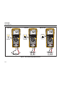
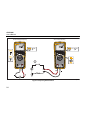
AC and DC Voltage Measurements .......................................................................... 13
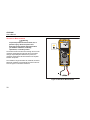
Volts/Hertz Ratio ....................................................................................................... 15
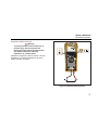
Resistance Measurements ....................................................................................... 16
Capacitance Measurements ..................................................................................... 17
Continuity Test .......................................................................................................... 18
AC or DC Current Measurements ............................................................................. 19
Diode Test ................................................................................................................ 21
Frequency Measurement .......................................................................................... 23
Remote Operation ......................................................................................................... 25
Radio Frequency Data .............................................................................................. 25
Discovery of Modules ................................................................................................ 26
How to Unbind a Module from the Product ............................................................... 29
How to Set the Product to Module Mode .................................................................. 29
Maintenance ............................................................................................................. 30
General Maintenance ................................................................................................ 30
Fuse Test ....................................................................................................................... 31
Battery and Fuse Replacement ..................................................................................... 32
Service and Parts .......................................................................................................... 34
Specifications ................................................................................................................ 36
Detailed Specifications .............................................................................................. 38
AC Voltage ................................................................................................................ 38
DC Voltage, Continuity, Resistance, Diode Test, and Capacitance .......................... 39
AC and DC Current ................................................................................................... 40
Frequency ................................................................................................................. 40
Frequency Counter Sensitivity .................................................................................. 41
Input Characteristics ................................................................................................. 42
MIN MAX Recording ................................................................................................. 42

iii
List of Tables
Table Title Page
1. Symbols ................................................................................................................................. 4
2. Power-Up Options ................................................................................................................. 8
3. Inputs .................................................................................................................................... 9
4. Rotary Switch Positions ......................................................................................................... 10
5. Pushbuttons .......................................................................................................................... 11
6. Replaceable Parts ................................................................................................................. 34
7. Accessories ........................................................................................................................... 36

CNX 3000
Users Manual
iv

v
List of Figures
Figure Title Page
1. AC and DC Voltage Measurements ...................................................................................... 14
2. Volt/Hertz Ratio ..................................................................................................................... 15
3. Resistance Measurements .................................................................................................... 16
4. Capacitance Measurements .................................................................................................. 17
5. Continuity Tests ..................................................................................................................... 18
6. AC and DC Current Measurements ....................................................................................... 20
7. Diode Test ............................................................................................................................. 22
8. Frequency Measurement....................................................................................................... 24
9. Module Binding Procedure .................................................................................................... 28
10. Fuse Test .............................................................................................................................. 31
11. Battery and Fuse Replacement ............................................................................................. 33
12. Replacement Parts ................................................................................................................ 35

CNX 3000
Users Manual
vi

1
Introduction
Warning
To prevent possible electrical shock, fire, or
personal injury, read all safety information
before you use the Product.
The CNX 3000 Wireless Multimeter (the Product) is a
True-rms Digital Multimeter.
How to Contact Fluke
To contact Fluke, call one of the following telephone
numbers:
• Technical Support USA: 1-800-44-FLUKE (1-800-
443-5853)
• Calibration/Repair USA: 1-888-99-FLUKE (1-888-
993-5853)
• Canada: 1-800-36-FLUKE (1-800-363-5853)
• Europe: +31 402-675-200
• Japan: +81-3-6714-3114
• Singapore: +65-6799-5566
• Anywhere in the world: +1-425-446-5500
Or, visit Fluke's website at www.fluke.com.
To register your product, visit http://register.fluke.com.
To view, print, or download the latest manual supplement,
visit http://us.fluke.com/usen/support/manuals.
Safety Information
The Product complies with:
• ANSI/ISA-82.02.01
• CAN/CSA-C22.2 No. 61010-1-12: 3rd Edition
• UL 61010-1: 3rd Edition
• IEC/EN 61010-1:2010
• FCC Part 15 Subpart C Section 15.207, 15.209,
15.249 FCCID: T68-FWCS
• IC:6627A-FWCS
• Measurement Category III, 1000V, Pollution
Degree 2
• Measurement Category IV, 600V, Pollution Degree 2

CNX 3000
Users Manual
2
A Warning identifies conditions and procedures that are
dangerous to the user. A Caution identifies conditions
and procedures that can cause damage to the Product or
the equipment under test.
A list of symbols used on the Product and in this manual
is in Table 1.
Warning
To prevent possible electrical shock, fire, or
personal injury:
• Carefully read all instructions.
• Use the Product only as specified, or the
protection supplied by the Product can
be compromised.
• Limit operation to the specified
measurement category, voltage, or
amperage ratings.
• Do not use the Product around explosive
gas, vapor, or in damp or wet
environments.
• Do not touch voltages > 30 V ac rms,
42 V ac peak, or 60 V dc.
• Do not exceed the Measurement
Category (CAT) rating of the lowest rated
individual component of a Product,
probe, or accessory.
• Measure a known voltage first to make
sure that the Product operates correctly.
• Do not use, and disable the Product if it
is damaged.
• Do not work alone.
• Comply with local and national safety
codes. Use personal protective
equipment (approved rubber gloves, face
protection, and flame-resistant clothes)
to prevent shock and arc blast injury
where hazardous live conductors are
exposed.
• Replace the batteries when the low
battery indicator shows to prevent
incorrect measurements.
• The battery door must be closed and
locked before you operate the Product.

Wireless Multimeter
Safety Information
3
• Do not use the Product if it operates
incorrectly.
• Examine the case before you use the
Product. Look for cracks or missing
plastic. Carefully look at the insulation
around the terminals.
• Use only correct measurement category
(CAT), voltage, and amperage rated
probes, test leads, and adapters for the
measurement.
• Do not use test leads if they are
damaged. Examine the test leads for
damaged insulation, exposed metal, or if
the wear indicator shows. Check test
lead continuity.
• Keep fingers behind the finger guards on
the probes.
• Do not touch the probes to a voltage
source when the test leads are
connected to the current terminals.
• Connect the common test lead before
the live test lead and remove the live test
lead before the common test lead.
• Remove all probes, test leads, and
accessories that are not necessary for
the measurement.

CNX 3000
Users Manual
4
Table 1. Symbols
Symbol Description Symbol Description
Risk of Danger. Important information. See
Manual. Hazardous voltage.
Conforms to European Union directives. Conforms to relevant Australian EMC requirements.
Conforms to relevant North American Safety
Standards. Fuse
Battery Double insulation.
CAT III
Measurement Category III is applicable to test
and measuring circuits connected to the
distribution part of the building’s low-voltage
MAINS installation.
CAT IV
Measurement Category IV is applicable to test and
measuring circuits connected at the source of the
building’s low-voltage MAINS installation.
CAT II Measurement Category II is applicable to test and measuring circuits connected directly to utilization points
(socket outlets and similar points) of the low-voltage MAINS installation.

Wireless Multimeter
Hazardous Voltage
5
Table 1. Symbols (cont.)
Symbol Description
This product complies with the WEEE Directive (2002/96/EC) marking requirements. The affixed label indicates
that you must not discard this electrical/electronic product in domestic household waste. Product Category: With
reference to the equipment types in the WEEE Directive Annex I, this product is classed as category 9
"Monitoring and Control Instrumentation" product. Do not dispose of this product as unsorted municipal waste. Go
to Fluke’s website for recycling information.
Hazardous Voltage
The display shows and the hazardous voltage indicator
illuminates red when a hazardous voltage (≥30 V) is
present on the input of the Product
Test Lead Alert
The display shows LEAD for a second when you turn the
function switch to or from the mA position to remind you
to make sure the test leads are in the correct terminals.
Battery Saver
The Product goes into “Sleep mode” and turns off the
display if there is no function change or button pushed for
20 minutes. To turn off the sleep mode, push while
you turn on the Product. The sleep mode is always turned
off for a MIN MAX AVG record session and when remote
modules are shown in the display.

CNX 3000
Users Manual
6
MIN MAX AVG Record Mode
The MIN MAX AVG record mode records the minimum
and maximum input values, and calculates a running
average of all measurements. The Product beeps when a
new high or low is sensed.
Note
For dc functions, accuracy is the specified
accuracy of the measurement function,
±
12 counts for changes longer than 250 ms in
duration.
For ac functions, accuracy is the specified
accuracy of the measurement function
±
40 counts for changes longer than 900 ms in
duration.
To start a MIN MAX AVG record session:
1. Make sure the Product is set to the correct
measurement function and on the correct range.
Autorange is disabled while in a MIN MAX AVG
record session.
2. Push . and Max show at the top of
the display. The measurement in the display is the
maximum value measured. It will change only when
a new maximum value is sensed.
3. To pause MIN MAX AVG record, push .
shows in the display while record is paused.
Recorded values are not deleted. To continue record
session, push .
4. To exit and erase the MIN, MAX, and AVG values,
push for 1 second or turn the rotary switch.
5. To see the other recorded values (minimum and
average), push . Each push of the button
shows a different recorded value. The value shown in
the display is identified with Max, Min, or Avg to the
right of the MIN MAX icon.
Note
Battery save or sleep mode is turned off in MIN
MAX AVG record mode.

Wireless Multimeter
Display Hold
7
Display Hold
Warning
To prevent possible electrical shock, fire, or
personal injury, do not use the HOLD
function to measure unknown potentials.
When HOLD is turned on, the display does
not change when a different potential is
measured.
In the display hold mode, the Product holds the DMM
measurement in the display. All wireless module
measurements continue to update. To hold a
measurement in the display, push . The display
shows when display hold is turned on.
Push again to stop hold mode and show
measurements in the display.
Yellow Button
Push the YELLOW button ( ) to set the Product to a
different measurement function. The different functions
are shown in yellow around the rotary switch. Frequency,
mV ac, capacitance, diode test, and mA dc are functions
of the Product set with the yellow button.
Display Backlight
Push to turn on and turn off the backlight. The
backlight automatically turns off after 2 minutes.
Manual and Auto Range
The Product can be set to manual or auto range. In
autorange, the Product sets the range so the input is
shown with the best resolution. Manual range lets you set
the range.
When you turn on the Product, it is set to autorange and
Auto shows in the display. To set the Product to manual
range, push .
Note
You cannot change range when the Product is in
the MIN MAX AVG record mode or in display
hold mode. If you push in one of these
modes, the Product will beep twice to alert you
to an invalid operation.

CNX 3000
Users Manual
8
Power-Up Options
To set a power-up option, hold down the button shown in
Table 2 while you turn on the Product.
Table 2. Power-Up Options
Button Power-Up Option
Turns off the beeper.
(YELLOW)
Turns off battery save (“Sleep mode”).
POFF shows in the display for a second.
Turns off 2 minute backlight timeout. LOFF
shows in the display for a second.
Sets the Product to the module mode. See
the “How to Set the Product to Module
Mode.”

Wireless Multimeter
Features
9
Features
Tables 3 through 5 are lists of Product features with descriptions.
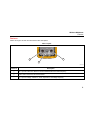
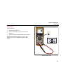
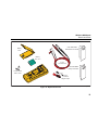
Table 3. Inputs
31
2
gxr001.eps
Terminal Description
mA - Input for 3.00 mA to 400.0 mA current measurements and current frequency.
COM - Return terminal for all measurements.
- Input for voltage, resistance, diode, capacitance, and voltage frequency.

CNX 3000
Users Manual
10
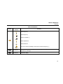
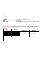
Table 4. Rotary Switch Positions
Switch
Position Function
DC voltage from 1 mV to 1000 V.
Push to measure frequency from 2 Hz to 99.99 kHz
AC voltage measurement from 60.0 mV to 1000 V.
Push to measure frequency from 2 Hz to 99.99 kHz.
Push again to measure Volts/Hertz.
DC voltage measurements from 1 mV to 600 mV.
Push to measure ac voltage from 6 mV to 600 mV. [1]
Resistance measurements from 0.1 Ω to 50 MΩ.
Push to measure capacitance from 1 nF to 9999 μF.
Continuity. Beeper turns on at <25 Ω and turns off at >250 Ω.
Push for diode test. Shows OL above 2.0 V.
AC current measurements from 3.00 mA to 400 mA.
Push to measure dc current from 3.00 mA to 400 mA. [1]
Push again to measure frequency from 2 Hz to 9.99 kHz.
[1] This function will stay in ac or dc when the function switch is moved to another position and back to this function. Even when turned to off and back to
this function.

Wireless Multimeter
Features
11
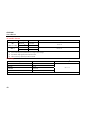
Table 5. Pushbuttons
Button Switch
Position Function
Selects frequency.
Selects frequency.
Selects ac millivolts. [1]
Selects capacitance.
Selects diode test.
Push once to select dc milliamps. Push twice to select ac frequency. [1]
All positions Sets the Product to manual range and scrolls through each range. Push for 1 second to set
the Product to autorange.
All positions Freezes the display

CNX 3000
Users Manual
12
Table 5. Pushbuttons (cont.)
Button Switch
Position Function
Not related to
switch position
Push once to turn on the backlight and push again to turn off the backlight. The backlight
turns off automatically after 2 minutes.
All positions Starts the MIN MAX record function. Steps the display through MAX, MIN, AVG (average),
and input signal measurement. Push for 1 second to stop MIN MAX record.
Not related to
switch position
Selects/deselects the highlighted wireless module in the display. Hold for 1 second to bind
all selected modules to the Product and stop the discovery procedure. [2]
Not related to
switch position Moves the highlight in the display to the next wireless module shown in the display. [2]
Not related to
switch position
Turns on the radio and starts the module discovery procedure. shows in the display
when the radio is on. Turns off the radio when the radio is on. [2]
[1] This function will stay in ac or dc when the function switch is moved to another position and back to this function. Even when turned to off and back to
this function.
[2] This button is used when the Product connects with a wireless module. See the “Discovery of Modules” section to learn more.
Page is loading ...
Page is loading ...
Page is loading ...
Page is loading ...
Page is loading ...
Page is loading ...
Page is loading ...
Page is loading ...
Page is loading ...
Page is loading ...
Page is loading ...
Page is loading ...
Page is loading ...
Page is loading ...
Page is loading ...
Page is loading ...
Page is loading ...
Page is loading ...
Page is loading ...
Page is loading ...
Page is loading ...
Page is loading ...
Page is loading ...
Page is loading ...
Page is loading ...
Page is loading ...
Page is loading ...
Page is loading ...
Page is loading ...
Page is loading ...
-
 1
1
-
 2
2
-
 3
3
-
 4
4
-
 5
5
-
 6
6
-
 7
7
-
 8
8
-
 9
9
-
 10
10
-
 11
11
-
 12
12
-
 13
13
-
 14
14
-
 15
15
-
 16
16
-
 17
17
-
 18
18
-
 19
19
-
 20
20
-
 21
21
-
 22
22
-
 23
23
-
 24
24
-
 25
25
-
 26
26
-
 27
27
-
 28
28
-
 29
29
-
 30
30
-
 31
31
-
 32
32
-
 33
33
-
 34
34
-
 35
35
-
 36
36
-
 37
37
-
 38
38
-
 39
39
-
 40
40
-
 41
41
-
 42
42
-
 43
43
-
 44
44
-
 45
45
-
 46
46
-
 47
47
-
 48
48
-
 49
49
-
 50
50


Ask a question and I''ll find the answer in the document
Finding information in a document is now easier with AI
Related papers
-
Fluke v3000 FC Wireless AC Voltage Kit User manual
-
Fluke FLUKE-IR3000FC User guide
-
Fluke 233 User manual
-
Fluke 28 II Ex Intrinsically Safe True RMS Digital Multimeter User manual
-
-
Fluke 1577 Insulation Multimeter User manual
-
-
-
-
Fluke 3000 FC industrisystem User manual