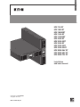
Eaton 9PX 1000 GRT Installation and User Manual
- Type
- Installation and User Manual

ENGLISH
9PX 700 RT
9PX 1000 RT
9PX 1000GRT
9PX 1500 RT
9PX 1500GRT
9PX 2000 RT
9PX 2200 GRT
9PX 3000 RT
9PX 3000 GRT
9PX 3000 GLRT
9PX EBM 36V RT
9PX EBM 48V RT
9PX EBM 72V RT
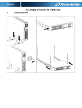
Installation
and user manual
Copyright © 2016 EATON
All rights reserved.
9PX 1-3 KVA US_EN

Page 2
9PX 1-3 KVA US_EN
SAVE THESE INSTRUCTIONS. This manual contains important instructions
that should be followed during installation and maintenance of the UPS and batteries.
The 9PX models that are covered in this manual are intended for installation
in an environment within 0 to 40°C, free of conductive contaminant.
This equipment has been tested and found to comply with the limits for a Class A digital device,
pursuant to Part 15 of the FCC Rules. These limits are designed to provide reasonable protection against
harmful interference when the equipment is operated in a commercial environment. This equipment
generates, uses, and can radiate radio frequency energy and, if not installed and used in accordance
with the instruction manual, may cause harmful interference to radio communications. Operation of
this equipment in a residential area is likely to cause harmful interference in which case the user will
be required to correct the interference at his own expense.
Special symbols
The following are examples of symbols used on the UPS or accessories to alert you to important
information:
RISK OF ELECTRIC SHOCK - Observe the warning associated with the risk of electric shock symbol.
Important instructions that must always be followed.
Do not discard the UPS or the UPS batteries in the trash.
This product contains sealed lead acid batteries and must be disposed as it's explain in this manual.
For more information, contact your local recycling/reuse or hazardous waste center.
This symbol indicates that you should not discard waste electrical or electronic equipment (WEEE)
in the trash. For proper disposal, contact your local recycling/reuse or hazardous waste center.
Information, advice, help.
Refer to the user manual of UPS accessories.
SAFETY INSTRUCTIONS

Page 3
9PX 1-3 KVA US_EN
ENGLISH
SAFETY INSTRUCTIONS
Safety of persons
• The system has its own power source (the battery). Consequently, the power outlets may be ener-
gized even if the systems is disconnected from the AC power source. Dangerous voltage levels are
presentwithinthesystem.Itshouldbeopenedexclusivelybyqualiedservicepersonnel.
• The system must be properly grounded at all times.
• The battery supplied with the system contains small amounts of toxic materials.
To avoid accidents, the directives listed below must be observed:
- Servicing of batteries should be performed or supervised by personnel knowledgeable about bat-
teries and the required precautions.
- When replacing batteries, replace with the same type and number of batteries or battery packs.
-Donotdisposeofbatteriesinare.Thebatteriesmayexplode.
- Batteries constitute a danger (electrical shock, burns). The short-circuit current may be very high.
• Precautions must be taken for all handling:
- Wear rubber gloves and boots.
- Do not lay tools or metal parts on top of batteries.
- Disconnect charging source prior to connecting or disconnecting battery terminals.
- Determine if battery is inadvertently grounded. If inadvertently grounded, remove source from
ground. Contact with any part of a grounded battery can result in electrical shock. The likelihood
of such shock can be reduced if such grounds are removed during installation and maintenance
(applicable to equipment and remote battery supplies not having a grounded supply circuit).
Product safety
• To connect the UPS, instructions and operation described in the manual must be followed in
the indicated order.
• CAUTION-Toreducetheriskofre,theunitconnectsonlytoacircuitprovided
with 20 or 30 amperes maximum branch circuit overcurrent protection in accordance with the
National Electric Code, ANSI/NFPA 70 (US installations only).
• Check that the indications on the rating plate correspond to your AC powered system and
to the actual electrical consumption of all the equipment to be connected to the system.
• For PLUGGABLE EQUIPMENT, the socket-outlet shall be installed near the equipment and shall
be easily accessible
• Never install the system near liquids or in an excessively damp environment.
• Never let a foreign body penetrate inside the system.
• Never block the ventilation grates of the system.
• Never expose the system to direct sunlight or source of heat.
• If the system must be stored prior to installation, storage must be in a dry place.
• The admissible storage temperature range is -25ºC to +55ºC without batteries, 0°C to 40°C with
batteries.
• The system is not for use in a computer room AS DEFINED IN the standard for the Protection
of Information Technology Equipment, ANSI/NFPA 75 (US installations only).
Contact Eaton resellers to order a special battery kit, if needed to meet the ANSI/NFPA 75
requirement.

Page 4
9PX 1-3 KVA US_EN
SAFETY INSTRUCTIONS
Special precautions
• The unit is heavy: wear safety shoes and use vacuum lifter preferentially for handling operations.
• All handling operations will require at least two people (unpacking, lifting, installation in rack
system).
• Before and after the installation, if the UPS remains de-energized for a long period, the UPS
must be energized for a period of 24 hours, at least once every 6 months (for a normal storage
temperature less than 25°C). This charges the battery, thus avoiding possible irreversible damage.
• During the replacement of the Battery Module, it is imperative to use the same type and number of
element as the original Battery Module provided with the UPS to maintain an identical level of
performance and safety. If there are any questions, don’t hesitate to contact your EATON
representative.
• All repairs and service should be performed by AUTHORIZED SERVICE PERSONNEL ONLY.
There are NO USER SERVICEABLE PARTS inside the UPS.
• For potential safety issue on defective UPS : DISCONNECT INTERNAL BATTERY for storage and
transportation.

Page 5
9PX 1-3 KVA US_EN
ENGLISH
Contents
1. Introduction .........................................................................................
1.1 Environmental protection ............................................................................................... 6
2. Presentation ........................................................................................
2.1 Standard installations ..................................................................................................... 8
2.2 Rear panels ....................................................................................................................9
2.3 Accessories .................................................................................................................10
2.4 Control panel ................................................................................................................ 11
2.5 LCD description ...........................................................................................................12
2.6 Display functions .........................................................................................................13
2.7 User settings ...............................................................................................................13
3. Installation ..........................................................................................
3.1 Inspecting the equipment ...........................................................................................17
3.2 Checking the accessory kit .......................................................................................... 17
3.3 Connecting the internal battery ...................................................................................21
3.4 Connecting the EBM(s) ...............................................................................................22
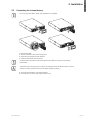
3.5 Connecting other accessories ....................................................................................22
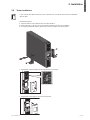
3.6 Tower installation .........................................................................................................23
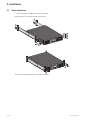
3.7 Rack installation ...........................................................................................................24
3.8 UPS connection without HotSwap MBP module ........................................................25
3.9 Connection with a HotSwap MBP module (optional accessory) ........................................ 26
4. Communication ..................................................................................
4.1 Communication ports ..................................................................................................28
4.2 UPS remote control functions .....................................................................................29
4.3 Eaton Intelligent Power Software suite .......................................................................31
5. Operation.............................................................................................
5.1 Start-up and Normal operation ..................................................................................... 32
5.2 Starting the UPS on Battery ......................................................................................... 32
5.3 UPS Shutdown ............................................................................................................32
5.4 Operating modes .........................................................................................................32
5.5 Return of AC Input Power ............................................................................................33
5.6 Setting High Efciency mode ......................................................................................33
5.7 Conguring Bypass settings ........................................................................................33
5.8 Conguring battery settings ........................................................................................34
5.9 Retrieving the Event log ...............................................................................................34
5.10 Retrieving the Fault log ................................................................................................34
6. UPS maintenance ...............................................................................
6.1 Equipment care ............................................................................................................35
6.2 Storing the equipment .................................................................................................35
6.3 When to replace batteries ...........................................................................................35
6.4 Replacing batteries ......................................................................................................36
6.5 Replacing the UPS equipped with a HotSwap MBP .................................................... 38
6.6 Recycling the used equipment ....................................................................................38
7. Troubleshooting ...................................................................................
7.1 Typical alarms and faults ..............................................................................................39
7.2 Silencing the alarm ......................................................................................................40
7.3 Service and support .....................................................................................................40
7.4 CE compliance contact ................................................................................................40
8. Specications ......................................................................................
8.1 Model specications ..................................................................................................41
9. Glossary ........................................................................................... 45

Page 6
9PX 1-3 KVA US_EN
1. Introduction
Thank you for selecting an EATON product to protect your electrical equipment.
The 9PX range has been designed with the utmost care.
We recommend that you take the time to read this manual to take full advantage of the many features
of your UPS (Uninterruptible Power System).
Before installing your 9PX, please read the booklet presenting the safety instructions.
Then follow the indications in this manual.
To discover the entire range of EATON products and the options available for the 9PX range, we invite you
to visit our web site at www.eaton.com/powerquality or contact your EATON representative.
1.1 Environmental protection
EATON has implemented an environmental-protection policy.
Products are developed according to an eco-design approach.
Substances
This product does not contain CFCs, HCFCs or asbestos.
Packing
To improve waste treatment and facilitate recycling, separate the various packing components.
• The cardboard we use comprises over 50% of recycled cardboard.
• Sacks and bags are made of polyethylene.
• Packingmaterialsarerecyclableandbeartheappropriateidenticationsymbol
01
PET
Materials Abbreviations
Number in
01
PET
the symbols
Polyethylene terephthalat PET 01
High-density polyethylene HDPE 02
Polyvinyl chloride PVC 03
Low-density polyethylene LDPE 04
Polypropylene PP 05
Polystyrene PS 06
Follow all local regulations for the disposal of packing materials.
End of life
EATON will process products at the end of their service life in compliance with local regulations.
EATON works with companies in charge of collecting and eliminating our products at the end of
their service life.
Product
The product is made up of recyclable materials.
Dismantling and destruction must take place in compliance with all local regulations concerning waste.
At the end of its service life, the product must be transported to a processing center for electrical and
electronic waste.
Battery
The product contains lead-acid batteries that must be processed according to applicable local regulations
concerning batteries.
The battery may be removed to comply with regulations and in view of correct disposal.

Page 7
9PX 1-3 KVA US_EN
ENGLISH
1. Introduction
The Eaton
®
9PX uninterruptible power system (UPS) protects your sensitive electronic equipment from the
most common power problems, including power failures, power sags, power surges, brownouts, line noise,
high voltage spikes, frequency variations, switching transients, and harmonic distortion.
Power outages can occur when you least expect it and power quality can be erratic. These power problems
have the potential to corrupt critical data, destroy unsaved work sessions, and damage hardware - causing
hours of lost productivity and expensive repairs.
With the Eaton 9PX, you can safely eliminate the effects of power disturbances and guard the integrity
ofyourequipment.Providingoutstandingperformanceandreliability,theEaton9PX’suniquebenets
include:
• True online double-conversion technology with high power density, utility frequency independence, and
generator compatibility.
• ABM
®
technology that uses advanced battery management to increase battery service life, optimize
recharge time, and provide a warning before the end of useful battery life.
• SelectableHighEfciencymodeofoperation.
• Standard communication options: one RS-232 communication port, one USB communication port, and
relay output contacts.
• Optional connectivity cards with enhanced communication capabilities.
• Extended runtime with up to four Extended Battery Modules (EBMs) per UPS.
• Remote On/Off control through Remote On/Off (ROO) and Remote Power Off (RPO) ports.
• Backed by worldwide agency approvals.

Page 8
9PX 1-3 KVA US_EN
2. Presentation
2.1 Standard installations
Tower installation
D
W
H
Rack installation
D
H
W
Description Weights
(lb/kg)
Dimensions (inch/mm)
D x W x H
9PX700RT 36.4 / 16.5 17.7 x 17.3 x 3.4 / 450 x 440 x 86.5
9PX1000RT 36.4 / 16.5 17.7 x 17.3 x 3.4 / 450 x 440 x 86.5
9PX1000GRT 38.6 / 17.5 17.7 x 17.3 x 3.4 / 450 x 440 x 86.5
9PX1500RT 42.5 / 19.3 17.7 x 17.3 x 3.4 / 450 x 440 x 86.5
9PX1500GRT 41.4 / 18.8 17.7 x 17.3 x 3.4 / 450 x 440 x 86.5
9PX2000RT 61.6 / 27.9 23.8 x 17.3 x 3.4 / 605 x 440 x 86.5
9PX2200GRT 59.7 /
27.1 23.8 x 17.3 x 3.4 / 605 x 440 x 86.5
9PX3000RT 63
/ 28.6 23.8 x 17.3 x 3.4 / 605 x 440 x 86.5
9PX3000GRT 61.2
/ 27.8 23.8 x 17.3 x 3.4 / 605 x 440 x 86.5
9PX3000GLRT 61
/ 27.7 23.8 x 17.3 x 3.4 / 605 x 440 x 86.5
9PXEBM36RT 48.1
/ 21.8 17.7 x 17.3 x 3.4 / 450 x 440 x 86.5
9PXEBM48RT 59.5
/ 27 17.7 x 17.3 x 3.4 / 450 x 440 x 86.5
9PXEBM72RT 86.4
/ 39.2 23.8 x 17.3 x 3.4 / 605 x 440 x 86.5

Page 9
9PX 1-3 KVA US_EN
ENGLISH
2. Presentation
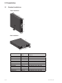
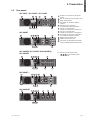
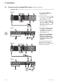
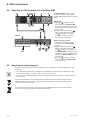
2.2 Rear panels
9PX 700RT / 9PX 1000RT / 9PX 1500RT
1 2 3 4 5 6
9 811 10 7
9PX 2000RT
1 82 43
5 6
9 1011
7
9PX 1000GRT, 9PX 1500GRT, 9PX 2200GRT &
9PX 3000GRT
1 82 43
5
9 1011
6 7
9PX 3000RT
(*)
1 82 43
5 6
9 1011
7
9PX 3000GLRT
1 82 43 5 6 7
9 1011
1
Socket for connection to AC power
source
2
Slot for optional communication card
3
Relay output contact
4
Connector for additional battery
module
5
Primary group: outlets for
connection of critical equipment
6
Group 1: programmable
outlets for connection of equipment
7
Group 2: programmable
outlets for connection of equipment
8
Connector for automatic recognition
of an additional battery module
9
RS232 communication port
10
USB communication port
11
Connector for ROO (Remote On/Off)
control and RPO (Remote Power Off)
(*) Primary and Grouped outlets
(
5
,
6
,
7
) are protected by 20A
circuit breakers.

Page 10
9PX 1-3 KVA US_EN
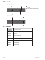
2. Presentation
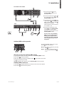
9PX EBM 36V/48V
13 13
1212
12
Connectors for battery modules
(to the UPS or to the other battery
modules)
13
Connectors for automatic recognition
of battery modules
9PX EBM 72V
13 13
1212
2.3 Accessories
Part number Description
9PXEBM36RT2U
9PXEBM48RT2U
9PXEBM72RT2U
Extended battery module
9RK Rack kit 9PX
Network-MS Network card
Modbus-MS Modbus and network card
Relay-MS Relay card
BINTSYS Battery Integration System
EBMCBL36 2m cable 36V EBM
EBMCBL48 2m cable 48V EBM
EBMCBL72 2m cable 72V EBM

Page 11
9PX 1-3 KVA US_EN
ENGLISH
2. Presentation
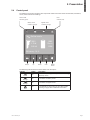
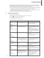
2.4 Control panel
TheUPShasave-buttongraphicalLCD.ItprovidesusefulinformationabouttheUPSitself,loadstatus,
events, measurements and settings.
Online mode
indicator (green)
Fault
indicator (red)
Online mode
100%
19min
1EBM
100%
2.7kW
3.0kVA
Efficiency: 94 %
Escape Up Down Enter On/Off
button
Battery mode
indicator (orange)
Bypass mode
indicator (orange)
The following table shows the indicator status and description:
Indicator Status Description
Green
On
The UPS is operating normally on Online or on High
Efficiency mode.
Orange
On The UPS is on Battery mode.
Orange
On The UPS is on Bypass mode.
Red
On
The UPS has an active alarm or fault. See trouble-
shooting on page 39 for additional information.

Page 12
9PX 1-3 KVA US_EN
2. Presentation
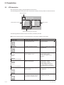
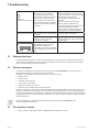
2.5 LCD description
After 5 minutes of inactivity, the LCD displays the screen saver.
The LCD backlight automatically dims after 10 minutes of inactivity. Press any button to restore the screen.
Operation status
Load/equipment status
Online mode
100%
19min
1EBM
100%
2.7kW
3.0kVA
Efficiency: 94%
Battery status
Efficiency and load group information
The following table describes the status information provided by the UPS
Note: If other indicator appears, see troubleshooting on page 39 for additional information.
Operation status Cause Description
Standby mode
The UPS is Off, waiting form start-
up command from user.
Equipment is not powered until
button is pressed.
Online mode
The UPS is operating normally. The UPS is powering and protecting
the equipment.
Battery mode
1 beep every 10 seconds
A utility failure has occured and the
UPS is on Battery mode.
The UPS is powering the equipment
with the battery power.
Prepare your equipment for
shutdown.
End of backup time
1 beep every 3 seconds
The UPS is on Battery mode and the
battery is running low.
Low Battery Warning settings:
[Capacity] [0%] ... [100%]
[Runtime] [0mn] ... [60mn]
The alarm triggers when the set
percentage of battery capacity or
remaining back-up time is reached.
High Efficiency mode The UPS is operating on High
Efficiency mode.
The UPS is powering and protecting
the equipment
Bypass mode
An overload or a fault has occurred,
or a command has been received,
and the UPS is in Bypass mode.
Equipment is powered but not
protected by the UPS.

Page 13
9PX 1-3 KVA US_EN
ENGLISH
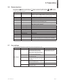
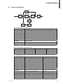
2.6 Display functions
Press the Enter ( ) button to activate the menu options. Use the two middle buttons ( and ) to scroll
through the menu structure. Press the Enter ( ) button to select an option. Press the button to cancel
or return to the previous menu.
Main menu Submenu Display information or Menu function
Measurements [Load] W VA A pf / [Input/Output] V Hz / [Efficiency] % /
[Battery] % min V n° EBM / [Battery remaining life] months /
[Average power usage] Wh / [Cumulated power] Wh
Control Go to Bypass Transfers the UPS on Bypass mode
Load segments On/Off Commands the load segments
Start battery test Starts a manual battery test
Connectivity test Tests dry contact relay outputs and relay card contacts.
Simulates line failure and battery low
Function reset Clears active fault, power usage, battery remaining life, reset
NMC, Restore factory settings.
Settings Local settings Sets product general parameters
In/Out settings Sets Input and Output parameters
On/Off settings Sets On/Off conditions
Battery settings Sets battery configuration
Com settings Sets communication parameters
Event log Event filter Selects faults, alarms and/or events to display
Event list Displays the events stored
Reset event list Clears events
Fault log Fault list Displays the faults stored
Reset fault list Clears faults
Identification [Product type/model] / [Part/Serial number] / [UPS/NMC firm-
ware] / [Com card IPv4], [Com card IPv6], [Com card MAC]
Registration Links to Eaton registration website
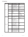
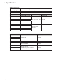
2.7 User settings
The following table displays the options that can be changed by the user.
Submenu Available settings Default settings
Local settings
Language [English] [Français] [Deutsch] [Español]
[Русский] [Português] [Italiano]
[Simplified Chinese] [Japanese]
Menus, status, notices and alarms,
UPS fault, Event Log data and settings
are in all supported languages.
[English]
User selectable when UPS is
powered for the first time.
Date/ time Format:
[International] [US]
[US]
LCD Modify LCD screen brightness and
contrast to be adapted to room light
conditions.
Audible alarm
Mode: [Enabled] [Disabled on battery]
[Always disabled] Enable or disable the
buzzer if an alarm occurs.
[Enabled]
Level: [High] [Low]
[High]
Protected access [Enabled] [Disabled]
Password is: 0577
[Disabled]
2. Presentation

Page 14
9PX 1-3 KVA US_EN
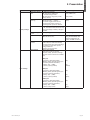
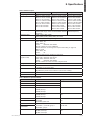
2. Presentation
Submenu Available settings Default settings
In/Out settings
Output voltage [100V] [110V] [120V] [125V]
[200V] [208V] [220V] [230V] [240V]
[120V]
[208V]
Output frequency Mode: [Normal] [Converter] [Marine]
Frequency can be changed in
Frequency [Converter] mode
In [Marine] mode output frequency
follows input frequency
[Normal]
Output mode Mode: [Industrial] [IT] [Custom]
Overload: [Inv>Stop] [Inv>BP]
[Inv>BP>Inv]
Short-circuit: [Inv>Stop] [Inv>BP]
[Inv>BP>Inv]
[IT]
[Inv>BP>Inv]
[Inv>Stop]
Input volt hysteresis Sets input voltage hysteresis
from [1] to |10V]
[10V]
High Efficiency
mode
[Enabled] [Disabled]
Power the output from Bypass for high
efficiency
[Disabled]
Bypass settings
[Volt low]
[Volt high]
[Qualify]
[Hz synch]
[Unsynch]
[80V] LV; [160V] HV;
[144V] LV; [276V] HV;
[In spec];
[5%];
[Half cycle]
Load segments
[Auto start delay]
[Auto shutdown delay]
UPS: [0s]; Group1: [3s];
Group2: [6s]
UPS: [Disabled];
Group1: [Disabled];
Group2: [Disabled]
Overload
prealarm
[10%] … [102%]
Load % when overload alarm occurs
[102%]
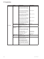
On/Off settings
Start/Restart [Cold start] [Auto restart] [Auto start]
[Start on bypass]
[Cold start] [Auto restart] are
Enabled
[Auto start] [Start on bypass]
are Disabled
Forced reboot [Enabled] [Disabled]
[Timer] [10s] … [180s]
When mains recover during a
shutdown sequence:
If set to Enabled, shutdown sequence
will complete and wait 10 seconds
prior to restart,
If set to Disabled, shutdown sequence
will not complete, UPS stays on.
[Enabled]
[10s]
Energy saving [Enabled] [Disabled]
[Timer] [1min] … [15min]
[Level] [100W] … [1000W]
If Enabled, UPS will shut-down after
defined duration. of back-up time, if
load is less than set value.
[Disabled]
[5min]
[100W]
Sleep mode [Enabled] [Disabled]
[Timer] [10min] … [120min]
If Disabled, LCD and communication
will turn OFF immediately after UPS is
OFF.
If Enabled, LCD and communication
stays ON 1h30 min after UPS is OFF.
[Enabled]
[90min]
Site wiring fault [Enabled] [Disabled]
Prevents from starting the UPS in case
of phase vs neutral wires swapping.
[Disabled]
Power Off alert [Enabled] [Disabled]
If Enabled, activates a confirmation
screen that requires user confirmation
after pressing the power button,
before the UPS shutdown occurs.
[Enabled]

Page 15
9PX 1-3 KVA US_EN
ENGLISH
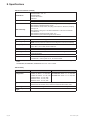
Submenu Available settings Default settings
Battery settings
Automatic battery
test
In ABM cycling mode :
[No test] [Every ABM cycle]
In constant charge mode:
[No test] [Every day] [Every week]
[Every month]
[Every ABM cycle]
[Every week]
Low battery
warning
[Capacity] [0%] … [100%]
[Runtime] [0min] … [60min]
The alarm triggers when the set
percentage of battery capacity or
remaining back-up time is reached.
[0%]
[3min]
Restart bat. level [0%] ... [100%]
If set, automatic restart will occur only
when percentage of battery charge is
reached.
[0%]
Battery charge
mode
[ABM cycling] [Constant charge] [ABM cycling]
External battery [Auto detection] [Manual EBM set.]
[Manual battery set.]
[Auto detection]
Using standard EBM, UPS
detects automatically the
number of EBM connected
Deep Disch.
protect.
[Yes] [No]
If set to Yes, the UPS automatically
prevents battery from deep discharge
by adapting end of back-up time
voltage threshold.
Warranty void if set to No.
[Yes]
Com settings
Input signals [ROO] [RPO] [DB9-4]
Sets Input signals parameters
(function, delay, operation) through
external contact connectors or RS232
port.
ROO port:
- [Function]: [No] [ROO] [RPO]
[Building alarm] [Forced bypass] [On
generator] [Remote shutdown]
- [Delay]: [0s] … [999s]
- [Active]: [Open] [Closed]
RPO port:
- [Function]: [No] [ROO] [RPO]
[Building alarm] [Forced bypass] [On
generator] [Remote shutdown]
- [Delay]: [0s] … [999s]
- [Active]: [Open] [Closed]
DB9-4 port:
- [Function]: [No] [ROO] [RPO]
[Building alarm] [Forced bypass] [On
generator] [Remote shutdown]
- [Delay]: [0s] … [999s]
- [Active]: [High] [Low]:
[No]
[0s]
[Closed]
[No]
[0s]
[Open]
[No]
[0s]
[High]
2. Presentation

Page 16
9PX 1-3 KVA US_EN
2. Presentation
Submenu Available settings Default settings
Com settings
Output signals [Relay] [DB9-1] [DB9-7] [DB9-8]
Sets events or fault that will actuate
Output signal parameters through
external contact connector or RS232
port
[Relay]: [On bat] [Low bat] [Bat fault]
[Bypass] [UPS OK] [Load protected]
[Load powered] [General alarm] [Ext.
charger ON] [OVL pre-alarm]
[DB9-1]: [On bat] [Low bat] [Bat fault]
[Bypass] [UPS OK] [Load protected]
[Load powered] [General alarm] [Ext.
charger ON] [OVL pre-alarm]
[DB9-7]: [On bat] [Low bat] [Bat fault]
[Bypass] [UPS OK] [Load protected]
[Load powered] [General alarm] [Ext.
charger ON] [OVL pre-alarm]
[DB9-8]: [On bat] [Low bat] [Bat fault]
[Bypass] [UPS OK] [Load protected]
[Load powered] [General alarm] [Ext.
charger ON] [OVL pre-alarm]
[Relay] [Bypass]
[DB9-1] [Low bat]
[DB9-7] [UPS OK]
[DB9-8] [On bat]
Remote command [Enabled] [Disabled]
If Enabled, shutdown or restart
commands from software are
authorized.
[Enabled]
Shutdown
commands
[Send CMD] [Output OFF] [OFF delay]
[restart]
Sets events or fault that will actuate
Output signal parameters through
external contact connector or RS232
port
[Send CMD]: [Yes] [No]
[Output OFF]: [No] [UPS] [Group 1]
[Group 2] [Group 1 + Group 2]
[OFF delay]: [0s] …[999s]
[Restart]: [Yes] [No]
Send CMD: [No]
Output OFF: [No]
OFF delay: [0s]
Restart: [Yes]
On battery notice
delay
[0s] ... [99s]
Sets delay before noticing on battery
information to software.
[0s]
General alarm [On battery] [Battery fault]
[Overload pre-alarm] [Internal fault]
[Ambient temp.] [Fan lock]
[Bypass overload] [Current limit]
[Short circuit] [Inverter overload]
[Power overload] [Low battery]
[On bypass] [UPS OK] [Load protected]
[Load powered] [Ext. charger ON]
Defines which event or fault generate
a general alarm through Output signal
screen.
[Internal fault]

Page 17
9PX 1-3 KVA US_EN
ENGLISH
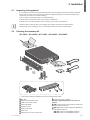
3.1 Inspecting the equipment
If any equipment has been damaged during shipment, keep the shipping cartons and packing materials
forthecarrierorplaceofpurchaseandleaclaimforshippingdamage.Ifyoudiscoverdamageafter
acceptance,leaclaimforconcealeddamage.
Toleaclaimforshippingdamageorconcealeddamage:
1. File with the carrier within 15 days of receipt of the equipment;
2. Send a copy of the damage claim within 15 days to your service representative.
Check the battery recharge date on the shipping carton label. If the date has passed and the
batteries were never recharged, do not use the UPS. Contact your service representative.
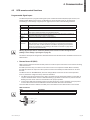
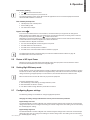
3.2 Checking the accessory kit
9PX 700RT / 9PX 1000RT / 9PX 1500RT / 9PX 2000RT / 9PX 3000RT
3. Installation
14
25
26
24
27
20
21 2322
17
18
14
9PX UPS
17
RS232 communication cable
18
USB communication cable
20
Manual CD-ROM
21
Software leaflet
22
Safety instructions
23
Quick start
24
Mounting kit for 19-inch enclosures
25
2 supports for tower position
Elements supplied depending on the version or
optional
26
NMC communication card (optional, standard on
Network Bundle models)
27
MBP-115 module for 9PX 700RT, 9PX 1000RT and
9PX 1500RT (optional)
MBP-120 module for 9PX 2000RT (optional)
MBP-130 module for 9PX 3000RT(optional)
• Verify that the following additional items are included with the UPS:

Page 18
9PX 1-3 KVA US_EN
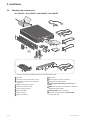
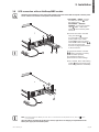
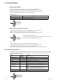
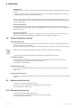
3.2 Checking the accessory kit
9PX 1000GRT / 9PX 1500GRT / 9PX 2200GRT / 9PX 3000GRT
3. Installation
14
19
25
26
24
27
20
21 2322
16
28
15
17
18
14
9PX UPS
15
Connection cable to AC-power source
16
2 connection cables for the protected
equipment
17
RS232 communication cable
18
USB communication cable
19
3 cable locking systems
20
Manual CD-ROM
21
Software leaflet
22
Safety instructions
23
Quick start
24
Mounting kit for 19-inch enclosures
25
2 supports for tower position
Elements supplied depending on the version or
optional
26
NMC communication card (optional, standard on
Network Bundle models)
27
HotSwap MBP module (optional)
28
Connection cables between HotSwap MBP
module and UPS
• Verify that the following additional items are included with the UPS:

Page 19
9PX 1-3 KVA US_EN
ENGLISH
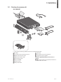
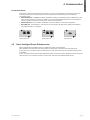
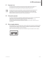
3.2 Checking the accessory kit
9PX 3000GLRT
3. Installation
14
19
25
26
24
20
21 2322
15
17
18
14
9PX UPS
15
Connection cable to AC-power source
17
RS232 communication cable
18
USB communication cable
19
Cable locking system
20
Manual CD-ROM
21
Software leaflet
22
Safety instructions
23
Quick start
24
Mounting kit for 19-inch enclosures
25
2 supports for tower position
Elements supplied depending on the version or
optional
26
NMC communication card (optional, standard on
Network Bundle models)
• Verify that the following additional items are included with the UPS:

Page 20
9PX 1-3 KVA US_EN
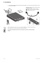
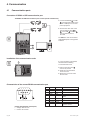
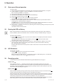
3. Installation
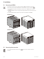
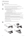
• If you ordered an optional Extended Battery Module (EBM), verify that the following additional items are
included with the EBM:
3
4
2
1
1
Battery power cable with attached battery
detection cable
2
Stabilizer bracket (4 screws included)
3
Rack kit for 19-inch enclosures (optional)
4
EBM Installation manual.
Discard the EBM user’s guide if you are installing the EBM with a new UPS at the same time.
Use the UPS user’s guide to install both the UPS and the EBM.
If you ordered other UPS accessories, refer to specic user manuals to check the packing
contents.
Page is loading ...
Page is loading ...
Page is loading ...
Page is loading ...
Page is loading ...
Page is loading ...
Page is loading ...
Page is loading ...
Page is loading ...
Page is loading ...
Page is loading ...
Page is loading ...
Page is loading ...
Page is loading ...
Page is loading ...
Page is loading ...
Page is loading ...
Page is loading ...
Page is loading ...
Page is loading ...
Page is loading ...
Page is loading ...
Page is loading ...
Page is loading ...
Page is loading ...
Page is loading ...
-
 1
1
-
 2
2
-
 3
3
-
 4
4
-
 5
5
-
 6
6
-
 7
7
-
 8
8
-
 9
9
-
 10
10
-
 11
11
-
 12
12
-
 13
13
-
 14
14
-
 15
15
-
 16
16
-
 17
17
-
 18
18
-
 19
19
-
 20
20
-
 21
21
-
 22
22
-
 23
23
-
 24
24
-
 25
25
-
 26
26
-
 27
27
-
 28
28
-
 29
29
-
 30
30
-
 31
31
-
 32
32
-
 33
33
-
 34
34
-
 35
35
-
 36
36
-
 37
37
-
 38
38
-
 39
39
-
 40
40
-
 41
41
-
 42
42
-
 43
43
-
 44
44
-
 45
45
-
 46
46


Eaton 9PX 1000 GRT Installation and User Manual
- Type
- Installation and User Manual
Ask a question and I''ll find the answer in the document
Finding information in a document is now easier with AI
Related papers
-
Eaton 9EEBM240 User manual
-
Eaton 5P1500R-L User manual
-
Eaton 9PX EBM 180V User guide
-
-
-
MGE UPS Systems EX 3000 RT3U HotSwap HW User manual
-
-
-
-
Eaton 9PX EBM 240V User manual
Other documents
-
 PowerWalker VFI 1500 RT HID Owner's manual
-
Magic Chef MCAR170B2 User guide
-
 Centralion ENDURE 1000VA User manual
-
 BlueWalker 1000VA User manual
-
 Power Walker 1000VA User manual
-
iON F-16 User manual
-
BlueWalker 10120535 Datasheet
-
 PowerWalker VFI 1500RT User manual
-
PowerWalker Basic VI User manual
-
 BlueWalker PowerWalker VI 1500RT LCD/UK User manual


