Page is loading ...

Schnellstartanleitung IRF14x1
DZ-HAND-91072-0/A 2019-11-11 V1.0 © ads-tec Industrial IT GmbH • Heinrich-Hertz-Str. 1 • 72622 Nürtingen • Germany
1. Sicherheit
ACHTUNG
Personen- und Sachschäden durch unsachgemäße
Handhabung
Montage- und Servicearbeiten am Gerät sind nur in
gesichertem und spannungsfreiem Zustand erlaubt!
Hinweis:
Achten Sie bei der Handhabung elektrostatisch
gefährdeter Bauteile auf die relevanten
Sicherheitsmaßnahmen gemäß DIN EN 61340-5-1/-2.
1 x Industrial Router & Firewall Typ IRF14x1
1 x 4-poliger Stecker für Spannungsversorgung und digitalen Eingang
1 x 3-poliger Stecker für RS-485
1 x Schnellstartanleitung (dieses Dokument)
Optional:
1 x Mobilfunkantenne
Verwendet werden können SIM-Karten und Smartcards (SC) im Format
ID-000 gemäß ISO 7816 (25x15 mm).
Die SIM-Karte für den Mobilfunk muss im oberen Steckplatz (SIM1)
gesteckt werden.
Die Smartcard (128 kB) ist für ein Backup der Konfigurationsdaten oder
für die Verbindung zu Big-LinX vorgesehen und muss im unteren Steckplatz
gesteckt werden.
• Stecken Sie die Karte(n) in der gezeigten Ausrichtung in den
Doppelschacht.
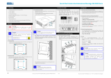
4.1 An Hutschiene anbringen
1. Setzen Sie die IRF von unten schräg an der Hutschiene an (1).
2. Ziehen Sie die Hutschienenverriegelung (2) mit einem Schraubendreher nach
oben, drücken das Gerät oben an die Hutschiene und entfernen den
Schraubendreher.
3. Die Hutschienenverriegelung springt in ihre Ausgangsposition zurück.
4. Überprüfen Sie den Sitz der IRF an der Hutschiene.
4.2 Von Hutschiene lösen
Um die IRF von der Hutschiene zu lösen, ziehen Sie die
Hutschienenverriegelung (2) mit einem Schraubendreher nach oben und
kippen das Gerät nach schräg unten weg.
4.3 Optional: Mobilfunkantenne anbringen
Schrauben Sie die Mobilfunkantenne direkt oder
über ein SMA-Verlängerungskabel auf den
Antennenanschluss.
5.1 Spannungsversorgung
DI Digitaler Eingang (Funktion konfigurierbar)
FE Funktionserde (erforderlich für EMV)
0V Bezugspotenzial 0 V
V+ Versorgungsspannung +24 VDC ± 20 %
5.2 RS-485 (EIA-485) für Modbus-RTU
Der Feldbusknoten ist galvanisch getrennt von der Spannungsversorgung der IRF.
Seine elektrische Busbelastung beträgt 1/8 Einheit (Unit load = 1/8).
GND Bezugspotenzial (Common) für die Datensignale
D- Invertiertes Datensignal
D+ Nicht-invertiertes Datensignal
6.1 IRF an einen PC anschließen
Für die Erstinbetriebnahme muss die IRF an einen PC angeschlossen werden.
Verbinden Sie den Anschluss LAN1 der IRF mithilfe eines Patchkabels mit Ihrem PC.
6.2 Konfiguration des LAN-Netzwerkadapters Ihres PCs
Öffnen Sie die Eigenschaften-Karte des verwendeten Netzwerkadapters und tragen folgende
Parameter ein:
IP-Adresse: 192.168.0.100
Subnetzmaske: 255.255.255.0
Die letzte Ziffernfolge muss eine Zahl zwischen 1 und 253 sein, in diesem Beispiel „100“.
6.3 Aufruf des Webinterface der IRF
Um das Webinterface des Geräts zu öffnen, starten Sie Ihren Web-Browser.
Geben Sie folgende IP-Adresse in die Adresszeile des Browsers ein:
http://192.168.0.254
Bestätigen Sie Ihre Eingabe. Das Webinterface des Geräts öffnet sich.
Folgen Sie den Anweisungen des Inbetriebnahme-Assistenten.
Weitere Informationen sowie Zubehör finden Sie auf unserer Website
www.ads-tec.de
4. Montage
5. Installation
2. Lieferumfang
3. Optional: SIM-Karte / Smartcard einlegen
6. Erstinbetriebnahme

Quick Start Guide IRF14x1
DZ-HAND-91072-0/A 2019-11-11 V1.0 © ads-tec Industrial IT GmbH • Heinrich-Hertz-Str. 1 • 72622 Nürtingen • Germany
1. Safety
ATTENTION
Personal injuries and damage to property through
improper use
All installation and service work performed on the
device must be performed only under safe, secure and
de-energised conditions!
Note:
Always adhere to the safety measures applicable
when handling components at risk of being damaged
by electrostatic discharges in accordance with
EN 61340-5-1/-2.
1 x Industrial router and firewall, type IRF14x1
1 x 4-pin plug for power supply and digital input
1 x 3-pin plug for RS-485
1 x Quick-start guide (this document)
Optional:
1 x Mobile communications antenna
SIM cards and smart cards (SC) in the ID-000 format as defined in
ISO 7816 (25x15 mm) can be used.
The SIM card for mobile communications must be inserted into the top slot
(SIM1).
The smart card (128 kB) is intended for backing up the configuration data
or for connecting to Big-LinX and must be inserted into the bottom slot.
• Insert the card(s) into the dual slot the right way round as shown in the
figure.
4.1 Attaching to top-hat rail
1. Position the IRF on the top-hat rail from below at an angle (1).
2. Pull the top-hat rail locking mechanism (2) upwards using a screwdriver, push
the device from above onto the top-hat rail and remove the screwdriver.
3. The top-hat rail locking mechanism springs back to its original position.
4. Check that the IRF is seated securely on the top-hat rail.
4.2 Detaching from top-hat rail
To detach the IRF from the top-hat rail, pull the top-hat rail locking mechanism
(2) upwards using a screwdriver and remove the device downwards at an angle.
4.3 Optional:
Attaching mobile communications antenna
Screw the mobile communications antenna to
the antenna connection directly or via an
SMA extension cable.
5.1 Power supply
DI Digital input (function configurable)
FE Functional earth (required for EMC)
0V Reference potential 0 V
V+ Supply voltage +24 VDC ± 20 %
5.2 RS-485 (EIA-485) for Modbus RTU
The fieldbus node is electrically isolated from the power supply of the IRF.
Its electrical bus load is 1/8 unit load.
GND Reference potential (common) for the data signals
D- Inverted data signal
D+ Non-inverted data signal
6.1 Connecting IRF to PC
During initial setup, the IRF must be connected to a PC. Connect the connection LAN1 of the
IRF to your PC using a patch cable.
6.2 Configuring LAN network adapter of your PC
Open the Properties of the used network adapter and enter the following parameters:
IP address: 192.168.0.100
Subnet mask: 255.255.255.0
The last set of digits must be a number between 1 and 253. In this example, "100".
6.3 Calling web interface of IRF
To access and open the device web interface, start up your web browser.
Enter the following IP address in the address field of the browser:
http://192.168.0.254
Confirm your entries. The web interface of the device opens.
Follow the instructions of the setup wizard.
Further information as well as accessories can be found on our website
www.ads-tec.de
4. Assembly
5. Installation
2. Scope of delivery
3. Optional: Inserting SIM card / smart card
6. Commissioning
/