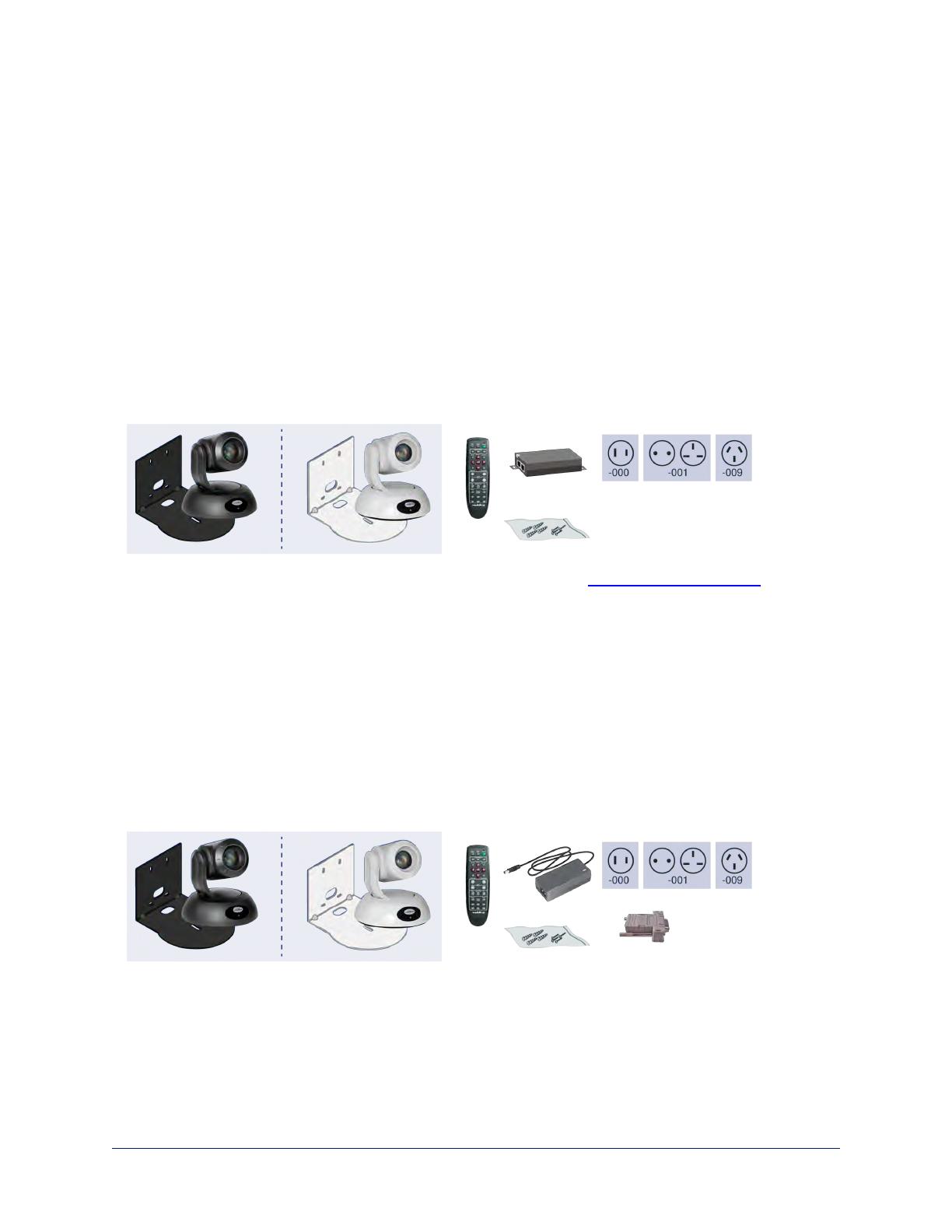
RoboSHOT 30E SDI, North America – 999-99330-000 (black)
RoboSHOT 30E SDI, North America – 999-99330-000W (white)
RoboSHOT 30E SDI, Europe/UK – 999-99330-001 (black)
RoboSHOT 30E SDI, North America – 999-99330-001W (white)
RoboSHOT 30E SDI, Australia/New Zealand – 999-99330-009 (black)
RoboSHOT 30E SDI, North America – 999-99330-009W (white)
n RoboSHOT 30E SDI camera
n Thin Profile Wall Mount with mounting hardware, black or white, depending on camera color
n Vaddio IR Remote CommanderThin Profile Wall Mount with mounting hardware, black or white,
depending on camera color
n PoE+ mid-span power injector with AC cord set(s)
n Quick-Start Guide
Note
If you need an EZCamera RS-232 Control Adapter for use with this camera, please contact Vaddio
Technical Support to obtain one.
Download manuals, dimensional drawings, and other information from www.vaddio.com/support.
RoboSHOT 30 HD-SDI, North America – 999-9933-000 (black)
RoboSHOT 30 HD-SDI, North America – 999-9933-000W (white)
RoboSHOT 30 HD-SDI, Europe/UK – 999-9933-001 (black)
RoboSHOT 30 HD-SDI, North America – 999-9933-001W (white)
RoboSHOT 30 HD-SDI, Australia/New Zealand – 999-9933-009 (black)
RoboSHOT 30 HD-SDI, North America – 999-9933-009W (white)
n RoboSHOT 30 HD-SDI camera
n Thin Profile Wall Mount with mounting hardware, black or white, depending on camera color
n Vaddio IR Remote Commander
n EZCamera RS-232 Control Adapter (998-1001-232)
n 12 VDC, 3.0 A switching power supply with AC cord set(s)
n Quick-Start Guide
4
Complete Manual for RoboSHOT HD-SDI and SDIProfessional A/V Presentation Cameras


