Page is loading ...

INSTALLATION AND USER INSTRUCTION GUIDE
Electric Insert Heater
Model No (s)
F22L**RU
F26L**RU
F33L**RU
*O denotes colour of trim
*D denotes colour of trim on models with openable doors
Electric Heater
This guide should be used to install and care for your
Flavel Electric heater.
Read all information carefully prior to
installation and use.

Installation
IMPORTANT Please read the instructions below before
installation or use of this Flavel Electric Heater.
NEVER use this heater where it may come into contact with water
i.e. bathroom, shower room, kitchen.
NEVER leave unsupervised children where the heater is left
switched ON or is left unguarded.
NEVER use this heater beneath a fixed socket
outlet.
NEVER cover or obstruct the fan outlet, as this
will cause the appliance to overheat.
NEVER install the heater close to combustible
materials i.e. curtains or similar. Allow a
minimum of one metre around the heater.
NEVER route the mains cable beneath carpet.
NEVER use aerosols or similar close to the heater.
NEVER use the heater to dry clothes or similar.
NEVER use the heater by means of an automatic
control or timer, as this may cause risk of
fire if the heater is moved or covered.
NEVER fit the heater directly onto carpet or similar
material. It should be fitted onto a suitable
non-combustible hearth
The appliance MUST
be disconnected from the mains supply before
commencing cleaning, or maintenance.
Ensure the heater is firmly secured to the fixing plain to
prevent it from falling forward.
Use a suitable fireguard to protect both the infirm and young children
who could come into contact with the heater.
DO NOT COVER
1

Appliance Data
Supply Voltage 230V ac, 50Hz
Fuse Rating 13 Amp
Heating Element 2 x 1kW
Mains Cable 1 x 1.8M PVC 1mm
2
Illumination 2 x 60W for F22L**RU & F26L**RU
3 x 60W for F33L**RU
The Flavel Electric Heater is manufactured by: -
CFM Europe Limited
Trentham Lakes
Stoke on Trent
Staffordshire ST4 4TJ
Installation Requirements
The Flavel Electric heater is supplied with a moulded two pin plug (13
Amp) and approximately 1.8 metres of flexible mains cable (1mm
2
). The
appliance and surround should therefore be located close to a suitable
mains socket to enable connection. The electrical socket MUST be easily
accessible to allow disconnection.
This heater MUST be earthed. If in any doubt consult a suitable competent
person.
Connections
L = Brown N = Blue E = Green / Yellow
Before use ensure that the supply voltage matches that marked on the
appliance.
The mains cable should be routed from the heater to the socket
connection without being trapped or being liable to damage. If the supply
cord is damaged, it must be replaced by the manufacturer, its service
agent or similarly qualified persons in order to avoid hazard.
2

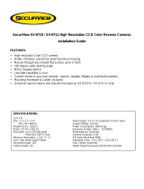
The heater is suitable for installation into proprietary surrounds that have
an opening size within the guidelines shown below in Fig. 1:
REF F22L**RU F26L**RU F33L**RU
A 617mm 719mm 896mm
B 537mm 651mm 753mm
C 559mm 660mm 838mm
D 508mm 622mm 737mm
E 307mm 307mm 307mm
F 559mm 457mm 639mm
G 540mm 641mm 819mm
H 381mm 495mm 578mm
3
A
G
H
D
B
E
F
C
Fig. 1

If fitted into an open draught type fireplace or chimney then it may be
advisable to blank off the aperture to reduce the amount of draught
created through the fireplace, which can cause operation of the safety
cut-out.
Unpacking The Appliance
The Flavel Electric heater is supplied in a single pack carton. All
Instructions should be read prior to unpacking or installing the appliance.
Ensure all parts including loose items have been removed prior to
discarding the packaging.
Product Checklist
1off Flavel Electric Heater Main Body with Emberbed Fitted
1off Magnetic Trim Assembly and Magnets
1off Logset
1off Remote Control Handset & 2 off AAA Batteries
1off Installation & User Instruction Book / Guarantee Literature
Appliance Fixing
The heater must be fixed into position using the fixing method detailed
below:
The appliance may be secured using the four No.12 x 40mm screws and
rawlplugs supplied.
Heater Assembly
Decorative Trim
Remove the protective tape from the decorative trim(s) and position onto
the fixing flange. The trim is secured with the 4 magnets supplied.
4

Removing the Glass Panel (Models with non opening
doors)
a) Push spring loaded clips inwards
b) Lift glass panel clear
Removing the Glass Panel (Models with openable doors)
a) Locate and remove the top retaining screws
b) Undo the hinge screws at the bottom ensuring that you maintain a
grip on the doors at all times to prevent them from falling when the
hinge screws are released.
c) Re-assemble in reverse order
Fitting the Logset
a) Remove the glass panel and or doors as detailed above.
b) Fit the log set to the emberbed as shown below in Fig. 2 :-
Fig. 2
Position behind retaining
lugs
5

Operation Of The Heater
The heater is operated via the use of the remote control handset as
supplied. (See Fig. 3 below for button layout)
a.) To operate the light effect only, press the transmit button and the light
only effect button at the same time. (See Fig. 3 for button layout)
b) To operate the 1kW Heater, press the transmit button and the small
flame button at the same time. (See Fig. 3 for button layout)
c) To operate the 2kW Heater, press the transmit button and the large
flame button at the same time. (See Fig. 3 for button layout)
d) To turn the light effect and heater off, press the off button. (See Fig. 3
for button layout)
IMPORTANT : Safety Cut Out
This appliance is fitted with an automatic safety cut out. This operates if
the air outlet beneath the canopy becomes covered or blocked. This will
prevent the fan heater from operating.
In order to RESET the appliance the following procedure should be
followed:-
a) Switch OFF the appliance and disconnect the appliance from the
mains supply
6
2 kW Heater Button
(Large Flame)
1 kW Heater Button
(Small Flame)
Light Only Effect
Off Button
Transmit Button
Fig. 3

b) Leave the appliance disconnected for a MINIMUM of 10mins
c) Check the appliance is free from all obstructions and remove safely
d) Switch ON the appliance at the mains supply socket
e) Operate the appliance as shown on the previous page
If the appliance fails to operate, repeat the above procedure ENSURING
the appliance is disconnected from the mains supply at the wall socket.
If after repeating this procedure the appliance fails to operate CHECK the
fuse within the wall socket / plug. If after carrying out both of the above
procedures the appliance still fails to operate, then call a suitably qualified
person or CFM Europe Ltd. Service Centre on the number shown on the
rear cover of this booklet.
Care and Cleaning
Always disconnect the appliance from mains supply and allow to cool
before any cleaning operation begins.
Metal painted parts may be cleaned using a clean, damp cloth.
Never use any abrasive cleaners and chemical agents as damage may
occur to the paint finish.
Maintenance
WARNING
BEFORE CARRYING OUT ANY MAINTENANCE, ENSURE
THAT THE APPLIANCE IS DISCONNECTED FROM THE
MAINS ELECTRICAL SUPPLY. IF IN DOUBT SEEK THE
ASSISTANCE OF A SUITABLY QUALIFIED
PERSON.
7

It is advisable to use genuine Flavel replacement parts available from your
supplier or direct from CFM Europe Ltd. (Contact details on the rear of this
booklet)
Bulb Replacement
Flame Effect Bulbs
a) Disconnect the appliance from the mains supply.
b) Remove the glass panel or doors as required
c) Remove the logset
d) Remove the emberbed by removing the retaining screws and
brackets as shown below. Ensure brick sides are held in position
during removal of these brackets. See fig. 4 below
e) The bulbs are located at the rear of the lower assembly, as shown
above in Fig. 5 Replace as necessary using the correct bulb type
and wattage.
f) Re-assemble in reverse order.
Spare Parts List
22 inch Logset 1000-6711 22 inch Emberbed 1000-5438
26 inch Logset 1000-6711 26 inch Emberbed 1000-6710
33 inch Logset 1000-6532 33 inch Emberbed 1000-6526
Bulb B-86900 Element B-82860
Fan Assembly B-67210
Flame effect motor B-87190
Electronic Control Board B-86610
8
Emberbed / Brick side
retaining brackets
Flame effect bulbs
located at rear of
heater
Fig. 4 Fig. 5

CONTACT INFORMATION
Technical Queries
01782 339000
Service / Fault Enquires
08700 101187
The Following Information May Be Required When Contacting Flavel For
Advice :-
Address
Postcode
Model No.
Serial No
Fault
The products serial number and model number can be found on the rating
plate which is affixed to the bottom L/H side of the front panel, behind the
ashpan cover.
Due to our policy of continual improvement and development the exact
accuracy of descriptions and illustrations cannot be guaranteed.
Part No. B-89970
Issue 1
CFM Europe Ltd
Trentham Lakes
Stoke-on-Trent
Staffordshire
ST4 4TJ
Telephone 01782 339000
www.cfm-europe.com


/