Page is loading ...

ADBS-4x1-39TW Page 1 of 4
Installation Guide
ADBS-4x1-39TW
4 x 1 Wall Menu Board Tilt
REQUIRED TOOLS
OPTIONAL TOOLS
• Power driver
• 13mm Hex socket
• Crosshead Screwdriver
• Spirit Level
INSTALL GUIDELINES
TWO PERSON INSTALL RECOMMENDED.
• Read and understand Installation Safety Instructions before commencing installation.
• Atdec recommends that a professional AV installer or other suitably qualified person
install this product.
• Configurations should be installed in a symmetrical manner for optimal safety.
• Place rail supports (ADB-RPJ, ADB-RUJ, ADB-WP) evenly along the length of a Rail
segment to provide even loading of components.
• ADB-R175 requires two rail supports (ADB-RPJ, ADB-RUJ, ADB-WP) to support a load
of 200lbs (100kg). If one rail support is used, the rail can only support 110lbs (50kg)
maximum load.
• Fasten ADB-RX symmetrically over the junction of Rail segments. Tighten the set screws
of ADB-RX firmly.
• Place ADB-WP Wall Plates directly behind the centre of each screen.
• ADB-RX must never be used as the sole support for any Rail segment. The ADB-RX is for
alignment purposes only and is not to bear load. All Rail segments must be supported by
at least one ADB-WP Wall Plate.
• When attaching displays, attach in an order that ensures stability during installation.
Alternate the loading order such that loads are balanced across to system. Alternate
the side onto which screens are placed to distribute load evenly.
• ADB-R48 must be placed in the centre of the rail segments and supported by an
ADB-WP Wall Plate.

ADBS-4x1-39TW Page 2 of 4
COMPONENT & PARTS CHECKLIST
D
E
ADB-WP Wall Plate QTY:5
Ref Part name Qty
D1 Wall Plate 1
D2 M8 x 12mm Screw 4
D3 M8 Washer 4
D4 M8 Nut 4
D5 M8 Washer 2
D6 Coach Screw 2
D7 Plastic Anchor 2
D8 5mm Allen Key 1
ADB-B400T VESA 400 Tilt Brackets
QTY:4
Ref Part name Qty
E1 Tilt Bracket - Right 1
E2 Tilt Bracket - Left 1
E3 M5 x 15mm Screw 4
E4 M6 x 15mm Screw 4
E5 M8 x 15mm Screw 4
E6 M6 Washer 4
D2
D1
D3 D4
D5 D6 D7 D8
A1
A2
A3
E2E1
E3 E4
E5 E6
A
ADB-R175-S 175 Rail QTY:2
Ref Part name Qty
A1 Rail, 68.90” (1750mm) 1
A2 End Cap 2
A3 M5 x 8mm Screw 2
220lbs
100kg
220lbs
100kg
110lbs
50kg
B
ADB-R48 48 Rail QTY:1
Ref Part name Qty
B1 Rail, 18.90” (480mm) 1
B2 End Cap 2
B3 M5 x 8mm Screw 2
B1
B2
B3
220lbs
100kg
C
ADB-RX Rail Extension Kit QTY:2
Ref Part name Qty
C1 Rail Extender Bar 1
C2 M6 x 8mm Set Screw 4
C3 3mm Allen Key 1
C1
C2
C3

ADBS-4x1-39TW Page 3 of 4
INSTALLATION SAfETY INSTRUCTIONS
CAUTION: THIS MOUNT IS INTENDED fOR USE ONLY UP TO THE
MAXIMUM WEIGHTS INDICATED. USE WITH DISPLAYS HEAVIER THAN
THE MAXIMUM INDICATED MAY RESULT IN INSTABILITY OR fAILURE
CAUSING POSSIBLE INJURY, DEATH OR DAMAGE TO EQUIPMENT.
Do not attempt to install this product until all instructions
and warnings have been read and properly understood.
If you have any questions regarding any of the instructions
or warnings, please contact Atdec customer service.
Please keep this information for future reference.
Please check carefully to make sure there are no missing
or defective parts - defective parts must never be used.
Never operate this mounting system if it is damaged.
Return the mounting system to a service centre for
examination and repair.
Atdec, its distributors and dealers are not liable or
responsible for damage or injury caused by improper
installation, improper use or failure to observe these
safety instructions. Use this mounting system only for its
intended use as described in these instructions. Do not
use attachments not recommended by the manufacturer.
In such cases, all guarantees will expire.
GENERAL
This product should only be installed by someone of
good mechanical aptitude, who has experience with
basic building construction, and fully understands these
instructions. Atdec recommends that a professional
AV installer or other suitably qualified person install
this product. Great care must always be taken during
installation as most AV equipment is of a fragile nature,
possibly heavy and easily damaged if dropped. Always
use an assistant or mechanical lifting device to safely lift
and position equipment.
If you do not fully understand the instructions or are not
sure how to install this product safely, then please consult
a professional for advice and/or to install this product for
you. Failure to mount this product correctly may cause
serious injury or death both during installation and at any
time thereafter.
Do not mount any AV equipment that exceeds the specific
weight limit of the product you are installing.
PRODUCT LOCATION
Please pay careful attention to where this product is
located. Check load capacity of wall prior to installation
as some mounting surfaces (including walls, ceilings,
horizontal surfaces) are not suitable for installation.
Failure to provide adequate structural strength for
this component can result in serious personal injury or
damage to equipment! It is the installer’s responsibility
to make sure the structure to which this component is
attached can support five times the combined weight
of all equipment. Reinforce the structure as required
before installing the component. Installing on drywall
boards alone will not support the weight of most AV
equipment. If you install this product on drywall it must be
securely fixed to a wooden stud, concrete block or other
permanent structure behind the drywall board.
Designed for indoor use, this mount is suitable for public
or home installation. If located in a public or frequently
populated area ensure that the product is out of the
immediate reach of people. If any AV equipment is to
be suspended over the likely path or location of people
then great care should be taken to secure all parts of the
installation from falling.
When drilling holes in walls it is essential to avoid
contact with electrical cables and water or gas pipes
contained within. Use of a good quality live wire detector
and hidden object locator is therefore recommended.
Only drill into structures when you are sure it is safe
to do so.
fIXING HARDWARE
The installer must be satisfied that any supplied fixing
hardware is suitable for each specific installation. If any
fixing screws or included hardware are deemed not
sufficient for a safe installation then please consult a
professional or your local hardware store.
It is highly recommended that all wall fixing screws be
used where supplied and that the purpose of all other
fixing hardware is fully understood. In some cases more
AV equipment fixing hardware will be supplied
to accommodate different models of equipment and
set up configurations.
HAzARD LIMITATION
When routing cables take advantage of any built in
cable management features that the product might
provide and ensure that all cables are tidy and secure.
Check to see that any moving aspect of product can
do so unhindered by any cabling.
Some products have moving parts and the potential
to cause injury through the crushing or trapping of
fingers or other body parts.
Particular attention to the nature of moving parts is
required especially when assembling, installing and
adjusting during set up. Immediately after installations
double-check that the work done is safe and secure.
Double-check all necessary fixings are present and are
of ample tightness.
Tighten screws so adaptor brackets are firmly attached.
Do not tighten with excessive force. Overtightening
can cause stress damage to screws, greatly reducing
their holding power and possibly causing screw heads
to become detached. Tighten to 4.5N/m or 40 in-lb
maximum torque.
Correct length screws must be used. If screws don’t get
three complete turns in the screen inserts or if screws
bottom out and bracket is still not tightly secured,
damage may occur to screen or product may fail.
It is recommended that periodic inspections of the
product and its fixing points are made to ensure that
safety is maintained. If in doubt consult a professional
AV installer or other suitably qualified person.

ADBS-4x1-39TW Page 4 of 4
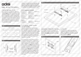
INSTALLATION INSTRUCTIONS
1. Attach wall plates to rail. Make note
of stud or other mounting point when
positioning plates on rail
3. Attach brackets to screen with supplied
screws and spacers (if required)
Fasten ADB-RX on both sides of the rail
6. Tighten or loosen screw to raise or
lower screen height, respectively
2A.
4. Attach brackets to screen with supplied
screws and spacers (if required)
7. Safety screw 8. Put screw into hole to set at required
angular increment
2B.
5. Carefully lower brackets onto the rail,
one at a time.
a. b.
Wood Stud Concrete
5˚
10˚
15˚
Put screw into hole
to set at required
angular increment
D1
D3
D2
A1
B1
E1
E2
E3,4,5
E1
E2
D5
D6
D5
D6
D7
D4
A1 B1
a. b.
Wood Stud Concrete
5˚
10˚
15˚
Put screw into hole
to set at required
angular increment
D1
D3
D2
A1
B1
E1
E2
E3,4,5
E1
E2
D5
D6
D5
D6
D7
D4
A1 B1
a. b.
Wood Stud Concrete
5˚
10˚
15˚
Put screw into hole
to set at required
angular increment
D1
D3
D2
A1
B1
E1
E2
E3,4,5
E1
E2
D5
D6
D5
D6
D7
D4
A1 B1
a. b.
Wood Stud Concrete
5˚
10˚
15˚
Put screw into hole
to set at required
angular increment
D1
D3
D2
A1
B1
E1
E2
E3,4,5
E1
E2
D5
D6
D5
D6
D7
D4
A1 B1
a. b.
Wood Stud Concrete
5˚
10˚
15˚
Put screw into hole
to set at required
angular increment
D1
D3
D2
A1
B1
E1
E2
E3,4,5
E1
E2
D5
D6
D5
D6
D7
D4
A1 B1
a. b.
Wood Stud Concrete
5˚
10˚
15˚
Put screw into hole
to set at required
angular increment
D1
D3
D2
A1
B1
E1
E2
E3,4,5
E1
E2
D5
D6
D5
D6
D7
D4
A1 B1
a. b.
Wood Stud Concrete
5˚
10˚
15˚
Put screw into hole
to set at required
angular increment
D1
D3
D2
A1
B1
E1
E2
E3,4,5
E1
E2
D5
D6
D5
D6
D7
D4
A1 B1
a. b.
Wood Stud
Concrete
5˚
10˚
15˚
Put screw into hole
to set at required
angular increment
D1
D3
D2
A1
B1
E1
E2
E3,4,5
E1
E2
D5
D6
D5
D6
D7
D4
A1 B1
a. b.
Wood Stud
Concrete
5˚
10˚
15˚
Put screw into hole
to set at required
angular increment
D1
D3
D2
A1
B1
E1
E2
E3,4,5
E1
E2
D5
D6
D5
D6
D7
D4
A1 B1
atdec.com | atdec.co.uk | atdec.com.au
No portion of this document or any artwork contained herein should be reproduced in any way without
the express written consent of Atdec Pty Ltd. Due to continuing product development, the manufacturer
reserves the right to alter specifications without notice. ©20181220A
Fix symmetrically
/