Zanussi ZGG642CN User manual

Category
Hobs
Type
User manual

This manual is also suitable for

Zanussi ZGG642CN is a gas hob with four burners of different sizes and power levels, allowing you to cook a variety of dishes simultaneously. It features easy-to-use control knobs for precise flame adjustment, ensuring optimal cooking results for various foods. The hob's durable construction and easy-to-clean surface make it both practical and long-lasting.

Zanussi ZGG642CN is a gas hob with four burners of different sizes and power levels, allowing you to cook a variety of dishes simultaneously. It features easy-to-use control knobs for precise flame adjustment, ensuring optimal cooking results for various foods. The hob's durable construction and easy-to-clean surface make it both practical and long-lasting.

GAS HOB
ZGG 642
INSTRUCTION BOOKLET
Please read this instruction booklet before using the appliance
GB
2
Important Safety Information
You MUST read these warnings carefully before installing or using the hob. If you need
assistance, contact our Customer Care Department on
08705 727 727.
Installation
This appliance must be installed and serviced by a
competent person as stated in the Gas Safety
(Installation and Use) Regulations Current Editions
and the IEE Wiring Regulations.
z Remove all packaging before using the hob.
z Ensure that the gas and electrical supply complies
with the type stated on the rating plate, located near
the gas supply pipe.
z Do not attempt to modify the hob in any way.
Child Safety
z This hob is designed to be operated by adults. Do
not allow children to play near or with the hob.
z The hob gets hot when it is in use.
z Children should be kept away until it has cooled.
z Children can also injure themselves by pulling pans
or pots off the hob.
z This appliance is not intended for use by children or
other persons whose physical, sensory or mental
capabilities or lack of experience and knowledge
prevents them from using the appliance safely without
supervision or instruction by a responsible person to
ensure that they can use the appliance safely.
During Use
z This hob is intended for domestic cooking only. It is
not designed for commercial or industrial purposes.
z This appliance is not connected to a combustion
products evacuation device. It must be installed and
connected in accordance with current installation
regulations. Particular attention shall be given to the
relevant requirements regarding ventilation.
z When in use a gas cooking appliance will produce
heat and moisture in the room in which it has been
installed. Ensure there is a continuous air supply,
keeping air vents in good condition or installing a
cooker hood with a venting hose.
z When using the hob for a long period of time, the
ventilation should be improved, by opening a window
or increasing the extractor speed.
z Do not use this hob if it is in contact with water.
Do not operate the hob with wet hands.
z Keep the appliance clean. Food residuals increase
the risk of fire.
z Ensure the control knobs are in the ‘OFF’ position
when not in use.
z When using other electrical appliances, ensure the
cable does not come into contact with the hot surfaces
of the cooking appliance.
z Unstable or misshapen pans should not be used on
the hob as unstable pans can cause an accident by
tipping or spillage.
z Never leave the hob unattended when cooking with
oil and fats.
z Never use plastic or aluminium foil dishes on the hob.
z Perishable food, plastic items and areosols may be
affected by heat and should not be stored above or
below the hob unit.
z This appliance cannot be cleaned with steam or with
a steam cleaning machine.
Service
z This hob should only be repaired or serviced by an
authorised Service Engineer and only genuine
approved spare parts should be used.
3
Contents
Keep this instruction book for future reference
and ensure it is passed on to any new owner.
For the User
Important Safety Information 2
Description of the Hob 4
Operation 5
Maintenance and Cleaning 5
Something Not Working? 6
Guarantee/Customer Service 15
European guarantee 16
Environmental Information
z After installation, please dispose of the packaging
with due regard to safety and the environment.
z When disposing of an old appliance, make it unusable,
by cutting off the cable.
z The symbol on the product or on its packaging
indicates that this product may not be treated as
household waste. Instead it shall be handed over to
the applicable collection point for the recycling of
electrical and electronic equipment. By ensuring this
product is disposed of correctly, you will help prevent
potential negative consequences for the environment
and human health, which could otherwise be caused
by inappropriate waste handling of this product. For
more detailed information about recycling of this
product, please contact your local city office, your
household waste disposal service or the shop where
you purchased the product.
Guide to Use the instructions
The following symbols will be found in the text to guide
you throughout the Instructions:
Safety Instructions
Step by step instructions for an operation
Hints and Tips
Enviromental information
)
This appliance complies with the following
E.E.C. Directives:
* 73/23 - 90/683 (Low VoltageDirective);
* 93/68 (General Directives);
* 89/336 (Electromagnetical Compatibility
Directive);
* 90/396 (Gas Appliances),
and subsequent modifications
For the Installer
Engineers technical data 7
Important safety requirements 8
Installation 9
Building In 10
Electrical connections 11
Wiring Diagram 12
Fault Finding 12
Commissioning 14
Conversion from Natural Gas to LPG 14
4
Description of the Hob
1. Semi-rapid Burners
2. Rapid Burner
3. Auxiliary Burner
4. Control knobs
2
1
3
1
4
5
Operation
Hob burners
To light a burner:
z push in the relevant control and turn it to maximum
position;
z then adjust the flame as required.
z If the burner does not ignite, turn the control knob to
zero, and try again.
If you use a saucepan which is smaller than the
recommended size, the flame will spread beyond
the bottom of the vessel, causing the handle to
overheat.
Take care when frying food in hot oil or fat, as
the overheated splashes could easily ignite.
As soon as a liquid starts boiling, turn down the
flame so that it will barely keep the liquid
simmering.
If the control knobs become difficult to turn, please
contact your local Service Centre.
Burner minimum maximum
diameter diameter
Large (rapid) 180 mm. 260 mm.
Medium (semi-rapid) 120 mm. 220 mm.
Small (Auxiliary) 80 mm. 160 mm.
Maintenance and Cleaning
Before any maintenance or cleaning can be carried
out, you must DISCONNECT the hob from the
electricity supply.
The hob is best cleaned whilst it is still warm, as
spillage can be removed more easily than if it is
left to cool.
This appliance cannot be cleaned with steam or
with a steam cleaning machine.
The Hob Top
Regularly wipe over the hob top and the aluminium frame
using a soft cloth well wrung out in warm water to which
a little washing up liquid has been added. Avoid the use
of the following:
- household detergent and bleaches;
- impregnated pads unsuitable for non-stick saucepans;
- steel wool pads;
- bath/sink stain removers.
Should the hob top become heavily soiled, it is
recommended that a cleaning product such as Hob Brite
or Bar Keepers Friend is used.
If scratches or cracks are noticed on the glass
top, immediately disconnect the appliance
from the electrical supply, contact your local
Service Force Centre and avoid using the
appliance until it has been repaired.
Pan Supports
The pan supports are dishwasher proof.
If necessary, remove stubborn stains using a paste
cleaner. Never use steel wool pads or acids.
Pay attention when replacing the pan
supports in order to avoid scratching the glass
hob top.
To ensure maximum burner efficiency, you should only
use pots and pans with a flat bottom fitting the size of
the burner used (see table).
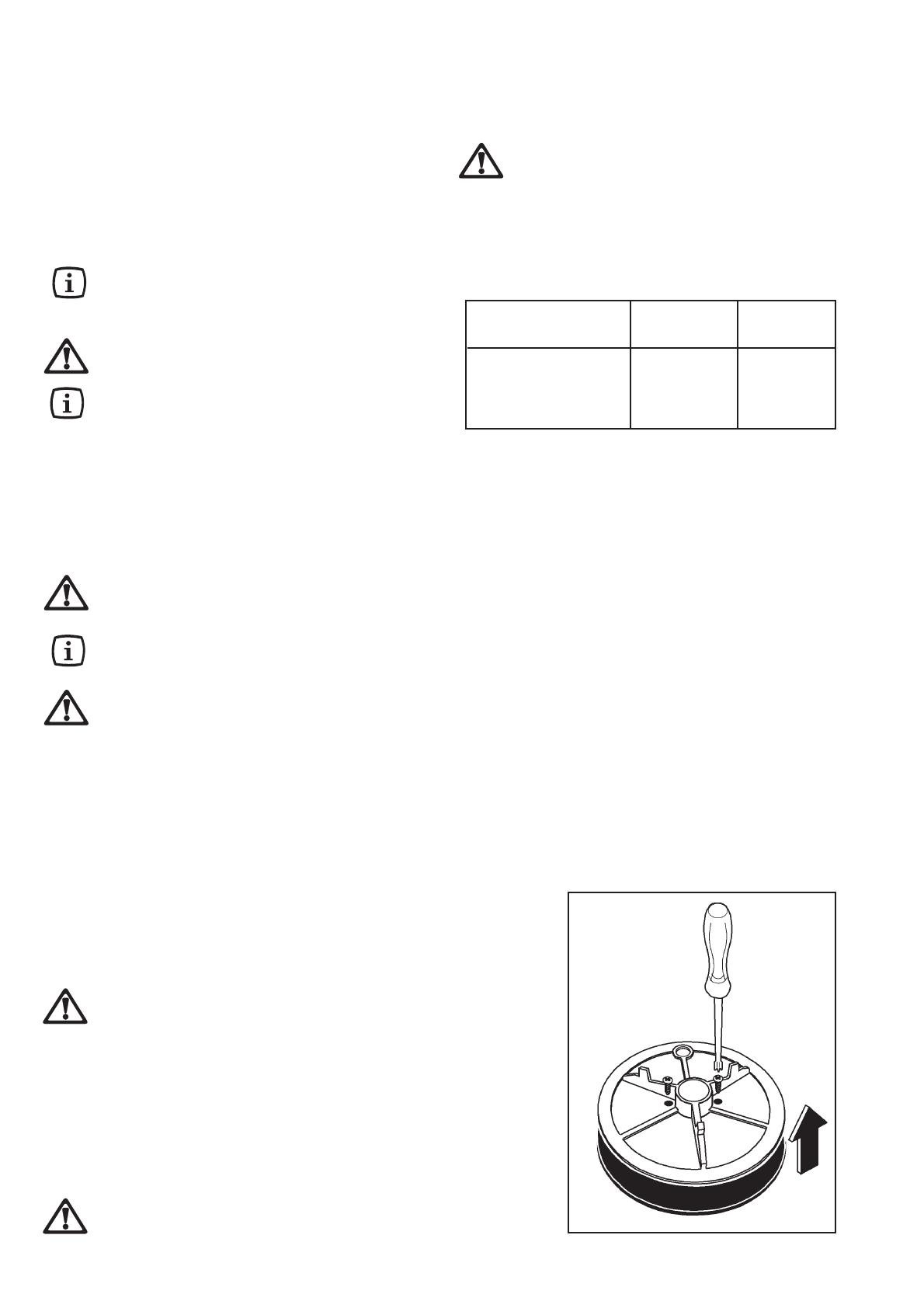
FO 2265
Fig. 1
)
The Burners
The burner caps and crowns can be removed for cleaning.
The cap and crown of each burner are secured with two
screws. To separate the two pieces, lift the crown, turn it
upside down, then undo the two fixing screws as shown
in Fig. 1.
After cleaning, reassemble the two parts and refit the
cap on its correct position on the burner.
Wash the burner caps and crowns using hot soapy water,
and remove marks with a mild paste cleaner. A well
moistened soap impregnated steel wool pad can be used
with caution, if the marks are particularly difficult to
remove.
After cleaning, be sure to wipe dry with a soft cloth.
Avoid cooking with potstones, earthenware
pots or cast iron plates. Also, avoid using
aluminiun foil for protecting the top during
operation.
6
Something Not Working?
If the hob is not working correctly, please carry out the following checks before contacting your local Service Force
Centre.
IMPORTANT:
If you call out an engineer to a fault listed below, or to repair a fault caused by incorrect use or installation,
a charge will be made even if the appliance is under guarantee.
SYMPTOM
There is no spark when lighting the gas
The gas ring burns unevenly
SOLUTION
Check that the unit is plugged in and the electrical
supply is switched on
Check that the RCCB has not tripped (if fitted)
Check the mains fuse has not blown
Check the burner cap and crown have been
replaced correctly, e.g. after cleaning.
Check the main jet is not blocked and the burner
crown is clear of food particles.
Check the burner cap and crown have been
replaced correctly, e.g. after cleaning.
7
OVERALL DIMENSIONS
Width: 580 mm.
Depth: 510 mm.
CUT OUT DIMENSIONS
Width: 550 mm.
Depth: 470 mm.
SUPPLY CONNECTIONS
Gas:
RC 1/2 inch (1/2 inch male) Rear right hand corner
Electric:
230 V 50 Hz supply, 3 core flexible cable with non
rewireable plug fitted with a 3 amp cartridge fuse.
Burner Dia. Tap By-pass
1/100 mm
Auxiliary 28
Semi-rapid 32
Rapid 40
Aeration adjustment none
Instructions for the Installer
Engineers technical data
APPLIANCE CLASS: 3
APPLIANCE CATEGORY: II2H3+
APPLIANCE GAS SUPPLY: Natural gas G20 / 20mbar
Rapid Burner
Heat Input 2.9 kW Natural Gas (9895 BTU/HR)
2.7 kW L.P.G. (9212 BTU/HR)
Semi-rapid Burner
Heat Input 1.9 kW (6483 BTU/HR)
Auxiliary Burner
Heat Input 1.0 kW (3412 BTU/HR)
BURNER RAPID SEMI-RAPID AUXILIARY
(large) (medium) (small)
POSITION MAX MIN MAX MIN MAX MIN
NOMINAL THERMAL
POWER kW 2.9 0.65 1.9 0.45 1.0 0.33
NOMINAL FLOW
RATE m
3
/h 0.276 0.062 0.181 0.043 0.095 0.031
NOZZLE REFERENCE 119 Adjust. 96 Adjust. 70 Adjust.
NOMINAL THERMAL
POWER kW 2.7 0.65 1.9 0.45 1.0 0.33
NOMINAL FLOW
RATE g/h 195 46.8 137 32.4 72 23.8
NOZZLE REFERENCE 86 40 71 32 50 28
NATURAL GAS
20 mbar
TYPE OF
GAS
CHARACTERISTICS
LPG GAS
28-30/37 mbar
1/100 mm
1/100 mm
VALUE = 49.92 MJ/Kg
VALUE = 37.78 MJ/m
3
Ws - 50.7 MJ/ m
3
8
Important safety requirements
This hob must be installed in accordance with the Gas
Safety (Installation and Use) Regulations (Current
Edition) and the IEE Wiring Regulations (Current
Edition).
Detailed recommendations are contained in the
following British Standards Codes Of Practice: B.S.
6172/ B.S. 5440, Part 2 and B.S. 6891 Current Editions.
Provision for Ventilation
The hob should not be installed in a bed sitting room
with a volume of less than 20 m
3
. If it is installed in a
room of volume less than 5 m
3
an air vent of effective
area of 110 cm
2
is required. If it is installed in a room of
volume between 5 m
3
and 10 m
3
an air vent of effective
area of 50 cm
2
is required, while if the volume exceeds
11 m
3
no air vent is required.
However, if the room has a door which opens directly
to the outside no air vent is required even if the volume
is between 5 m
3
and 11 m
3
.
If there are other fuel burning appliances in the same
room, B.S. 5440 Part 2 Current Edition, should be
consulted to determine the requisite air vent
requirements.
FITTING THE GAS HOB
WITHOUT A COOKER HOOD ABOVE
700 mm
400 mm
100 mm
400 mm
50 mm
55 mm
50 mm
FO 0812
FITTING THE GAS HOB
WITH A COOKER HOOD ABOVE
650 mm
400 mm
400 mm
100 mm
50 mm
50 mm
55 mm
600 mm
FO 0813
Location
The hob may be located in a kitchen, a kitchen/diner or
bed sitting room, but not in a bathroom, shower room
or garage.
Before making the cut out in the worktop ensure that
the edges of the hob that are to be near either a side or
rear wall have a minimum distance of 55 mm. between
the edge of the hob and the wall.
The minimum distance combustible material can be
fitted above the hob is 400 mm. If it is fitted below 400
mm. a space of 50 mm. must be allowed from the edges
of the hob.
The minimum distance combustible material can be
fitted directly above the hob is 700 mm. A minimum
distance of 100 mm. must be left between the side
edges of the hob and any adjacent cabinets or walls.
9
A)End of shaft with nut
B) Washer
C) Elbow
FO 0814
FO 0264
Installation
IMPORTANT
This hob must be installed by a competent and
qualified person only.
The manufacturer will not accept liability, should
the above instructions or any of the other safety
instructions incorporated in this book be ignored.
Gas Connection
Connection to the gas supply should be with either rigid
or semi-rigid pipe, i.e. steel or copper.
The connection should be suitable for connecting to RC
1/2 (1/2 BSP male thread).
When the final connection has been made, it is essential
that a thorough leak test is carried out on the hob and
installation. Ensure that the main connection pipe does
not exert any strain on the hob.
It is important to install the elbow correctly, with
the shoulder on the end of the thread, fitted to the
hob connecting pipe.
Failure to ensure the correct assembly will cause
leakage of gas.
WHEN THE HOB IS FIRST INSTALLED
Once the hob has been installed, it is important
to remove any protective materials, which were
put on in the factory.
On the end of the shaft, which includes the GJ 1/2"
threaded elbow, adjustment is fixed so that the washer
is fitted between the components as shown in the
diagram. Screw the parts together without using excessive
force.
Cut Out Size
The dimensions of the cut-out are given in the diagram.
550
470
30
FO 2098
Rectangular cut-out size for hob
Dimensions are given in mm.
10
Building In
Dimensions are given in mm.
Building over a cupboard or
drawer
If the hob is to be installed above a cupboard or drawer
it will be necessary to fit a heat resistant board below
the base of the hob on the underside of the work surface.
It is also recommended to carry out the electrical
connection to the hob as shown in diagrams 1 and 2.
)
FO 2320
Fitting the hob to the worktop
Before fitting the hob into the cut out, an adhesive seal
must be fitted to the underside outside edge (diagram 4)
of the hob. It is essential that no gaps are left in this seal
in order to prevent spillage near the hob seeping into the
cabinet below.
1) Remove the pan supports, the burners caps
and crowns and turn the hob upside down,
taking care the ignition candles are not
damaged in this operation.
2) Place the sealing gasket all around the glass
top edge as shown in diagram 4.
3) Fit the hob in the cut out and push it down
until the glass top and the working top make
contact, as shown in diagram 5.
Building over a kitchen unit with
door
Proper arrangements must be taken in designing the
furniture unit, in order to avoid any contact with the
bottom of the hob which can be heated when it is
operated. The recommended solution is shown in
diagram 3.
The panel fitted under the hob ("a") should be easily
removable to allow easy access if technical assistance
is needed. The space behind the kitchen unit ("b") can
be used for connections.
ON/OFF SWITCH
FLEX
OUTLET
FO 0763
1
FO 1013
3
ON/OFF SWITCH
FLEX
OUTLET
FO 0764
2
A
FO 2107
4
5
A) Sealing gasket
11
)
Electrical connections
Any electrical work required to install this hob
should be carried out by a qualified electrician or
competent person, in accordance with the current
regulations.
THIS HOB MUST BE EARTHED.
The manufacturer declines any liability should these
safety measures not be observed.
This hob is designed to be connected to a 230-240V
50Hz AC electrical supply.
Before switching on, make sure the electricity supply
voltage is the same as that indicated on the hob rating
plate. The rating plate is located on the bottom of the
hob. A copy is attached on the back cover of this book.
The hob is supplied with a 3 core flexible supply cord
incorporating a 3amp plug fitted. In the event of having to
change the fuse, a 3amp ASTA approved (BS 1362) fuse
must be used.
Should the plug need to be replaced for any reason, the
wires in the mains lead are coloured in accordance with
the following code:
Green and Yellow - Earth
Blue - Neutral
Brown - Live
Connect the green and yellow (earth) wire to
the terminal in the plug which is marked with
the letter 'E' or the earth symbol or coloured
green and yellow.
Connect the blue (neutral) wire to the terminal
in the plug which is marked with the letter 'N' or
coloured black.
Connect the brown (live) wire to the terminal in
the plug which is marked with the letter 'L' or
coloured red.
Upon completion there must be no cut, or stray strands
of wire present and the cord clamp must be secure over
the outer sheath.
A cut off plug inserted into a 13 amp socket is
a seriuos safety (shock) hazard. Ensure that
the cut off plug is disposed of safely.
Permanent Connection
In the case of a permanent connection, it is necessary
that you install a double pole switch between the hob
and the electricity supply (mains), with a minimum gap
of 3 mm. between the switch contacts and of a type
suitable for the required load in compliance with the
current electric regulations.
The switch must not break the yellow and green earth
cable at any point.
Ensure that the hob supply cord does not
come into contact with surfaces with
temperatures higher than 50 deg. C.
FO 0390
Min. size Cable/flex Cable / flex type Fuse
0.75 mm
2
H05 V2V2-F (T90) 3 A
Supply cable replacement
The cable used to connect the hob to the electrical supply
must comply to the specifications given below.
12
A. IGNITOR SWITCH
B. IGNITOR UNIT
B
L
N
0
1
2
3
4
5
6
220/240
A
Wiring Diagram
Fault Finding
Preliminary Electrical Systems
Check
A. EARTH CONTINUITY CHECK - Appliance must be
electrically disconnected - meter set on Ω (Ohms) x
1 scale and adjust zero if necessary.
a) Test leads from any appliance earth point to earth
pin on plug. Resistance should be less than 0.1
ý (Ohm), check all earth wires for continuity and
all contacts are clean and tight.
B. INSULATION CHECK - Appliance electrically
disconnected, all switches ON.
a) meter set on Ω (Ohms) x 1 scale.
Test leads from L to N in appliance terminal block.
If meter reads «0» then there is a short circuit.
b) meter set on Ω (Ohm) x 100 scale.
Repeat test with leads from L to E. If meter reads
less than(infinity) there is a fault.
NOTE - Should it be found that the fuse has failed
but no fault is indicated - a detailed continuity check
(i.e. by disconnecting and checking each
component) is required to trace the faulty component.
It is possible that a fault could occur as a result of
local burning/arcing but no fault could be found under
test. However a detailed visual inspection should
reveal evidence of burning around the fault.
START
Isolate appliance
and carry out:
A: Earth Continuity
check.
Has inlet fuse blown?
Carry out:
C: Polarity check.
Electricity supply
should now be
satisfactory.
Carry out:
D: Resistance to
Earth check.
Inlet wiring
faulty.
Rectify any
fault.
Isolate appliance and
carry out:
B: Insulation check.
Rectify any fault
including replacing
fuses as necessary.
SOCKET
(face view)
PLUG (with cover
removed)
Earth Wire
Green/Yellow
Neutral Wire
Blue
Brown
Blue
Green
Yellow
Green
Yellow
Brown
Blue
( )
FUSE
( )
E
N
L
NO
YES
NO YES
13
Ignition System / Gas Ignition
YES
Check plug top fuse
and replace if
necessary
Check polarity and
earth continuity of
supply point
Check earth continuity
of appliance
Ignitor does not spark
Check fitting of burners
Check position of the
electrode
Check by pass simmer
adjusted
Light burner manually
Check gas supply at
burner
Check continuity from 'N' on the
mains connector block and "O" on
the ignitor unit
Check continuity from 'L' on the
mains connector block and the
taps ignition switches
Check continuity from ignition
switches connector to ignitor unit
Check continuity from the tip of
each electrode to the
terminals 1 to 4 on the ignitor
unit
Check for breaks in the
insulation
of the HT leads
Change the taps
ignition switches
NO
Change the ignitor unit
14
Commissioning
When the hob has been fully installed it will be necessary
to check the minimum flame setting. To do this, follow
the procedure below.
- Turn the gas tap to the MAX position and ignite.
- Set the gas tap to the MIN flame position then turn
the control knob from MIN to MAX several times. If
the flame is unstable or is extinguished follow the
procedure below.
Procedure:
Re-ignite the burner and set to MIN.
Remove the control knob.
To adjust, use a thin bladed screwdriver and turn
the adjustment screw (see diagram) until the flame
is steady and does not extinguish, when the knob
is turned from MIN to MAX. Repeat this procedure
for all burners.
Pressure Testing
Remove left hand pan support and front left burner
cap and crown.
Fit manometer tube over the injector.
Turn on the burner gas supply and ignite another
burner.
The pressure reading should be nominally 20mbar
and must be between 17 mbar and 25mbar.
Turn off the burner supplies.
)
)
Conversion from Natural Gas to
LPG
It is important to note that this model is designed for use
with natural gas but can be converted for use with butane
or propane gas providing the correct injectors are fitted.
The gas rate is adjusted to suit.
Method
Ensure that the gas taps are in the 'OFF' position
Isolate the hob from the electrical supply
Remove all pan supports, burner caps, rings, crowns
and control knobs.
With the aid of a 7mm box spanner the burner injectors
can then be unscrewed and replaced by the
appropriate LPG injectors.
To adjust the gas rate
With the aid of a thin bladed screwdriver completely
tighten down the by pass adjustment screw. Upon
completion stick the replacement rating plate on the
under side of the hob.
IMPORTANT
The replacement/conversion of the gas hob should only
be undertaken by a competent person.
Minimum adjustment screw
15
Guarantee/Customer Service
Standard guarantee conditions
We, Zanussi-Electrolux, undertake that if within 12 months of the date of the purchase this Zanussi-Electrolux appliance
or any part thereof is proved to be defective by reason only of faulty workmanship or materials, we will, at our option
repair or replace the same FREE OF CHARGE for labour, materials or carriage on condition that:
· The appliance has been correctly installed and used only on the electricity supply stated on the rating plate.
· The appliance has been used for normal domestic purposes only, and in accordance with the manufacturer’s instruc-
tions.
· The appliance has not been serviced, maintained, repaired, taken apart or tampered with by any person not author-
ised by us.
· Electrolux Service Force Centre must undertake all service work under this guarantee.
· Any appliance or defective part replaced shall become the Company’s property.
· This guarantee is in addition to your statutory and other legal rights.
Exclusions
· Damage or calls resulting from transportation, improper use or neglect, the replacement of any light bulbs or remov-
able parts of glass or plastic.
· Costs incurred for calls to put right an appliance which is improperly installed or calls to appliances outside the
United Kingdom.
· Appliances found to be in use within a commercial environment, plus those which are subject to rental agreements.
· Products of Electrolux manufacturer that are not marketed by Electrolux.
Service and Spare Parts
In the event of your appliance requiring service, or if you wish to purchase spare parts, please contact your local
Service Force Centre by telephoning
0870 5 929 929
Your telephone call will be automatically routed to the Service Force Centre covering your postcode area.
For the address of your local Service Force Centre and further information about Service Force, please visit the
website at
www.serviceforce.co.uk
Before calling out an engineer, please ensure you have read the details under the heading “Something not working”
When you contact the Service Force Centre you will need to give the following details:
1.Your name, address and postcode.
2.Your telephone number.
3. Clear concise details of the fault.
4. The model and Serial number of the appliance (found on the rating plate).
5.The purchase date.
Please note a valid purchase receipt or guarantee documentation is required for in guarantee service calls.
Customer Care
For general enquiries concerning your Electrolux appliance, or for further information on Electrolux products please
contact our Customer Care Department by letter or telephone at the address below or visit our website at
www.electrolux.co.uk
Customer Care Department
Electrolux Major Appliances
Addington Way
Luton
Bedfordshire, LU4 9QQ
Tel: 08705 727 727 (*)
(*) Calls may be recorded for training purposes
16
This appliance is guaranteed by Electrolux in each of the countries listed at the back of this user manual, for the period
specified in the appliance guarantee or otherwise by law. If you move from one of these countries to another of the countries
listed below the appliance guarantee will move with you subject to the following qualifications:
The appliance guarantee starts from the date you first purchased the appliance which will be evidenced by production of
a valid purchase document issued by the seller of the appliance.
The appliance guarantee is for the same period and to the same extent for labour and parts as exists in your new country
of residence for this particular model or range of appliances.
The appliance guarantee is personal to the original purchaser of the appliance and cannot be transferred to another user.
The appliance is installed and used in accordance with instructions issued by Electrolux and is only used within the home,
i.e. is not used for commercial purposes.
The appliance is installed in accordance with all relevant regulations in force within your new country of residence.
The provisions of this European Guarantee do not affect any of the rights granted to you by law.
European guarantee
17
18
19
35690-0402 11/06
Grafiche MDM - Forlì
www.zanussi-electrolux.co.uk
  • Page 1 1
  • Page 2 2
  • Page 3 3
  • Page 4 4
  • Page 5 5
  • Page 6 6
  • Page 7 7
  • Page 8 8
  • Page 9 9
  • Page 10 10
  • Page 11 11
  • Page 12 12
  • Page 13 13
  • Page 14 14
  • Page 15 15
  • Page 16 16
  • Page 17 17
  • Page 18 18
  • Page 19 19
  • Page 20 20

Zanussi ZGG642CN User manual

Category
Hobs
Type
User manual
This manual is also suitable for

Zanussi ZGG642CN is a gas hob with four burners of different sizes and power levels, allowing you to cook a variety of dishes simultaneously. It features easy-to-use control knobs for precise flame adjustment, ensuring optimal cooking results for various foods. The hob's durable construction and easy-to-clean surface make it both practical and long-lasting.

Ask a question and I''ll find the answer in the document

Finding information in a document is now easier with AI