
www.rkiinstruments.com
CO-04C
Operator’s Manual
Part Number: 71-0522
Revision: P2
Released: 5/24/21

2 • 04 Series for CO(-H2)
WARNING
Read and understand this instruction manual before operating
instrument. Improper use of the gas monitor could result in
bodily harm or death.
Maintenance of the gas monitor is essential for proper
operation and correct readings.
Bump test the instrument before each day’s use with a known
concentration of the target gas. A bump test can be done in User
Mode’s BUMP item or by applying gas in Measuring Mode.
The instrument does not need to be calibrated unless it does not
pass the User Mode bump test or does not respond
appropriately, as defined by the user, in Measuring Mode. For
more information about bump test and calibration
requirements, see IEC 60079-29-2.

04 Series for CO(-H2) • 3
Table of Contents
Chapter 1: Introduction . . . . . . . . . . . . . . . . . . . . . . . . . . . . . . . . . . . . . . . . . . . . 6
Overview . . . . . . . . . . . . . . . . . . . . . . . . . . . . . . . . . . . . . . . . . . . . . . . . . . . . . . . . . . . . . . 6
About the CO-04C . . . . . . . . . . . . . . . . . . . . . . . . . . . . . . . . . . . . . . . . . . . . . . . . . . . . . . . 6
Specifications . . . . . . . . . . . . . . . . . . . . . . . . . . . . . . . . . . . . . . . . . . . . . . . . . . . . . . . . . . . 7
About this Manual . . . . . . . . . . . . . . . . . . . . . . . . . . . . . . . . . . . . . . . . . . . . . . . . . . . . . . . 8
Chapter 2: Description . . . . . . . . . . . . . . . . . . . . . . . . . . . . . . . . . . . . . . . . . . . . . 9
Overview . . . . . . . . . . . . . . . . . . . . . . . . . . . . . . . . . . . . . . . . . . . . . . . . . . . . . . . . . . . . . . 9
Instrument Description . . . . . . . . . . . . . . . . . . . . . . . . . . . . . . . . . . . . . . . . . . . . . . . . . . . 9
Case . . . . . . . . . . . . . . . . . . . . . . . . . . . . . . . . . . . . . . . . . . . . . . . . . . . . . . . . . . . . 9
LCD . . . . . . . . . . . . . . . . . . . . . . . . . . . . . . . . . . . . . . . . . . . . . . . . . . . . . . . . . . . . 9
Control Buttons . . . . . . . . . . . . . . . . . . . . . . . . . . . . . . . . . . . . . . . . . . . . . . . . . . 10
Alarm LED . . . . . . . . . . . . . . . . . . . . . . . . . . . . . . . . . . . . . . . . . . . . . . . . . . . . . . 10
Buzzer . . . . . . . . . . . . . . . . . . . . . . . . . . . . . . . . . . . . . . . . . . . . . . . . . . . . . . . . . . 10
Vibrator. . . . . . . . . . . . . . . . . . . . . . . . . . . . . . . . . . . . . . . . . . . . . . . . . . . . . . . . . 10
Sensor . . . . . . . . . . . . . . . . . . . . . . . . . . . . . . . . . . . . . . . . . . . . . . . . . . . . . . . . . . 10
Filters . . . . . . . . . . . . . . . . . . . . . . . . . . . . . . . . . . . . . . . . . . . . . . . . . . . . . . . . . . 11
Infrared Communications Port . . . . . . . . . . . . . . . . . . . . . . . . . . . . . . . . . . . . . . . 11
Batteries . . . . . . . . . . . . . . . . . . . . . . . . . . . . . . . . . . . . . . . . . . . . . . . . . . . . . . . . 11
Standard Accessories . . . . . . . . . . . . . . . . . . . . . . . . . . . . . . . . . . . . . . . . . . . . . . . . . . . . 12
Alligator Clip . . . . . . . . . . . . . . . . . . . . . . . . . . . . . . . . . . . . . . . . . . . . . . . . . . . . 12
Optional Accessories . . . . . . . . . . . . . . . . . . . . . . . . . . . . . . . . . . . . . . . . . . . . . . . . . . . . 13
Watch Band . . . . . . . . . . . . . . . . . . . . . . . . . . . . . . . . . . . . . . . . . . . . . . . . . . . . . . 13
Calibration Cup . . . . . . . . . . . . . . . . . . . . . . . . . . . . . . . . . . . . . . . . . . . . . . . . . . 13
IrDA/USB Cable . . . . . . . . . . . . . . . . . . . . . . . . . . . . . . . . . . . . . . . . . . . . . . . . . . 13
Chapter 3: Measuring Mode . . . . . . . . . . . . . . . . . . . . . . . . . . . . . . . . . . . . . . . 14
Overview . . . . . . . . . . . . . . . . . . . . . . . . . . . . . . . . . . . . . . . . . . . . . . . . . . . . . . . . . . . . . 14
Start Up . . . . . . . . . . . . . . . . . . . . . . . . . . . . . . . . . . . . . . . . . . . . . . . . . . . . . . . . . . . . . . 14
Turning On the CO-04C . . . . . . . . . . . . . . . . . . . . . . . . . . . . . . . . . . . . . . . . . . . . 14
Performing a Demand Zero . . . . . . . . . . . . . . . . . . . . . . . . . . . . . . . . . . . . . . . . . 18
Turning Off the CO-04C . . . . . . . . . . . . . . . . . . . . . . . . . . . . . . . . . . . . . . . . . . . . 19
Measuring Mode Operation . . . . . . . . . . . . . . . . . . . . . . . . . . . . . . . . . . . . . . . . . . . . . . . 20
Monitoring an Area . . . . . . . . . . . . . . . . . . . . . . . . . . . . . . . . . . . . . . . . . . . . . . . 20
Alarms . . . . . . . . . . . . . . . . . . . . . . . . . . . . . . . . . . . . . . . . . . . . . . . . . . . . . . . . . . . . . . . 21
Alarm Indications . . . . . . . . . . . . . . . . . . . . . . . . . . . . . . . . . . . . . . . . . . . . . . . . 21
Responding to Alarms . . . . . . . . . . . . . . . . . . . . . . . . . . . . . . . . . . . . . . . . . . . . . 23
Data Logging . . . . . . . . . . . . . . . . . . . . . . . . . . . . . . . . . . . . . . . . . . . . . . . . . . . . . . . . . .26
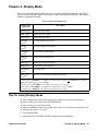
Chapter 4: Display Mode . . . . . . . . . . . . . . . . . . . . . . . . . . . . . . . . . . . . . . . . . . 27
Tips for Using Display Mode . . . . . . . . . . . . . . . . . . . . . . . . . . . . . . . . . . . . . . . . . . . . . . 27
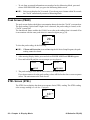
Peak Screen (PEAK). . . . . . . . . . . . . . . . . . . . . . . . . . . . . . . . . . . . . . . . . . . . . . . . . . . . . 28
STEL Screen (STEL) . . . . . . . . . . . . . . . . . . . . . . . . . . . . . . . . . . . . . . . . . . . . . . . . . . . . 28
TWA Screen (TWA) . . . . . . . . . . . . . . . . . . . . . . . . . . . . . . . . . . . . . . . . . . . . . . . . . . . . . 29

4 • 04 Series for CO(-H2)
User ID Screen (USER ID). . . . . . . . . . . . . . . . . . . . . . . . . . . . . . . . . . . . . . . . . . . . . . . . 29
Station ID Screen (STN ID) . . . . . . . . . . . . . . . . . . . . . . . . . . . . . . . . . . . . . . . . . . . . . . . 30
Last Successful Calibration Date (CAL.DATA) . . . . . . . . . . . . . . . . . . . . . . . . . . . . . . . . 30
Last Successful Bump Test Screen (BP.DATA) . . . . . . . . . . . . . . . . . . . . . . . . . . . . . . . . 31
Date/Time Screen (DATE) . . . . . . . . . . . . . . . . . . . . . . . . . . . . . . . . . . . . . . . . . . . . . . . . 31
Temperature Screen (TEMP) . . . . . . . . . . . . . . . . . . . . . . . . . . . . . . . . . . . . . . . . . . . . . . 32
Alarm Points Screen (ALARM--P) . . . . . . . . . . . . . . . . . . . . . . . . . . . . . . . . . . . . . . . . . 32
Adjusting the Buzzer Volume (BUZZ.VOL) . . . . . . . . . . . . . . . . . . . . . . . . . . . . . . . . . . 33
Chapter 5: User Mode and Calibration. . . . . . . . . . . . . . . . . . . . . . . . . . . . . . . 34
Overview. . . . . . . . . . . . . . . . . . . . . . . . . . . . . . . . . . . . . . . . . . . . . . . . . . . . . . . . . . . . . . 34
Entering User Mode . . . . . . . . . . . . . . . . . . . . . . . . . . . . . . . . . . . . . . . . . . . . . . . . . . . . . 37
Tips for Using User Mode . . . . . . . . . . . . . . . . . . . . . . . . . . . . . . . . . . . . . . . . . . . . . . . . 38
Performing a Bump Test (BUMP) . . . . . . . . . . . . . . . . . . . . . . . . . . . . . . . . . . . . . . . . . . 38
Performing a Calibration (GAS CAL) . . . . . . . . . . . . . . . . . . . . . . . . . . . . . . . . . . . . . . . 42
Setting Calibration Parameters (CAL SET) . . . . . . . . . . . . . . . . . . . . . . . . . . . . . . . . . . . 52
Setting Bump Test Parameters (BUMP.SET) . . . . . . . . . . . . . . . . . . . . . . . . . . . . . . . . . . 53
Alarm Settings (ALARM--P) . . . . . . . . . . . . . . . . . . . . . . . . . . . . . . . . . . . . . . . . . . . . . . 57
Updating the Lunch Break Setting (LUNCH) . . . . . . . . . . . . . . . . . . . . . . . . . . . . . . . . . 59
Setting the Confirmation Beep and Non-Compliance Indicator (BEEP) . . . . . . . . . . . . . 59
Updating the Backlight Time (BL TIME). . . . . . . . . . . . . . . . . . . . . . . . . . . . . . . . . . . . . 61
Turning the Key Tone On/Off (KEY.TONE) . . . . . . . . . . . . . . . . . . . . . . . . . . . . . . . . . . 61
Display Mode Items (DISP.SET) . . . . . . . . . . . . . . . . . . . . . . . . . . . . . . . . . . . . . . . . . . . 61
Zero Suppression (ZERO.SUP) . . . . . . . . . . . . . . . . . . . . . . . . . . . . . . . . . . . . . . . . . . . . 62
Zero Follower (ZERO.FLW) . . . . . . . . . . . . . . . . . . . . . . . . . . . . . . . . . . . . . . . . . . . . . . 62
Turning Easy Calibration On/Off (E-CAL) . . . . . . . . . . . . . . . . . . . . . . . . . . . . . . . . . . . 62
Setting the Date/Time (DATE) . . . . . . . . . . . . . . . . . . . . . . . . . . . . . . . . . . . . . . . . . . . . . 63
Turning the Password On/Off (PASS-W) . . . . . . . . . . . . . . . . . . . . . . . . . . . . . . . . . . . . . 63
Viewing the ROM/SUM (ROM/SUM). . . . . . . . . . . . . . . . . . . . . . . . . . . . . . . . . . . . . . . 64
Entering Measuring Mode (START) . . . . . . . . . . . . . . . . . . . . . . . . . . . . . . . . . . . . . . . . 64
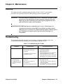
Chapter 6: Maintenance . . . . . . . . . . . . . . . . . . . . . . . . . . . . . . . . . . . . . . . . . . 65
Overview . . . . . . . . . . . . . . . . . . . . . . . . . . . . . . . . . . . . . . . . . . . . . . . . . . . . . . . . . . . . . 65
Troubleshooting . . . . . . . . . . . . . . . . . . . . . . . . . . . . . . . . . . . . . . . . . . . . . . . . . . . . . . . . 65
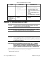
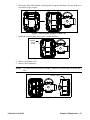
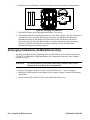
Replacing the Batteries . . . . . . . . . . . . . . . . . . . . . . . . . . . . . . . . . . . . . . . . . . . . . . . . . . 66
Replacing the Charcoal Filter . . . . . . . . . . . . . . . . . . . . . . . . . . . . . . . . . . . . . . . . . . . . . 69
Replacing the Hydrophobic Filter. . . . . . . . . . . . . . . . . . . . . . . . . . . . . . . . . . . . . . . . . . . 71
Replacing the Sensor . . . . . . . . . . . . . . . . . . . . . . . . . . . . . . . . . . . . . . . . . . . . . . . . . . . . 73
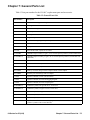
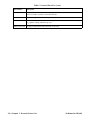
Chapter 7: General Parts List . . . . . . . . . . . . . . . . . . . . . . . . . . . . . . . . . . . . . . 75
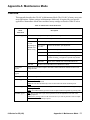
Appendix A: Maintenance Mode . . . . . . . . . . . . . . . . . . . . . . . . . . . . . . . . . . . 77
Overview . . . . . . . . . . . . . . . . . . . . . . . . . . . . . . . . . . . . . . . . . . . . . . . . . . . . . . . . . . . . . 77
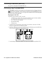
Entering Maintenance Mode . . . . . . . . . . . . . . . . . . . . . . . . . . . . . . . . . . . . . . . . . . . . . . 78
Tips for Using Maintenance Mode . . . . . . . . . . . . . . . . . . . . . . . . . . . . . . . . . . . . . . . . . 79
Performing a Calibration (GAS CAL) . . . . . . . . . . . . . . . . . . . . . . . . . . . . . . . . . . . . . . . 80
Performing a Gas Test (GAS.TEST). . . . . . . . . . . . . . . . . . . . . . . . . . . . . . . . . . . . . . . . . 80
Sensor/Battery Replacement Date (SEN.DATE) . . . . . . . . . . . . . . . . . . . . . . . . . . . . . . . 81

04 Series for CO(-H2) • 5
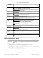
Performing a Bump Test (BUMP) . . . . . . . . . . . . . . . . . . . . . . . . . . . . . . . . . . . . . . . . . . 82
Setting Alarms to Latching or Self-Resetting (LATCH) . . . . . . . . . . . . . . . . . . . . . . . . . 82
Turning the Demand Zero Function On/Off (D.ZERO) . . . . . . . . . . . . . . . . . . . . . . . . . . 82
Turning the Auto Zero Function On/Off (A.ZERO). . . . . . . . . . . . . . . . . . . . . . . . . . . . . 83
Turning the ID Display Function On/Off (ID DISP) . . . . . . . . . . . . . . . . . . . . . . . . . . . . 83
Turning the Zero Suppression On/Off (ZERO.SUP) . . . . . . . . . . . . . . . . . . . . . . . . . . . . 83
Turning the Zero Follower On/Off (ZERO.FLW) . . . . . . . . . . . . . . . . . . . . . . . . . . . . . . 83
User Mode Zero Suppression (ZSUP.DSP) . . . . . . . . . . . . . . . . . . . . . . . . . . . . . . . . . . . 84
User Mode Zero Follower (ZFLW.DSP) . . . . . . . . . . . . . . . . . . . . . . . . . . . . . . . . . . . . . 84
Cylinder Setting (CYL.DISP). . . . . . . . . . . . . . . . . . . . . . . . . . . . . . . . . . . . . . . . . . . . . . 84
Setting the Date/Time (DATE) . . . . . . . . . . . . . . . . . . . . . . . . . . . . . . . . . . . . . . . . . . . . . 84
Turning the Password On/Off (PASS-W) . . . . . . . . . . . . . . . . . . . . . . . . . . . . . . . . . . . . . 85
Viewing the ROM/SUM (ROM/SUM). . . . . . . . . . . . . . . . . . . . . . . . . . . . . . . . . . . . . . . 86
Performing a Default (M.DEF). . . . . . . . . . . . . . . . . . . . . . . . . . . . . . . . . . . . . . . . . . . . . 86
Entering Measuring Mode (START) . . . . . . . . . . . . . . . . . . . . . . . . . . . . . . . . . . . . . . . . 87
Appendix B: Gas Select Mode . . . . . . . . . . . . . . . . . . . . . . . . . . . . . . . . . . . . . . 88
Overview. . . . . . . . . . . . . . . . . . . . . . . . . . . . . . . . . . . . . . . . . . . . . . . . . . . . . . . . . . . . . . 88
Entering Gas Select Mode . . . . . . . . . . . . . . . . . . . . . . . . . . . . . . . . . . . . . . . . . . . . . . . . 88
Tips for Using Gas Select Mode . . . . . . . . . . . . . . . . . . . . . . . . . . . . . . . . . . . . . . . . . . . . 89
Saving the Alarm Points (SAVE-AP) . . . . . . . . . . . . . . . . . . . . . . . . . . . . . . . . . . . . . . . . 89
Turning the Calibration Max Span On/Off (MAX.SPAN) . . . . . . . . . . . . . . . . . . . . . . . . 90
Stealth and Vibrator Settings (STEALTH) . . . . . . . . . . . . . . . . . . . . . . . . . . . . . . . . . . . . 91
Exiting Gas Select Mode (START). . . . . . . . . . . . . . . . . . . . . . . . . . . . . . . . . . . . . . . . . . 91
WARNING: Understand manual before operating. This is an intrinsically safe product.
Substitution of components may impair intrinsic safety. To prevent ignition
of a hazardous atmosphere, batteries must only be changed or charged in
an area known to be nonhazardous. Not tested in oxygen enriched
atmospheres (above 21%).
AVERTISSEMENT:Comprendre le manuel avant de l'utiliser. Ceci est un produit
intrinsèquement sûr. La substitution de composants peut nuire à la sécurité
intrinsèque. Pour éviter l'inflammation d'une atmosphère dangereuse, les
batteries ne doivent être remplacées ou chargées que dans une zone non
dangereuse. Non testé dans des atmosphères enrichies en oxygène (plus de
21%).

6 • Chapter 1: Introduction 04 Series for CO(-H2)
Chapter 1: Introduction
Overview
This chapter briefly describes the CO-04C gas monitor. This chapter also describes the
CO-04C Operator’s Manual (this document). Table 1 at the end of this chapter lists the
specifications for the CO-04C.
About the CO-04C
Using an advanced detection system, the CO-04C personal gas monitor detects the presence
of carbon monoxide (CO). The CO-04C’s compact size and easy-to-use design make it ideally
suited for a wide range of applications, including sewage treatment plants, utility manholes,
tunnels, hazardous waste sites, power stations, petrochemical refineries, mines, paper mills,
drilling rigs, and fire fighting stations. The CO-04C offers a full range of features, including:
• Liquid crystal display (LCD) for complete and understandable information at a glance
• Ultrabright alarm LED
• Distinctive audible/vibrating alarms for dangerous gas conditions and audible alarms for
unit malfunction
• Microprocessor control for reliability, ease of use, and advanced capabilities
• Data logging functions
• Alarm trend data
• STEL, TWA, and over range alarms
• Peak reading
• Built-in time function
• Lunch break feature
• QPS “C/US” classification for Class I, Division I, Groups A, B, C, and D hazardous
atmospheres
WARNING: The Model CO-04C detects elevated levels of carbon monoxide which can
be dangerous or life threatening. When using the CO-04C, you must follow
the instructions and warnings in this manual to assure proper and safe
operation of the unit and to minimize the risk of personal injury. Be sure to
maintain and periodically calibrate the CO-04C as described in this
manual.
AVERTISSEMENT:Le modèle CO-04C détecte les niveaux élevés de monoxyde de carbone
qui peuvent être dangereux ou mettre la vie en danger. Lorsque vous
utilisez le CO-04C, vous devez suivre les instructions et les avertissements
de ce manuel pour assurer un fonctionnement correct et en toute sécurité
de l'appareil et pour réduire les risques de blessures. Assurez-vous de
maintenir et d’étalonner périodiquement le CO-04C comme décrit dans ce
manuel.

04 Series for CO(-H2) Chapter 1: Introduction • 7
Specifications
Table 1: Standard Sensor Specifications/Alarm Points
Table 2: CO-04C Specifications
Detection Range 0 - 500 ppm
Service Range 510 - 2,000 ppm
Reading Increment 0 - 300 ppm: 1 ppm
310 - 2,000 ppm: 10 ppm
Warning Factory Setting 25 ppm
Alarm Factory Setting 50 ppm
Alarm H Factory Setting 1200 ppm
STEL Alarm 200 ppm
TWA Alarm 25 ppm
Sampling
Method
Diffusion
Response Time T90 Within 10 Seconds
Display Graphics LCD Display
Operating
Temperature
& Humidity
Continuous environment: -20°C to 50
°
C/10 to 90% RH
Temporary environment (up to 15 minutes): -40°C to 60
°
C/0 to 95% RH
Indication
Accuracy
Detection Range: ± 5% of reading or ± 5 ppm CO (whichever is greater)
Service Range: ± 20% of reading
Safety/
Regulatory
• ATEX: Certificate Number DEKRA 19ATEX0097
II 1G Ex ia IIC T4 Ga (with alkaline batteries)
II 1G Ex ia IIC T3, Ga (with Ni-MH batteries)
• IECEx: Certificate Number IECEx DEK 19.0059
Ex ia IIC T4 Ga (with alkaline batteries)
Ex ia IIC T3 Ga (with Ni-MH batteries)
• QPS classified, “C/US”, as Intrinsically Safe. Exia. Class I, Groups A, B, C, & D.
Instrument
Power
Information
• Operating Voltage: 3.0V
• Operating Current: 1.0 mA
• Operating Power: 3.0 mW
Power Supply 2 AAA alkaline batteries; 1.5V, 1.175 AH (Duracell MN2400 or PC2400)
OR
2 AAA Ni-MH batteries; 1.2V, 800 mAH (Panasonic Eneloop BK-4MCC)
Continuous
Operating
Hours
@ 25 °C
Alkaline Batteries: 6,200 hours in Measuring Mode (Non Alarm Operation, Fully Charged)
Ni-MH Batteries: 4,200 hours in Measuring Mode (Non Alarm Operation, Fully Charged)

8 • Chapter 1: Introduction 04 Series for CO(-H2)
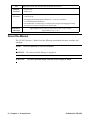
About this Manual
The CO-04C Operator’s Manual uses the following conventions for notes, cautions, and
warnings.
NOTE: Describes additional or critical information.
CAUTION: Describes potential damage to equipment.
WARNING: Describes potential danger that can result in injury or death.
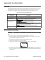
Case High-impact Plastic, RF Shielded, Dust and Weather Proof (IP67)
Standard
Accessories
• Alligator clip
• Rubber boot
Optional
Accessories
• Belt clip
• Calibration cup
• Datalogging and Setup Programs (Windows
®
7, 8, and 10), available at
www.rkiinstruments.com/04series
• IrDA/USB Cable for connecting to a computer when using the Datalogging and Setup
Programs (not needed if computer has an infrared port)
Dimensions
and Weight
Approximately 67(H) x 54(W) x 24(D) mm (2.6”H x 2.1”W x 0.9”D)
Approximately 93 g (3.3 oz.)

04 Series for CO(-H2) Chapter 2: Description • 9
Chapter 2: Description
Overview
This chapter describes the CO-04C instrument and its accessories.
Instrument Description
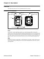
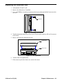
Case
The CO-04C’s sturdy, high-impact plastic case is radio frequency (RF) resistant and is
suitable for use in many environmental conditions, indoors and out. The case is dust proof and
water resistant. A clear plastic window is located on the front of the case for viewing the LCD.
The sensor retainer is located on the right side of the case and allows access to the filters and
sensor. A feature in the lower left corner of the rear case is used to install the optional wrist
strap.
LCD
A digital LCD (liquid crystal display) is visible through a clear plastic window in the top case.
The LCD shows the gas reading. The LCD also shows information for each of the CO-04C’s
operating modes.
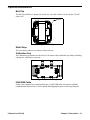
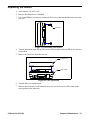
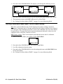
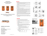
Battery Cover
Battery Cover Screw
IrDA Port
Buzzer Opening
LCD
Wrist Strap
Connection
Control Buttons
CO
AIR
POWER
MODE
Alarm LED
Diffusion Port
Figure 1: Component Location

10 • Chapter 2: Description 04 Series for CO(-H2)
Control Buttons
Two control buttons, AIR and POWER MODE, are located below the LCD.
Alarm LED
The alarm LED above the LCD alert you to gas, low battery, and failure alarms.
Buzzer
One solid-state electronic buzzer is located inside the case. Sound exits the case through a
hole in the upper left corner of the front case. The buzzer sounds for gas alarms, malfunctions,
and low battery voltage. It also provides feedback for button presses and while in Display,
User, Maintenance, or Gas Select Mode.
Vibrator
A vibrating motor inside the CO-04C case vibrates for gas alarms and unit malfunctions.
NOTE: If STEALTH is set to ON, the vibrator only functions when VIB in the STEALTH
Gas Select Mode item is set to ON (see pg.91).
Sensor
The CO sensor is an electrochemical cell that consists of two precious metal electrodes in a
dilute acid electrolyte. A gas permeable membrane covers the sensor face and allows gas to
diffuse into the electrolyte. The gas reacts in the sensor and produces a current proportional to
the concentration of the target gas. The CO-04C’s circuitry amplifies the current, converts the
current to a gas concentration, and displays the concentration on the LCD.
This sensor does not respond to or responds minimally to hydrogen (displays H2 RICH once
H
2
concentration reaches 2000 ppm).
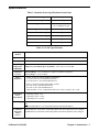
Table 3: CO-04C Control Button Functions
Button Function(s)
AIR • turns on LCD backlight
• resets alarm condition if LATCH is set to ON in Maintenance Mode
• enters User Mode, Maintenance Mode, and Gas Select Mode when used
with POWER MODE
• activates the demand zero function (adjusts the CO-04C’s fresh air reading)
• changes the value of a parameter available for adjustment
• scrolls through parameter options
POWER MODE • turns the CO-04C on and off
• turns on LCD backlight
• enters and scrolls through Display Mode
• enters instructions into the CO-04C’s microprocessor
• resets alarm condition if LATCH is set to ON in Maintenance Mode
• enters User Mode, Maintenance Mode, and Gas Select Mode when used
with AIR

04 Series for CO(-H2) Chapter 2: Description • 11
Filters
Charcoal Filter (Black)
A black charcoal filter is placed into a recess in the sensor gasket over the CO sensor. The
charcoal filter disk scrubs H
2
S and certain hydrocarbons out of the sample to avoid false CO
readings. If false or elevated CO readings are noticed, especially in the presence of H
2
S,
change the charcoal filter.
Hydrophobic Filter
The white, circular hydrophobic filter fits into a recessed area in the front case and is held in
place by the sensor gasket. It prevents water and particulates from entering the instrument.
Infrared Communications Port
An infrared (IR) communications port is located at the top of the instrument, near the LED.
Logged data transmits through the port in standard IrDA protocol. A computer’s infrared port
or an IrDA/USB cable connected to a USB port can be used to download data to the 04 Series
Datalogging Program. See the 04 Series Datalogging Program operator’s manual for data
logging and downloading instructions.
Batteries
2 AAA batteries (alkaline or Ni-MH) power the CO-04C. At 25°C alkaline batteries will last
at least 6,200 hours (258 days) and Ni-MH batteries will last at least 4,200 hours (175 days).
The battery icon in the upper right of the LCD shows remaining battery life.
A low battery warning activates when the CO-04C detects a low battery voltage. The CO-04C
sounds a dead battery alarm when battery voltage is too low for Measuring Mode.
WARNING: Use only Duracell MN2400 or PC2400 or Eneloop BK-4MCC batteries to
maintain the QPS classification of the CO-04C. Use of other batteries will
void the QPS classification and may void the warranty. Do not mix old/new
or different types of batteries.
AVERTISSEMENT:Utiliser uniquement des piles Duracell MN 2400 ou PC 2400 ou
Eneloop BK-4MCC de maintenir la classification QPS de la CO-04C.
L’utilisation d’autres piles annule la classification QPS et peut annuler la
garantie. Ne mélangez pas les anciennes/nouvelles ou différents types de
piles.
WARNING: To prevent ignition of a hazardous atmosphere, the batteries must only be
changed in an area known to be nonhazardous.
AVERTISSEMENT:Pour éviter l'inflammation d'une atmosphère dangereuse, la batterie
ne doit être remplacée que dans une zone non dangereuse.

12 • Chapter 2: Description 04 Series for CO(-H2)
Standard Accessories
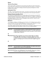
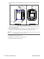
Alligator Clip
An alligator clip installs to 2 spring bars on the rear case. Use the alligator clip to attach the
CO-04C to clothing or a belt. Teeth in the alligator clip’s jaws prevent slipping. The alligator
clip can be rotated to change the instrument’s orientation.
Protective Rubber Boot
A protective rubber boot is installed over the CO-04C.
Open
Alligator Clip
Closed
Figure 2: Alligator Clip
Side Front
Figure 3: Rubber Boot

04 Series for CO(-H2) Chapter 2: Description • 13
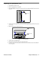
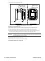
Optional Accessories
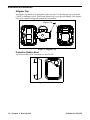
Belt Clip
The belt clip installs to 2 spring bars on the rear case and is used to easily clip the CO-04C
onto a belt.
Wrist Strap
The wrist strap connects to a feature on the back case.
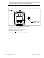
Calibration Cup
The calibration cup installs over the sensor. You must use the calibration cup when performing
a bump test, calibration, or gas test.
IrDA/USB Cable
Unless your computer has a built-in IrDA port, a IrDA/USB cable is needed to establish
communication between the CO-04C and the Datalogging Program or the Setup Program.
Belt Clip
Figure 4: Belt Clip
Figure 5: Calibration Cup

14 • Chapter 3: Measuring Mode 04 Series for CO(-H2)
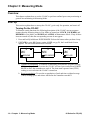
Chapter 3: Measuring Mode
Overview
This chapter explains how to use the CO-04C to perform confined space entry monitoring or
general area monitoring in Measuring Mode.
Start Up
This section explains how to start up the CO-04C, get it ready for operation, and turn it off.
Turning On the CO-04C
To illustrate certain functions, the following description of the CO-04C start up sequence
assumes that the following items in User Mode are turned on: LUNCH, CAL.RMDR, and
BP.RMDR in User Mode, and ID DISP and A.ZERO in Maintenance Mode. If any of these
items are turned off, then the corresponding screens do not appear.
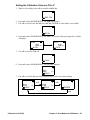
1. Press and briefly hold down POWER MODE. Release the button when you hear a beep.
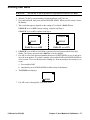
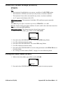
2. If LUNCH is set to ON (factory setting if OFF, see pg.59), the Lunch Break Screen
appears. The unit counts down from 5 seconds.
a. Continue Accumulating: To continue accumulating peak and time-weighted average
(TWA) readings from the last time the CO-04C was used, press and release POWER
MODE or allow the countdown to reach 0. The short-term exposure limit (STEL)
reading is reset each time the CO-04C is turned on.
b. Reset Accumulation: To reset the accumulation of peak and time-weighted average
(TWA) readings, press and release AIR before the countdown reaches 0.
5
SEC
RESUME
5
SEC
YES .MODE
5
SEC
NO .AIR

04 Series for CO(-H2) Chapter 3: Measuring Mode • 15
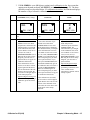
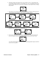
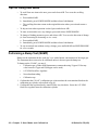
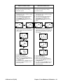
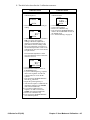
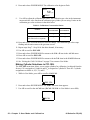
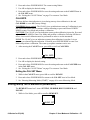
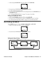
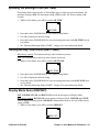
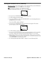
3. If CAL.RMDR is set to ON (factory setting) and a calibration is due, the screen that
appears next depends on how CAL.EXPD is set in User Mode (see pg.53). The three
possible screens are described below. If a calibration is not due, the instrument displays
the number of days left until a calibration is due.
CAL.EXPD set to
CONFIRM (factory setting)
CAL.EXPD set to
CANT.USE
CAL.EXPD set to
NONE
LCD
Sound Buzzer sounds double pulsing
tone
Buzzer sounds double pulsing
tone
None
Action • Option A, Perform calibration
:
Press and release POWER
MODE to enter User Mode
and perform a calibration. The
instrument takes you straight
to the calibration start screen
in User Mode’s GAS CAL\A-
CAL(E-CAL) item (if
Password Protection is set to
On using the 04 Series Setup
Program, you must enter a
password first). See pg.42 for
calibration instructions.
If the calibration is success-
ful, the screen above will not
appear again until the unit is
due for calibration. If the cali-
bration is not successful, the
screen above will again appear
in the startup sequence.
• Option B, Bypass message
: To
continue without performing a
calibration, press and release
AIR.
The CO-04C cannot be used until
a successful calibration is per-
formed. Press and release
POWER MODE to enter User
Mode and perform a calibration.
The instrument takes you straight
to the calibration start screen in
User Mode’s GAS CAL/A-CAL
(E-CAL) item (if Password Pro-
tection is set to On using the 04
Series Setup Program, you must
enter a password first). If you
don’t press POWER MODE, the
instrument automatically goes to
the calibration start screen after 6
seconds (if Password Protec-
tion is set to On using the 04
Series Setup Program, you must
enter a password first). See pg.42
for calibration instructions.
If the calibration is successful,
the screen above will not appear
again until the unit is due for cali-
bration. If the calibration is not
successful, the screen above will
again appear in the startup
sequence.
• Option A, Perform calibration
:
If you want to enter User
Mode and perform a
calibration, press and release
POWER MODE. The
instrument takes you straight
to the calibration start screen
in User Mode’s GAS CAL/A-
CAL (E-CAL) item (if
Password Protection is set to
On using the 04 Series Setup
Program, you must enter a
password first).
• Option B, Bypass message
:
To continue without
performing a calibration, wait
a few seconds for the
instrument to continue with its
startup sequence.
CAL
CAL - LMT
FAIL
CAL - LMT
0
d
NEXT .CAL

16 • Chapter 3: Measuring Mode 04 Series for CO(-H2)
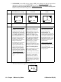
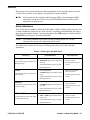
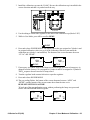
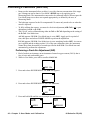
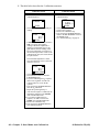
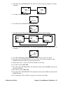
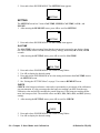
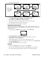
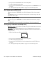
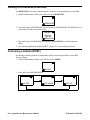
4. If BP.RMDR is set to ON (factory setting is OFF) and a bump test is due, the screen that
appears next depends on how BP.EXPD is set in User Mode (see pg.56). The three
possible screens are described below. If a bump test is not due, the instrument displays the
number of days left until a bump test is due.
5. The Date/Time Screen appears for a few seconds.
BP.EXPD set to
CONFIRM (factory setting)
BP.EXPD set to
CANT.USE
BP.EXPD set to
NONE
LCD
Sound Buzzer sounds double pulsing
tone
Buzzer sounds double pulsing
tone
None
Action • Option A, Perform bump test
:
Press and release POWER
MODE to enter User Mode
and perform a bump test. The
instrument takes you straight
to the bump test start screen in
User Mode’s BUMP item (if
Password Protection is set to
On using the 04 Series Setup
Program, you must enter a
password first). See pg.38 for
bump test instructions.
If the bump test is successful,
the screen above will not
appear again until the unit is
due for bump testing. If the
bump test is not successful,
the screen above will again
appear in the startup sequence.
• Option B, Bypass message
: To
continue without performing a
bump test, press and release
AIR.
The CO-04C cannot be used
until a successful bump test is
performed. Press and release
POWER MODE to enter User
Mode and perform a bump test.
The instrument takes you
straight to the bump test start
screen in User Mode’s BUMP
item (if Password Protection is
set to On using the 04 Series
Setup Program, you must enter a
password first). If you don’t
press POWER MODE, the
instrument automatically goes to
the bump test start screen after 6
seconds (if Password Protec-
tion is set to On using the 04
Series Setup Program, you must
enter a password first). See
pg.38 for bump test instructions.
If the bump test is successful, the
screen above will not appear
again until the unit is due for
bump testing. If the bump test is
not successful, the screen above
will again appear in the startup
sequence.
• Option A, Perform bump test
:
If you want to enter User
Mode and perform a bump
test, press and release
POWER MODE. The
instrument takes you straight
to the bump test start screen in
User Mode’s BUMP item (if
Password Protection is set to
On using the 04 Series Setup
Program, you must enter a
password first).
• Option B, Bypass message
:
To continue without
performing a bump test, wait
a few seconds for the
instrument to continue with its
startup sequence.
CAL
BP - LMT
FAIL
BP - LMT
0
d
NEXT .BP
2020
4.21
10:40

04 Series for CO(-H2) Chapter 3: Measuring Mode • 17
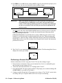
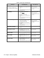
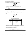
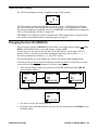
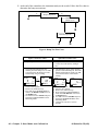
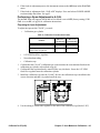
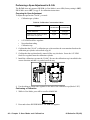
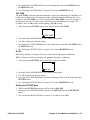
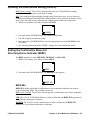
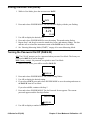
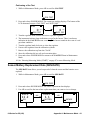
6. The Battery Voltage Screen appears for a few seconds. An “AL-L” at the bottom of the
screen indicates that the alarms are set to latching. An “AL-A” at the bottom of the screen
indicates that the alarms are set to auto reset. See pg.82 for a description of how to change
this parameter.
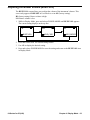
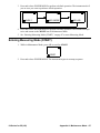
7. The following screens display for 1 second each: Gas Name, Full Scale, Warning Setpoint,
Alarm Setpoint, Alarm H Setpoint, STEL Setpoint, and TWA Setpoint.
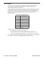
8. If ID DISP is set to ON (factory setting is OFF, see pg.83), the User ID Screen appears
for a few seconds, followed by the Station ID Screen.
9. If the CO-04C experiences a sensor failure during start up, a screen indicating that the
sensor failed appears and the buzzer sounds a double pulsing tone once per second.
You cannot acknowledge the failure and continue to Measuring Mode. Replace the failed
sensor as soon as possible.
batt
2.8
AL -L
v
CO
2000
F . S .
ppm
CO
25
WARNING
ppm
CO
ppm
CO
50
ALARM
ppm
CO
1200
ALARM H
ppm
CO
200
STEL
ppm
CO
25
TWA
ppm
USER
ID
U_ID_001
STN
ID
S_ID_001
CO
FAIL
SENSOR
ppm

18 • Chapter 3: Measuring Mode 04 Series for CO(-H2)
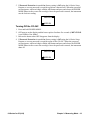
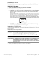
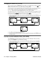
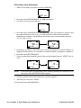
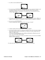
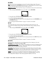
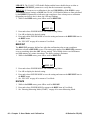
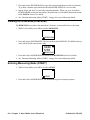
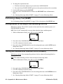
10. If A.ZERO is set to ON (factory setting is OFF, see pg.83), the instrument prompts you to
do an auto zero. An auto zero operation sets the reading to 0 ppm.
WARNING: Make sure that the instrument is in a known fresh air environment (an
environment free of combustible or toxic gases and of normal oxygen
content, 20.9%) before performing an auto zero operation. If you perform
an auto zero operation in an area with gases present, the adjustment will
not be accurate.
You must press and release the POWER MODE button to perform an auto zero function.
If you do not press any key, after 15 seconds, the instrument enters Measuring Mode
without performing an auto zero.
If Password Protection is turned On (factory setting is Off) using the 04 Series Setup
Program, a user-set password is required to perform an auto zero. When the password
screen appears, adjust each digit with the AIR button and press and release the POWER
MODE button to move on to the next digit. Once the password is entered, the instrument
performs the auto zero.
11. The CO-04C is now monitoring for gas in Measuring Mode. The Measuring Mode Screen
displays the current gas reading.
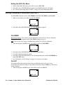
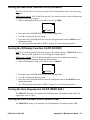
Performing a Demand Zero
Perform a demand zero before using the CO-04C. This sets the reading to 0 ppm.
1. Find a fresh-air environment. This is an environment free of toxic or combustible gases
and of normal oxygen content (20.9%).
2. Turn on the unit as described above in “Turning On the CO-04C”.
3. Press and hold AIR. The buzzer pulses and the LCD prompts you to continue holding AIR
(if KEY.TONE is set to ON in User Mode).
4. Continue to hold AIR until the LCD prompts you to release it. The CO-04C sets the fresh
air reading. Start up is complete and the unit is now ready for monitoring.
A .ZERO
YES .MODE
NO .AIR
0000
PASS-W
CO
0
ppm

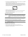
04 Series for CO(-H2) Chapter 3: Measuring Mode • 19
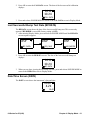
5. If Password Protection is turned On (factory setting is Off) using the 04 Series Setup
Program, a user-set password is required to perform a demand zero. When the password
screen appears, adjust each digit with the AIR button and press and release the POWER
MODE button to move on to the next digit. Once the password is entered, the instrument
sets the fresh air reading.
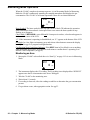
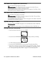
Turning Off the CO-04C
1. Press and hold POWER MODE.
2. OFF appears on the display and the buzzer pulses for about five seconds (if KEY.TONE
is set to ON in User Mode).
3. Release the button when OFF disappears from the display.
4. If Password Protection is turned On (factory setting is Off) using the 04 Series Setup
Program, a user-set password is required to turn off the CO-04C. When the password
screen appears, adjust each digit with the AIR button and press and release the POWER
MODE button to move on to the next digit. Once the password is entered, the instrument
shuts off.
0000
PASS-W
0000
PASS-W

20 • Chapter 3: Measuring Mode 04 Series for CO(-H2)
Measuring Mode Operation
When the CO-04C completes its startup sequence, it is in Measuring Mode. In Measuring
Mode the CO-04C continuously monitors the sampled atmosphere and displays the gas
concentration. The CO-04C is in Normal Operation if there are no alarm indications.
Heart Symbol: The heart symbol in the top right corner of the LCD indicates the operation
status and flashes when normal. A microprocessor error causes the heart symbol to stop
flashing or to disappear.
Check Mark: If BP.RMDR is set to ON and if a bump test is not due, a check mark appears in
the lower left corner of the LCD.
“S”
: If the instrument is operating in Stealth Mode, an “S.” appears at the bottom of the LCD.
Backlight: In a low-light environment, press and release either button to turn on the display
backlight. See pg.61 to program backlight duration.
Confirmation/Non-Compliance Indicator
: If the BEEP item in User Mode is set to anything
other than OFF, the CO-04C gives periodic indications to confirm that it’s operating or to
indicate a non-compliance (see pg.59).
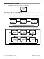
Monitoring an Area
1. Start up the CO-04C as described above in “Start Up” on page 14. It is now in Measuring
Mode.
2. The instrument displays the CO reading. The H
2
reading is not displayed but “H2 RICH”
appears once the H
2
concentration rises above 2000 ppm.
3. Take the CO-04C to the monitoring area.
4. Wait at least 15 seconds.
5. If a reading is observed, allow the reading to stabilize to determine the gas concentration
present.
6. If a gas alarm occurs, take appropriate action. See pg.23.
CO
0
S.
ppm
CO
0
ppm
Page is loading ...
Page is loading ...
Page is loading ...
Page is loading ...
Page is loading ...
Page is loading ...
Page is loading ...
Page is loading ...
Page is loading ...
Page is loading ...
Page is loading ...
Page is loading ...
Page is loading ...
Page is loading ...
Page is loading ...
Page is loading ...
Page is loading ...
Page is loading ...
Page is loading ...
Page is loading ...
Page is loading ...
Page is loading ...
Page is loading ...
Page is loading ...
Page is loading ...
Page is loading ...
Page is loading ...
Page is loading ...
Page is loading ...
Page is loading ...
Page is loading ...
Page is loading ...
Page is loading ...
Page is loading ...
Page is loading ...
Page is loading ...
Page is loading ...
Page is loading ...
Page is loading ...
Page is loading ...
Page is loading ...
Page is loading ...
Page is loading ...
Page is loading ...
Page is loading ...
Page is loading ...
Page is loading ...
Page is loading ...
Page is loading ...
Page is loading ...
Page is loading ...
Page is loading ...
Page is loading ...
Page is loading ...
Page is loading ...
Page is loading ...
Page is loading ...
Page is loading ...
Page is loading ...
Page is loading ...
Page is loading ...
Page is loading ...
Page is loading ...
Page is loading ...
Page is loading ...
Page is loading ...
Page is loading ...
Page is loading ...
Page is loading ...
Page is loading ...
Page is loading ...
Page is loading ...
-
 1
1
-
 2
2
-
 3
3
-
 4
4
-
 5
5
-
 6
6
-
 7
7
-
 8
8
-
 9
9
-
 10
10
-
 11
11
-
 12
12
-
 13
13
-
 14
14
-
 15
15
-
 16
16
-
 17
17
-
 18
18
-
 19
19
-
 20
20
-
 21
21
-
 22
22
-
 23
23
-
 24
24
-
 25
25
-
 26
26
-
 27
27
-
 28
28
-
 29
29
-
 30
30
-
 31
31
-
 32
32
-
 33
33
-
 34
34
-
 35
35
-
 36
36
-
 37
37
-
 38
38
-
 39
39
-
 40
40
-
 41
41
-
 42
42
-
 43
43
-
 44
44
-
 45
45
-
 46
46
-
 47
47
-
 48
48
-
 49
49
-
 50
50
-
 51
51
-
 52
52
-
 53
53
-
 54
54
-
 55
55
-
 56
56
-
 57
57
-
 58
58
-
 59
59
-
 60
60
-
 61
61
-
 62
62
-
 63
63
-
 64
64
-
 65
65
-
 66
66
-
 67
67
-
 68
68
-
 69
69
-
 70
70
-
 71
71
-
 72
72
-
 73
73
-
 74
74
-
 75
75
-
 76
76
-
 77
77
-
 78
78
-
 79
79
-
 80
80
-
 81
81
-
 82
82
-
 83
83
-
 84
84
-
 85
85
-
 86
86
-
 87
87
-
 88
88
-
 89
89
-
 90
90
-
 91
91
-
 92
92


RKI Instruments 04 Series CO Owner's manual
- Type
- Owner's manual
- This manual is also suitable for
Ask a question and I''ll find the answer in the document
Finding information in a document is now easier with AI
Related papers
-
RKI Instruments 01-Series Reference guide
-
-
-
RKI Instruments SC-8000 User manual
-
-
-
-
-
-
Other documents
-
AIR SYSTEMS INTERNATIONAL CO-91 Series User manual
-
 Macurco PM100 Quick start guide
-
 Unipro 17-01-004 UniTire User manual
-
RKI GX-3R Pro Five Gas Personal Bluetooth Monitor User manual
-
Altair ALTAIR PRO Operating instructions
-
Sonic Alert SBP100 User manual
-
-
 Industrial Scientific IS-CAL Owner's manual
-
 Scott Safety Proton ZM User manual
-
Sanyo NC-MDU01 User manual


