HeatPro HeatPro VS HP50951T User manual
- Category
- Above ground pool accessories
- Type
- User manual
This manual is also suitable for

USE ONLY GENUINE REPLACEMENT PARTS 1
51300002101 RevA
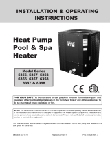
IN GROUND POOL/SPA HEAT PUMP HEATERS
INSTALLATION & OPERATIONS MANUAL
FOR YOUR SAFETY
This Heat Pump is listed by ETL as complying
with the latest edition of the UL Standard for
Safety for Heating and Cooling Equipmen t”,
UL60335 and CSA C22.2 No.60335-1and
All Heat Pumps must be installed in accordance
with all applicable National and Local codes. In
the absence of local codes, refer to the latest
edition of the National Electric Code (NEC) in th
e
United States and the Canadian Electric Code
(CEC) in Canada.
FOR YOUR SAFETY:
This product must be installed and serviced by
authoriz
ed personnel, qualified in pool/spa heate
r
installation. Improper installation and/or
operation can cause death, serious injury
and/or property damage.
SAVE THESE INSTRUCTIONS
CONTENTS
Pg.
GETTING STARTED 2
INSTALLATION 8
LOCATING THE HEATER 8
WATER PIPING 10
ELECTRICAL CONNECTIONS 13
CHECK-OUT & START-UP 14
CONTROL SETUP 14
MAINTENANCE & SERVICE 16
WATER CHEMISTRY 16
WINTERIZATION 17
COMPONENT SERVICE 17
TROUBLESHOOTING 17
PARTS 21
60335-2-40.

2 USEONLYGENUINEREPLACEMENTPARTS
51300002101RevA
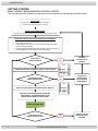
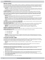
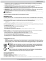
GETTING STARTED
WHAT TO EXPECT WHEN OPERATING YOUR POOL HEATER
This flow chart provides guidance to protect pool users and product by maintaining good water quality.
INSTALLATION
Verifythatproductinstallationwasperformed
tolocalcodesandaccordingtothismanual.
ISPOOL/SPAIN
CHEMICALBALANCE?
INITIALUSEORSPRINGSTARTUP
Checkallpool/spawaterpiping.Donotconnectproducttowaterpiping.
BYPASSTOCLOSEDPOSITION,WATERDIRECTEDTOPRODUCT
TURNONELECTRICPOWERANDGASASREQUIRED.
STARTPRODUCT.PROGRAMREQUIREDWATER
TEMPERATUREONPRODUCTCONTROLPANEL.
IMPORTANTFORPOOLUSERHEALTHANDPRODUCTPERFORMANCE
Verify Chlorine or Bromine level every 2-3 days
Verify PH level every week
Verify Alkalinity level every 3-4 weeks (2 weeks if using an Automatic
Chlorine or Bromine Feeder)
Verify Water Hardness and Total Dissolved Solids (TDS) every month (it is
recommended that a pool professional perform this testing)
ISHEATING/COOLING
NEEDEDWITHIN1WEEK?
SETBYPASSTO
OPENPOSITION,
WATERDIVERTED
FROMPRODUCT
CONNECTWATERPIPINGTOPRODUCT,BYPASSTOOPEN POSITION
ISHEATING/COOLING
NEEDEDFORRESTOFYEAR?
DISCONNECT
WATERPIPINGTO
PRODUCT
TURNOFFELECTRIC
POWERANDGASAS
REQUIRED
ENJOYYOURPOOL/SPA
NO
NO
NO
OPEN
PRODUCT
POOL/SPA
CLOSED
PRODUCT
POOL/SPA

USEONLYGENUINEREPLACEMENTPARTS 3
51300002101RevA
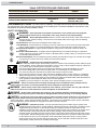
PLEASE READ BEFORE PROCEEDING
See product rating plate for manufactures information.
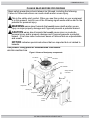
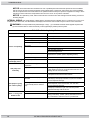
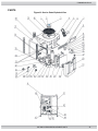
HEATER CONSTRUCTION
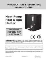
Figure1: Names of heat pump components
Basic safety precautions should always be followed, including the following:
Failure to follow instructions can cause death and/or severe injury.
This is the safety-alert symbol. When you see this symbol on your equipment
or in this manual, look for one of the following signal words and be alert to the
potential for personal injury.
WARNING
warns about hazards that could cause death and/or severe
injury or major property damage and if ignored presents a potential hazard.
CAUTION
warns about hazards that could cause minor or moderate
personal injury and/or property damage and if ignored presents a potential
hazard. It can also make consumers aware of actions that are unpredictable
and unsafe.
NOTICE
indicates special instructions that are important but not related to
hazards.
To
p
Panel
Fan Guard
Eva
p
orato
r
Fan
F
a
n M
otor
Condense
r
Compressor
Bonding lug
Control Box
Front Panel
Service Panel
Control
Board
User Interface
Safety Switches
& Controls

4 USE ONLY GENUINE REPLACEMENT PARTS
51300002101 RevA
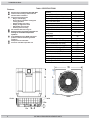
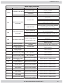
Table1: SPECIFICATIONS
Features:
R410A Inverter Compressor with Soft Start
Titanium heat exchanger withstands the
harshest water conditions
Touch Screen Control with
o Easy to read display;
o Auto mode for automatic heating and
cooling operation
o Remote enable connection
o Display of diagnostic codes
o Data backup and recovery
o Auxiliary timer and relay
UV resistant cabinet for long life
Defrost function to manage evaporator coil
frosting for low ambient temperature
operation
High (580PSI) and low (44PSI) refrigerant
pressure switche
s monitoring extreme
operation
Compressor sound blanket
Corrosion resistant evaporator fins
Models
HP50951T
06/1/032-802 zH/esahP/egatloV
Capacity (btu/h) 80A-80RH-80W 27,200~96,900
Power Input, KW (80A-80RH-80W) 0.70~5.36
COP 80A-80RH-80W 12.5~5.3
Capacity (btu/h) 80A-63RH-80W
26,280~92600
COP 80A-63RH-80W
12.2~5.1
Capacity (btu/h) 50A-63RH-80W
11,485~59730
COP 50A-63RH-80W
8.2~4.1
Compressor/Fan Motor/System
RLA (amp)
29/1.7/30.7
Compressor/Fan Motor/System
LRA (amp)
80
Min. Circuit Ampacity (amp) 43
Recommended Breaker Size (amp) 60
Max Fuse Breaker Size (amp) 60
Recommended water flow (gpm)
42
Minimum water flow (gpm)
37
Maximum water flow (gpm)
56
Water Connector (dia. in) 2” TriStar
Unit size L x W x H (in)
33.8x36.2x44.2
Weight (lbs) 251
Shipping Weight (lbs) 380
Shipping size L x W x H (in)
39.2x42.3x48
Outlet
6in
Intlet
3.5in
H
L
W

USEONLYGENUINEREPLACEMENTPARTS 5
51300002101RevA
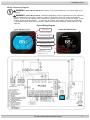
Wiring Connection Diagram
WARNING
– Risk of Electric Shock Before working on any electrical equipment, turn off power supply to the
equipment.
WARNING
– Risk of Electric Shock. All electrical wiring MUST conform to applicable local codes, regulations,
and the National Electric Code (NEC). Hazardous voltage can cause death, shock, burn, and/or serious property
damage. To reduce the risk of electric shock, do NOT use an extension cord to connect unit to electric supply. Provide
a properly located electrical receptacle. To reduce the risk of electric shock replace damaged wiring immediately.
Locate conduit to prevent abuse from lawn mowers, hedge trimmers and other equipment. Do NOT ground to a gas
supply line.
Figure2 Wiring Diagram
SystemON(BlueScreen)
Currentinletwatertemperature
Currentoutletwatertemperature
Targettemperaturesetting
Systemtime:hours:minutes
CircularTouchButton:
Pressfor0.5sforsystemONandOFF.
Pressfor5stolockthescreen.
Currentpageposition
ModeandActivity
SystemOFF(BlackScreen)

6 USE ONLY GENUINE REPLACEMENT PARTS
51300002101 RevA
Table2: CERTIFICATION AND COMPLIANCE
CERTIFICATION CODES AND STANDARDS CANADA
DESIGN CERTIFIED ETL/ITS
DESIGN COMPLIANT C22.2 No.60335-1 and 60335-2-40
INSTALLATION COMPLIANT ELECTRIC
CSA C22.1 – Canadian
Electrical Code, Part I
USA
ETL/ITS
UL60335-1 and UL 60335-2-40
ANSI/NFPA 70
CONFORMANCE WITH CODES: The heater shall be installed in accordance with all local and state codes and with
the requirements of the authority having jurisdiction of the installing site. The heater installation must conform to the
latest edition of the above listed installation codes.
SAFETY INFORMATION
WARNING
– Read, Understand, and Follow all Instructions in this manual and on the equipment.
Failure to follow instructions can cause death, severe injury and/or serious property damage.
WARNING
– Suction Entrapment Hazard. Suction in suction outlets and/or suction outlet covers which are,
damaged, broken, cracked, missing, or unsecured can cause death and/or severe injury due to the following
entrapment hazards:
Hair Entrapment- Hair can become entangled in suction outlet cover.
Limb Entrapment- A limb inserted into an opening of a suction outlet sump or suction outlet cover that is damaged,
broken, cracked, missing, or not securely attached can result in a mechanical bind or swelling of the limb.
Body Suction Entrapment- A negative pressure applied to a large portion of the body or limbs can result in an
entrapment.
Evisceration/ Disembowelment - A negative pressu
re applied directly to the intestines through an u
nprotected
suction outlet sump or suction outlet cover which is, damaged, broken, cracked, missing, or unsecured can result
in evisceration/ disembowelment.
Mechanical Entrapment- There is potential for jewelry, swimsuit, hair decorations, finger, toe or knuckle to be caught
in an opening of a suction outlet cover resulting in mechanical entrapment.
WARNING
- To Reduce the risk of Entrapment Hazards:
o When outlets are small enough to be blocked by a person, a minimum of two functioning suction outlets per pump
must be installed. Suction outlets in the same plane (i.e. floor or wall), must be installed a minimum of three feet
(3’) [1 meter] apart, as measured from near point to near point.
o Dual suction fittings shall be placed in such locations and distances to avoid “dual blockage” by a user.
o Dual suction fittings shall not be located on seating areas or on the backrest for such seating areas.
o The maximum system flow rate shall not exceed the flow rating of as listed on Table 1.
o Never use Pool or Spa if any suction outlet component is damaged, broken,
cracked, missing, or not attached.
o Replace damaged, broken, cracked, missing, or not securely attached suction outlet components immediately.
o In addition two or more suction outlets per pump installed in accordance with latest ASME, APSP Standards and
CPSC guidelines, follow all National, State, and Local codes applicable.
o Installation of a vacuum release or vent system, which relieves entrapping suction, is recommended.
WARNING
– Failure to remove pressure test plugs and/or plugs used in winterization of the pool/spa from the
suction outlets can result in an increase potential for suction entrapment as described above.
WARNING
– Failure to keep suction outlet components clear of debris, such as leaves, dirt, hair, paper and other
material can result in an increase potential for suction entrapment as described above.
WARNING
– Suction outlet components have a finite life, the cover/grate should be inspected frequently and
replaced at least every seven years or if found to be damaged, broken, cracked, missing, or not securely attached.
CAUTION
– Components such as the filtration system, pumps and heater must be positioned so as to prevent their
being used as means of access to the pool by young children. To reduce risk of injury, do not permit children to use or
climb on this product. Closely supervise children at all times. Components such as the filtration system, pumps, and heaters
must be positioned to prevent children from using them as a means of access to the pool.
WARNING
– Hazardous Pressure. Pool and spa water heating and circulation systems operate under
hazardous pressure during start up, normal operation, and after pump shut off. Stand clear of circulation system
equipment during pump start up. Failure to follow safety and operation instructions could result in violent
separation of the pump housing and cover, and/or filter housing and clamp due to pressure in the system, which
could cause death, severe personal injury and/or property damage, Before servicing pool and spa water
circulation system, all system and pump controls must be in off position and filter manual air relief valve must be
in open
position. Before starting system pump, all system valves must be set in a position to allow system water
to return back to the pool. Do not change filter control valve position while system pump is running. Before
starting system pump, fully open filter manual air relief valve. Do not close filter manual air relief valve until a
steady stream of water (not air or air and water) is discharged.
NEC

USEONLYGENUINEREPLACEMENTPARTS 7
51300002101RevA
WARNING
– Separation Hazard. Failure to follow safety and operation instructions could result in violent
separation of pump and/or filter components. Strainer cover must be properly secured to pump housing with
strainer cover lock ring. Before servicing pool and spa circulation system, filters manual air relief valve must be in
open position. Do not operate pool and spa circulation system if a system component is not assembled properly,
damaged, or missing. Do not operate pool and spa circulation system unless filter manual air relief valve body is
in locked position in filter upper body. Never operate or test the circulation system at more than 50 PSI. Do
not purge the system with compressed air. Purging the system with compressed air can cause components to
explode, with risk of severe injury or death to anyone nearby. Use only a low pressure (below 5 PSI), high
volume blower when air purging the pump, filter, or piping.
WARNING
– Risk of Electric Shock. All electrical wiring MUST be in conformance with applicable local
codes, regulations, and the National Electric Code (NEC). Hazardous voltage can shock, burn, and cause death
or serious property damage. To reduce the risk of electric shock, do NOT use an extension cord to connect unit
to electric supply. Provide a properly located electrical receptacle. Before working on any electrical equipment,
turn off power supply to the equipment. To reduce the risk of electric shock replace damaged wiring immediately.
Locate conduit to prevent abuse from lawn mowers, hedge trimmers and other equipment. Do NOT ground to a
gas supply line.
WARNING
– Risk of Electric Shock.
Failure to ground all electrical equipment can cause serious or fatal electrical shock
hazard. Electrical ground all electrical equipment before connecting to electrical power supply.
WARNING
– Risk of Electric Shock. Failure to bond all electrical equipment to pool structure will increase risk for
electrocution and could result in injury or death. To reduce the risk of electric shock, see installation instructions and consult a
professional electrician on how to bond all electrical equipment. Also, contact a licensed electrician for information on local
electrical codes for bonding requirements.
Notes to electrician: Use a solid copper conductor, size 8 or larger. Run a continuous wire from external bonding lug to
reinforcing rod or mesh. Connect a No. 8 AWG (8.4 mm
2
) [No. 6 AWG (13.3 mm
2
) for Canada] solid copper bonding wire to the
pressure wire connector provided on the electrical equipment and to all metal parts of swimming pool, spa, or hot tub, and metal
piping (except gas piping), and conduit within 5 ft. (1.5 m) of inside walls of swimming pool, spa, or hot tub.
IMPORTANT - Reference NEC codes for all wiring standards including, but not limited to, grounding, bonding and other general
wiring procedures.
CAUTION – These heaters are intended for use with permanently-installed pools and may be used with hot tubs and spas if
so marked. Do not use with storable pools. A permanently-installed pool is constructed in or on the ground or in a building
such that it cannot be readily disassembled for storage. A storable pool is constructed so that it is capable of being readily
disassembled for storage and reassembled to its original integrity.
WARNING
– Risk of Hyperthermia. To avoid hyperthermia the following “Safety Rules for Hot Tubs” are recommended by
the U.S. Consumer Product Safety Commission.
1. Spa or hot tub water temperatures should never exceed 104°F [40°C]. A temperature of 100°F [38°C] is considered
safe for a healthy adult. Special caution is suggested for young children. Prolonged immersion in hot water can
induce hyperthermia.
2. Drinking of alcoholic beverages before or during spa or hot tub use can cause drowsiness, which could lead to
unconsciousness and subsequently result in drowning.
3. Pregnant women beware! Soaking in water above 100°F [38°C] can cause fetal damage during the first three
months of pregnancy (resulting in the birth of a brain-damaged or deformed child). Pregnant women should adhere to
the 100°F [38°C] maximum rule.
4. Before entering the spa or hot tub, users should check the water temperature with an accurate thermometer; spa or
hot tub thermostats may err in regulating water temperatures by as much as 4°F (2.2°C).
5. Persons taking medications, which induce drowsiness, such as tranquilizers, antihistamines or anticoagulants, should
not use spas or hot tubs.
6. If the pool/spa is used for therapy, it should be done with the advice of a physician. Always stir pool/ spa water before
entering the pool/spa to mix in any hot surface layer of water that might exceed healthful temperature limits and cause
injury. Do not tamper with controls, because scalding can result if safety controls are not in proper working order.
7. Persons with a medical history of heart disease, circulatory problems, diabetes or blood pressure problems should
obtain a physician’s advice before using spas or hot tubs.
8. Hyperthermia occurs when the internal temperature of the body reaches a level several degrees above normal body
temperature of 98.6°F [37°C]. The symptoms of Hyperthermia include: drowsiness, lethargy, dizziness, fainting,
and an increase in the internal temperature of the body.
The effects of Hyperthermia include:
Unawareness of impending danger.
Failure to perceive heat.
Failure to recognize the need to leave the spa.
Physical inability to exit the spa.
Fetal damage in pregnant women.
Unconsciousness resulting in danger of drowning.

8 USEONLYGENUINEREPLACEMENTPARTS
51300002101RevA
INSTALLATION
This manual contains instructions for installation, operation, maintenance, troubleshooting, and parts lists for the proper operation of
the swimming pool heaters. Manufacturer strongly recommends that the installer read the manual before installing the swimming
pool heater. If after reviewing the manual any questions remain unanswered, contact the factory or local representative. Following
heater installation, the installer should leave all manuals with the consumer for future reference.
NOTICE: The installation instructions are intended for the use of a qualified technician, specifically trained and experienced in
the installation of this type of heating equipment. Some states or provinces require that installer be licensed. If this is the case in
the state or province where heater is located, the contractor must be properly certified.
SPRINKLER HEADS: The heater is designed to handle the wettest weather conditions that are typical of rain and high
humidity. Sprinkler heads force high-pressure water into the unit from the side at an odd angle. Make sure there are no sprinkler
heads near the heater that will spray on or into the unit. Many sprinkler systems are connected to a well system, whose water is
high in minerals, Sulphur, salt and other aggressive contaminates, that will leave a buildup on the unit and electronics causing
corrosion and shortens life.
NOTICE: Damage from sprinkler interaction is not covered under the warranty agreement. Make sure that sprinklers are
placed at a sufficient distance away so that normal wind will not carry the mist to the heat pump.
NOTICE:
If located in an oceanfront area, the heat pump should be placed out of direct spray of sand and salt. This will clog,
damage, and corrode the unit. You may also consider protecting the unit by creating a physical barrier outside of the minimum
clearances between the unit and the prevailing beachfront wind. Damage caused by sand or salt spray is not covered by the
warranty.
THE USE OF A POOL COVER IS RECOMMENDED
. A pool cover reduces heat loss, conserves chemicals, lowers the
load on filter systems and may provide a valuable safety feature
EQUIPMENT INSPECTION:
On receipt of the heater, inspect the heater carton(s) for damage. If any carton(s) is damaged,
note it when signing for it. Remove the heater from the carton(s) inspect it and advise the carrier of any damages at once.
NOTICE:
Do not drop the heater from a pickup truck tailgate to the ground. This may damage the heater.
NOTICE: The heat pump must not be tipped or transported on its side as evaporator “oil logging” may occur.
MATERIALS NEEDED FOR INSTALLATION
Installer is responsible for providing all external to unit electrical supplies. Extra hardware items may also be required for anchoring.
Additional plumbing items needed:
For in ground installations: 2 inch PVC pipe Schedule 40 and 2 inch fittings and components as follows:
2 inch Isolation Valves qty(3)
2 inch Check Valve qty(1)
2 x 2 x 2 PVC Tee’s qty(2)
NOTICE: Pipe fittings such as reducers, tees, and elbows cause pressure to drop as water flows through them. Plan the
plumbing layout carefully, using as few fittings as possible to connect your heat pump. See pad plumbing layout in the WATER
PIPING section for further direction.
LOCATING THE HEAT PUMP:
The installation location of the heat pump is very important for its efficient operation. The heat pump will perform more efficiently
when placed in direct sunlight with ample air intake and the avoidance of air re-circulation. Locate the pool heater in an area where
its condensation will not result in damage to the area adjacent to the heater or a nearby structure.
NOTICE: DO NOT install the heat pump in a fully enclosed space (i.e. garage, shed etc.). Such an installation will void its
warranty
All criteria given in the following sections reflect minimum clearances. However, each installation must also be evaluated on
prevailing local conditions such as proximity and height of walls and public access areas.
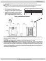
OUTDOOR INSTALLATION AND SERVICE CLEARANCES The heater must be installed outdoors such that the installation and
service clearances shown in Table3 and Figure3 are maintained. Additional installation requirements are as listed;
1. Level surface for proper draining.
2. Suitable electrical supply line. See rating plate on the heat pump units for electrical specifications. A junction box is not needed
at the heat pump; connections are made inside the heat pump electrical compartment. Minimum wire size to be selected per
NEC based on unit MCA.
3. Electric disconnect switch that will interrupt all power to the unit. This switch MUST be within line of sight of the heat pump
4. Do not install in a location where growing shrubs may in time obstruct a heater’s air flow areas (sides or top).
5. Do not install the heater where water spray from ground level can contact the heater. The water could damage coil or reach the
controls causing electrical damage.
6. Do not install under a deck.
7. Do not install within 24in of any outdoor HVAC equipment.

USEONLYGENUINEREPLACEMENTPARTS 9
51300002101RevA
8. Do not install where water may run-off a roof into the heater. A gutter may be needed to protect the heater.
CAUTION:
Make sure the heat pump is not located where large amounts of water may run-off from the roof into the unit.
Sharp sloping roofs without gutters will allow massive amounts of rainwater, mixed with debris from the roof to be forced
through the unit. Failure to follow the instructions may result in property damage and a voided warranty.
1. See table3 and figure3 for clearances.
2. If the heat pump is to be installed below a vertical
overhang such as shown in figure3, the unit must have a
minimum of 72in. [1.8m] of clearance from the top of the
heat pump to the bottom of the cover or overhang.
3. Install the heat pump a minimum of 60in. [1.5m] from the
inside wall of the pool, spa, solid fence, or permanent
barrier. Canadian installations require a minimum of 120
in. [3 m] of clearance from pool water.
Table3: Installation Required Clearances
Heat Pump Panel Outdoor
Clearance
To
p
Unobstructed
Front (control)
24-36
Rest of Perimeter
24
Figure3: Outdoor Minimum Clearances
EQUIPMENT PAD
: Place the heat pump on a level surface such as concrete or a fabricated slab (pad). This allows proper
drainage of condensation and rainwater from the base of the unit. If possible, the pad should be placed at the same level or slightly
higher than the filter system equipment pad.
FLOORING: This heater may be installed on either non-combustible flooring or combustible flooring that does not reduce the
bottom clearance of the heater. Ultralite™ or equivalent concrete-over-foam HVAC pads are acceptable.
DRAINAGE AND CONDENSATION: Condensation will be produced by the evaporator coil when the unit is heating water
and drain at a steady rate, usually three to five gallons per hour, depending upon ambient air temperature and humidity. The more
humid the conditions, the more condensation will be produced. Use the supplied condensate drain to route the condensate away
from the unit and dispose appropriately. It is easy to mistake the condensation for a water leak inside the unit. A way to verify that
the water is condensation is to shut off the unit and keep the pool pump running. If the water stops running out of the base pan, it is
condensation collecting around the unit. A quicker way is to check the water for CHLORINE. If there is no chlorine present in the
water around the unit, then it’s condensation.
36in
24in
Free
from
runoff
24in
36in
24in
24in

10 USEONLYGENUINEREPLACEMENTPARTS
51300002101RevA
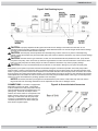
ANCHORING: The heater is equipped for installation of anchoring screws when required by local codes. Follow all
relevant Local, State and National requirements regarding wind load anchoring. When anchoring is required to secure the
heat pump to concrete pad, use the specified hardware shown in the figure4. To complete the installation use the
following;
AnchorClamps (FACTORYSUPPLIED;qty(8))
Concretetappingscrews (FIELDSUPPLIED;Tapcons®stainlesssteel,qty(8),sizetobe¼indiameter
withaminimumlengthof1‐1/2in)
Fenderwashers (FIELDSUPPLIED;stainlesssteel,qty(8),sizetobe1‐1/2in)
Figure4: Equipment Pad and Anchoring
WATER PIPING
General: The heater is for use with pool and spa/hot tub water furnished by municipal water distribution systems only. The use of
mineral water, seawater (PPM>5000), or other non-potable waters will invalidate the warranty. These heat pumps are designed for
nominal water flows through the condenser. See specifications for minimum and maximum flow requirements to ensure sufficient
heat removal and water erosion of heat exchanger tubing. The minimum flow rate is to be calculated or measured with the in-floor
cleaning system in use, if the pool is so equipped, as well as any other jets or other demands on the water flow. Flow rates above
specified maximum will create excessive pressure drop through the condenser and require unnecessarily high pumping energy.
Bypass valve setting may be accomplished by temporarily installing a flow meter on the outlet line of the heater. Then adjust the
manual bypass valve until the flowrate through the heater is within the flow rate range specified. Once the manual bypass valve is
set, note the position and remove the valve handle to prevent accidental adjustment. Failure to install an External Bypass Assembly
with flow rates above the specified maximum will void the warranty. Do not install any restriction in the water pipe between the
heater outlet and the pool with the exception of; three-way switching valve, in-line chlorinator and/or chlorinator check valve as
shown in figure5 below.
AUTOMATIC CHLORINATORS AND CHEMICAL FEEDERS: If used, a chlorinator must be installed downstream
from the heater in the pool return line and at a lower elevation than the heater as shown in Figure5. Install a separate positive seal
corrosion resistant check valve between the heater outlet and the chlorinator to prevent highly concentrated sanitizer from back
siphoning into the heater. Back siphoning may occur when the pump is shut off and a pressure differential is created.

USEONLYGENUINEREPLACEMENTPARTS 11
51300002101RevA
Figure5: Pad Plumbing Layout
CAUTION:
Improperly adjusted manual bypass valves will result in damage to the heater if the flow rates are not
maintained under all operating conditions as specified in listed SPECIFICATION. The heat exchanger will fail and this damage
will not be covered under the manufacturer’s warranty.
CAUTION:
The heat pump must be protected from back siphoning of water. If there is any chance of back siphoning,
provide a check valve between the pool and the filter pump inlet. Failure to follow the instructions may result in property damage
due to flooding.
CAUTION:
Automatic erosion type chlorinators, if used, must be installed downstream (between the heat pump and the
pool) of the heat pump, and a check valve (or Hartford Loop) installed in a manner that will not allow the raw chlorine to drain
back to the heat pump when the water pump is off. Failure to follow the instructions may result in property damage.
CAUTION:
Do not pour chemicals directly into the skimmer. It could result in damage to your system and heat pump.
Arrangement of pool system components other than as illustrated in figure5 can affect the operation of the heat pump’s water
pressure switch. Location of the heat pump above or below the elevation of the pool water surface can also affect operation of the
switch. In general, the pressure switch can be adjusted to accommodate this effect if the heat pump water connections are no more
than six (6) feet [1,8 m] below the pool water surface or no more than fifteen (15) feet [4,6 m] above it. See instructions for pressure
switch adjustment in the START-UP section of this manual. If the heat pump is installed outside of this range, an external pressure
switch may need to be installed in the plumbing upstream of the heat pump.
NOTICE: Be advised, that when pool equipment is located below the pool surface, a leak at this lower level can result in
large-scale water loss or flooding. Manufacturer is not responsible for water loss or damage it causes
.
CONNECTIONS: The heater is equipped with
detachable connectors for water. These fittings
must be installed on the heat pump water inlet and
outlet to facilitate servicing and winterizing the unit.
(See figure6). Heat sinks, heat tapes, firemen
switches, and check valves are not required on the
heater. However, if there is any chance of “back-
siphoning” of outlet water when the pump stops
running, it is suggested that a check valve and
chemical loop be used on the heater outlet pipe
down stream of bypass system.
Figure6: In Ground Included Connectors

12 USEONLYGENUINEREPLACEMENTPARTS
51300002101RevA
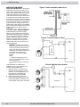
INSTALLATION ABOVE
POOL/SPA SURFACE:
If the heater is
installed less than three (3) feet above the
surface of the pool/spa water, install eyeball
fittings or directional flow fittings on the end
of the return water line to the pool/spa to
create adequate back pressure at the heater
to operate the pressure safety switch when
the pump is running. If the heater is installed
more than three (3) feet above the surface of
the pool/spa water, install a loop as shown in
Figure7 to prevent drainage of water in the
heater during a filter change. For installation
above or below the pool/spa surface, refer to
START UP section for proper pressure
switch setup.
TYPICAL POOL ARRANGEMENT:
Figure8 illustrates a typical pool piping
diagram and layout for the pool equipment.
Also shown is implementation of an optional
Gas or Solar heater system for additional
capacity. Other pool heaters, such as gas-
fired or solar-powered devices must be
installed in a parallel circuit and operated
independently (only one at a time) for your
warranty to be valid.
NOTICE - Because of the intense
heat that can be generated by gas and
solar units, isolating it with a shut-off
valve and a check valve when gas or
solar heater is in operation protects the
heat pump. Failure to follow the
instructions may result in property
damage.
Notes:
1. Isolate the heat pump from hot
water flow of heating devices such as
gas or solar heater.
2. Install bypass loop for heat pump
unit.
Figure9 illustrates a multiple heater
installation for very large pools with and
without a manual bypass valve.
1. Maintain 4-6ft [1,2-1,8 m] clearance
between the units, 2ft [0,6 m] around
perimeter, and at least 6ft [1,8 m] over
them. Refer to LOCATING THE
HEATER section for more details.
2. Install bypass loops for each unit.
3. Install union style fittings from the heat
pump CONSUMER KIT adjacent to the
unit to facilitate easy service procedures
Figure7: Heater Installation Above Pool
Figure8: Typical Plumbing to Pool
Figure9: Multiple Heater System

USEONLYGENUINEREPLACEMENTPARTS 13
51300002101RevA
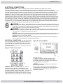
ELECTRICAL CONNECTIONS:
GENERAL INFORMATION: An external supply of power is required to operate the pool heater system. Review
SPECIFICATIONS for this heater in the GETTING STARTED section to properly size field power connections. All wiring
connections to the heater must be made in accordance with the latest edition of the National Electrical Code ANSI/NFPA 70, unless
local code requirements specify otherwise. In Canada, follow CSA C22.1 Canadian Electrical Code, Part 1. The heater must be
electrically grounded and bonded in accordance with local codes or, in the absence of local codes, with National Electrical Code,
ANSI/NFPA 70. Wiring connections must be made as shown in the wiring diagram found inside the heater cabinet, and a copy is
provided for convenience in the GETTING STARTED section at the beginning of the manual. The heater must also have an
independent ground and bond connections. There is a ground lug inside the control box adjacent to the power connections and a
bonding lug on the side of the heater. Use a solid copper conductor, size 8 or larger. Run a continuous wire from external bonding
lug to reinforcing rod or mesh. Connect a No. 8 AWG (8.4 mm2) solid copper bonding wire to the grounding lug provided on the
heat pump and to all metal parts of swimming pool or spa, and to all electrical equipment, metal piping (except gas piping), and
conduit within 5 ft. (1.5 m) of inside walls of swimming pool or spa. IMPORTANT - Reference NEC codes for all wiring standards
including, but not limited to, grounding, bonding and other general wiring procedures.
WARNING:
Risk of Electric Shock Review all safety information provided in the GETTING STARTED section
of this manual prior to servicing. Always disconnect power circuit before connecting the heat pump, or working on
the heat pump. This equipment contains wiring that carries high voltage. Contact with these wires could result in
death or personal injury and/or may also cause property damage.
WARNING:
All electrical wiring MUST be in conformance with all applicable local codes, regulations and the
National Electric Code (NEC), in particular NEC Article 680: Swimming Pools, Fountains & Similar Installations
and Article 440: Air-Conditioning & Refrigeration Equipment.
NOTICE: Manufacturer does not recommend the use of ground fault protective devices in conjunction with heat
pumps. Most service calls regarding tripping of ground fault devices, are found to be “nuisance” calls. GFCI
nuisance trips are not covered under warranty.
NOTICE: If voltage drops below 208V, this may damage the heat pump and void the warranty. Take proper
steps to ensure correct voltage at the heat pump during operation
ELECTRICAL CONNECTIONS:
Turn OFF source power
to the heat pump before working on electrical connections. Any
unused openings must be plugged and all wiring secured for
proper strain relief. The power connections are to be made on
the contactor terminals located in the control box (see Figure11
Power Connections).
Figure11: Power Connections
REMOTE ON/OFF CONNECTION: The heater is
equipped for remote ON/OFF via an independent 2-wire
connection. (See Figure12 for remote ON/OFF connection). The
unit is factory shipped with the jumper in place. The jumper can
be replaced with a remote switch to activate the unit. It is
recommended the unit be placed in Auto mode if only a remote
switch closure is used. Temperature is set at the unit controller.
Figure12: Remote ON/OFF
It is recommend if the unit is controlled remotely with external
temperature control;
For heating, set mode to Heat set thermostat to 104°F
For cooling, set mode to Cool set thermostat to 65°F.
The remote on/off can then activate the unit as needed for
remote temperature control operation.
NOTICE: Pump must be running for unit to operate with
remote control connection.
All remote wiring must be run in a conduit separate from
incoming power. Use 22 AWG wire for runs less than 30 feet.
Use 20 AWG wire for runs over 30 feet. The maximum
allowable run is 200 feet.

14 USEONLYGENUINEREPLACEMENTPARTS
51300002101RevA
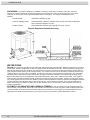
CHECK-OUT & START-UP
GENERAL: After completing the installation connections to the pool heater, follow the procedures outlined below to ensure that
the pool heater is functioning properly. Before proceeding, MAKE CERTAIN there are no water leaks in any plumbing connections
or piping and water flow is within the proper flow rate ranges. The heater is equipped with a control system that automatically
monitors the water temperature set points and safety devices. As water conditioning is needed, it turns on the compressor to start
the appropriate transfer of heat to the water. Figure13 provides a summary of heater components and their locations in the system.
Check that the pump is operating and the system is filled with water prior to starting the heater.
Figure13: Location of Components (heating operation flow shown)
The heat pump takes heat from the environment and uses it to heat the pool water. During heat pump operation, high temperature,
high-pressure sub cooled liquid Refrigerant (A) is throttled by Metering Device (TXV) and turned into low temperature, low-pressure
saturated liquid (B). The two-phase Refrigerant flows through the Air Coil (Evaporator), where the liquid refrigerant evaporates into
vapor by absorbing heat from the surrounding air. At the outlet of the Air Coil (Evaporator) it becomes a low temperature, low-
pressure superheated vapor (C). The Compressor receives this flow at the suction line (D), and compresses it into a high
temperature, high pressure superheated vapor, which is discharged from the Compressor (E) and flows through the reversing valve
into the Water Heat Exchanger (Condenser). The heat carried by the flow is then released to the pool water. At the same time, the
high temperature, high-pressure superheated vapor is then condensed back to high-pressure sub cooled liquid (A), which
completes the cycle. The water, which is being forced through the Water Heat Exchanger (Condenser) by the pool pump, is thus
heated as it passes through.
HEAT PUMP PROTECTION FEATURES: These heat pumps are equipped with safeguards that will stop heater operation
to protect the unit in case of the following events:
• Excessively high refrigerant pressure
• Excessively high water temperature
• Loss of refrigerant
• Evaporator Freeze-up
• Low Ambient Temperature
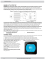
CONTROL SETUP
This pool heater is equipped with a digital thermostat which allows the user to select the desired water temperature. The heater will
then function automatically to maintain the desired temperature. The heater has 3 modes of operation:
1. HEATING: in this mode, the heater will automatically function to manage a minimum water temperature setting.
2. COOLING: in this mode, the heater will automatically function to manage a maximum water temperature setting.
3. AUTO: In this mode the heat pump will automatically respond to either a call for heating or cooling as described above.
USER INTERFACE PANEL AND INPUTS:The
control displays temperatures, mode selections,
diagnostic codes and accepts user inputs
.
Display
When power is supplied to the heat pump
unit, the display will show sensor temperature (in degrees
F or C), operation mode and other useful information
.
ON/OFF Button
Press the Circular Touch Button:
Press for 0.5s for system ON (Blue Screen) and OFF
(Black Screen).
Press for 5s to lock and unlock the screen. The Circular
Touch Button will also cancel the present selection when
making adjustments
.
Figure14: User Interface Panel

USE ONLY GENUINE REPLACEMENT PARTS 15
51300002101 RevA
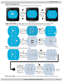
FUNCTION SELECTION
From the main interface screen, slide left or right to select the function selection screens.
Page One Interface
This page allows user to select operational mode (Heating, Auto, Cooling), target
temperature setting, silent mode and silent timing. Mode and temperature selection are shown below.
Page Two Interface
This page allows user to set system time, set aux timer operation, display faults and review
system parameters. Setting system time is shown below
TWO-SPEED PUMP: In a few cases the flow from a two-speed pump is below the minimum required to operate the water flow
84
85
83
83
Temp Setting
.5
.0
.5
.0
83
83
84
82
82
Temp Setting
.5
.0
.5
.0
.0

16 USEONLYGENUINEREPLACEMENTPARTS
51300002101RevA
switch on the heater. In these cases the pump must be run at high speed to operate the heater. If the pump and piping arrangement
are such that the required minimum flow cannot be obtained, do not attempt to operate the heater. Correct the installation.
NOTICE:
Heater installation, checkout, and start-up should now be completed. BE SURE to leave this manual with the pool
owner.
MAINTENANCE & SERVICE
PERIODIC INSPECTION: The heater is designed and built for long performance life when installed and operated according to the
manufacturer’s directions. Regular inspection by qualified service personnel is recommended to keep the heater working properly.
The following inspection points are suggested to help maximize heater life.
1. Periodically check the fan discharge area. The fan discharge must never be obstructed in any way and minimum clearances
must be observed. Remember that shrubs grow and in time may obstruct
2. Keep the entire pool heater area clean and free of all debris, corrosive materials, and other flammable vapors and liquids.
Remove any leaves or paper from around the heater.
3. Do not store chlorine, other pool chemicals, or other corrosives in the vicinity of the heater.
4. Do not use the heater if any part has been under water. Contact a qualified service technician to inspect the entire heater and
replace any part of the control system that was under water. If heater has been totally submerged in water it must be removed
and the entire heater must be replaced.
5. An inspection program is a good preventative maintenance measure. Keep this manual in a safe place for future reference for
yourself as well as for a service technician to consult when inspecting or servicing the heater. Additional inspection procedures
to be performed by a qualified service technician.
WATER CHEMISTRY:
WARNING: WATER CHEMISTRY. Failure to maintain proper water chemistry may cause premature heat exchanger
damage or failure
The heat exchanger in your pool heater is made from the highest quality of materials. The titanium condenser is a premium material
and the processes used to manufacture the heat exchanger are state of the art in pool heater design and manufacture. However, it
remains vital that the heat exchanger be protected from damaging or corrosive chemicals, insufficient water flow or improperly
balanced water chemistry. Heat exchanger damage or failure resulting from improper flow, improperly balanced pool water or the
improper addition of sanitizer into the water is NOT covered under the terms of the warranty. The following factors are critical to
heat exchanger protection. Follow these guidelines to help prevent pre-mature damage or failure to your heater and heat
exchanger.
1. WATER FLOW THROUGH HEATER Water must be flowing through the heater at the minimum rated flow rate during operation.
Check that the pump is operating and the system is filled with water and purged of all air prior to starting the heater. The
minimum rated flow rates are listed in the specifications section. Some installations may require an adjustment to the water
pressure switch for proper low-flow protection. Test your system and if necessary, adjust the water pressure switch as described
in WATER TESTING SECTION OF MANUAL.
Table4: Water Chemistry
Chemical
Recommended
Level
Effect of Low Levels Effect of High Levels
Chlorine 1 - 3 ppm
hazy water, algae growth,
bacteria causing infections
swimmer irritation, bleaching of
clothes/hair, corrosive to heat
exchanger
Bromine 2 - 4 ppm
pH 7.4 - 7.6
corrosive to heat exchanger,
swimmer irritation
cloudy water, scaling of heat
exchanger, reduced sanitizer
effectiveness
Total Alkalinity 80 - 120 ppm
corrosive to heat exchanger,
large fluctuations in pH
scaling of heat exchanger
Calcium
Hardness
200 - 400 ppm corrosive to heat exchanger scaling of heat exchanger
Salt 2700 - 5000 ppm poor salt chlorinator performance corrosive to heat exchanger
2. WATER CHEMISTRY The chemistry balance and mineral content of swimming pool and spa water changes rapidly due to the
addition of sanitizing chemicals, user loads, exposed rain, runoff and the amount of sun - to name a few. Improper chemistry
(See Table4) balance and mineral content can cause scaling and deposits to form on pool walls, in the filtration system, in the
heat exchanger tubes and additionally can promote corrosive action to all metals in the water path. Changing spa water regularly

USEONLYGENUINEREPLACEMENTPARTS 17
51300002101RevA
and maintaining the correct chemical balance in your pool/spa will keep the pool/spa safe and sanitary, and will help the heat
exchanger longevity. Use a 4-way pool/spa water test kit to check your water frequently (at least weekly). Use the following
guidelines to help maintain proper water chemistry:
3. SKIMMER CHLORINATION Placing chlorine or bromine Tablets directly into the skimmer may result in high chemical
concentrations flowing through the heater. DO NOT place chlorine or bromine Tablets in the skimmer.
4. CHLORINATOR INSTALLATION Chlorinators must be installed downstream of the heater, and a check valve must be installed
between the heater and chlorinator to prevent high chemical concentrations from back flowing into the heater. Make sure your
piping arrangement meets the chlorinator installation requirements shown on page 26.
5. USE BYPASS Until water chemistry is properly balanced, so that corrosive and potentially damaging water will not flow through
the heater and therefore the heat exchanger. Close the bypass valve once the water is properly balanced.
WARNING BYPASS. Failure to close the bypass valve when attempting to operate the heater will result in extensive damage
to the heat exchanger
Ensure water flow through the heater is restored before operating the heater. A bypass feature is also advantageous for service
needs and for the ability to remove the heater from the water path when not heating.
WINTERIZATION:
In moderate climates, the heater can continue to operate during short-term cold spells. Do not use the heater to maintain the water
temperature just above freezing or for freeze protection. Care must be taken to avoid freeze-up in the heater. When it is used during
freezing weather, the pump must run continuously. The heater is not warranted against freeze-ups. In regions where freezing
temperatures are encountered, all water must be drained from the heater when it is out of service, to prevent damage to the heater
and piping. Draining the heat exchanger is recommended as part of the season’s shutdown procedures.
NOTICE: A heater damaged by freezing is not covered under the manufactures warranty.
DRAINING THE HEAT EXCHANGER: This procedure applies to installations where the heater is located higher than the pool water
level. If itis necessary to drain a pool heater located below the pool water level, you must either partially drain the pool, or isolate the
pool heater from the pool using valves, then perform draining the heat exchanger.
1. Set the heater to OFF mode.
2. Turn the electricity to the heater OFF at the circuit breaker panel.
3. Be sure the circulating pump is OFF.
4. If no drain plug is provided, open lower inlet water union and allow all water to drain from the heater.
5. Re-install the drain plug or reattach the water union.
SPRING START-UP: This procedure should be performed annually to ready your heater for the upcoming season. In addition to
the steps outlined below, it is recommended that a PERIODIC INSPECTION also be performed.
1. Inspect and clean the heater, being sure the heater is free of leaves and debris prior to startup.
2. Properly attached inlet and outlet piping and confirm the drain valve is closed.
3. Turn the filtration system pump ON and allow the system to run long enough to purge all the air from the lines.
4. Turn the electricity to the heater ON at the circuit breaker panel.
5. Set the heater to H mode and adjust the set point to the desired temperature setting.
6. If operating difficulties are encountered, contact a qualified service company for assistance.
COMPONENT SERVICE
NOTICE: Only qualified service technicians, with appropriate test equipment, should be allowed to service the heater. For
conditions where refrigerant must be managed, an EPA certified technician is required. All of the components that comprise the
system have an effect on heater operation. Before proceeding with heater related troubleshooting tips, be certain that the pump
is operating correctly, the filters and strainers are not blocked, the valves in the piping are properly positioned, and the time
clocks are properly set.
WARNING: EXPLOSION HAZARD
Do not attempt to repair broken or faulty components of this heater. Do
not modify the heater or its components in any manner. To do so may result in a malfunction that could result in
death, personal injury, or property damage. Check with the pool owner to see if any part of the heater has been
under water. Replace any electrically operated component that has been under water
.
WARNING:
Risk of Electric Shock Review all safety information provided in the GETTING STARTED
section of this manual prior to servicing. Always disconnect power circuit before connecting the heat pump, or
working on the heat pump. This equipment contains wiring that carries high voltage. Contact with these wires
could result in death or personal injury and/or may also cause property damage.
TROUBLESHOOTING
TROUBLESHOOTING: See Table 5: Troubleshooting Lookup Chart.
ERROR and OPERATION CODES: See Table 6: Display Code Index.
AUTOMATIC RESET TIME: The heater will automatically reset when an error condition is corrected and resume operation.

18 USEONLYGENUINEREPLACEMENTPARTS
51300002101RevA
NOTICE:
These instructions are intended for the use of qualified personnel trained and experienced in the installation
and servicing of this type of heating equipment and its related system components. Some states may require installation
and service personnel to be licensed. Persons not qualified should not attempt to repair this equipment according to these
instructions. These instructions and procedures are not for the use of “do-it-yourself” consumers.
NOTICE:
As a preliminary check, make sure that all wire connections are clean and tight and that all wiring conforms to
the wiring diagram.
INTERNAL WIRING: If the heater display is blank after the electrical has been installed, refer to Troubleshooting Lookup Chart
to determine the cause. Note, the cable between the display board and the control board is keyed to ensure correct connection.
WARNING: To avoid possible outer jacket damage or injury: (1) no materials should be stored against the jacket and
(2) care should be taken to avoid unnecessary contact (especially by children) with the jacket.
Table 5: Troubleshooting Lookup Chart
Problem Possible Cause Possible Solution(s)
Unit is not operating.
No power to unit Make sure power is on.
Breaker is tripped Check the breaker / see note above
Thermostat too low Turn thermostat up until unit comes on
3 minute compressor delay timer
still runnin
g
Be sure the delay has passed
Low water flow
Make sure filter is clean
Make sure filter
p
um
p
is on
Unhook cleaning devices
Outside temperature too low
Check outside ambient temperature or wait for warmer
temperatures to operate. (refer to Operating section)
Fan not functioning Call for service.
Heat pump is running
but Display not on.
System Component failure. Call for service.
Heat pump runs
continually
Thermostat set too high for ambient
temperature
Turn thermostat down
Evaporator is dirty. Clean by running tap water over the coil without additional
nozzle attachment. Do not use pressurized water as it can
damage the coil and void warranty.
Electrical component failure Turn off pump. If the unit is still running after 3 minutes, turn
off the power to the unit and call for service.
Heat pump is cycling
(on / off too quickly)
Bad bypass valve or improper
water flow
Ensure water flow is sufficient (is the filter pump running
continually?) If heat pump continues to cycle, turn unit off to
prevent compressor damage.
Low refrigerant, low ambient temp,
or high humidity with low ambient
temp
Check evaporator coil for severe frost. Turn unit off to
p
revent com
p
ressor dama
g
e.
If heat pump continues to cycle, turn unit off to prevent
compressor damage. Call for service.
Water is coming from
bottom of unit
Condensation
This is normal and there is no reason to be concerned
Possible water leak
Turn the unit off for several hours, but leave the filter pump
running continuously. If water quantity decreases, then it is
only condensation. Otherwise there is a possible leak.

USEONLYGENUINEREPLACEMENTPARTS 19
51300002101RevA
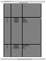
Table 6: Display Code Index
Display Malfunction Possible Cause Information
(blank)
No power to heat pump
Tripped circuit breaker/
no power supply
Check breaker and ensure that the unit is
properly installed.
Faulty electrical
component
Call for service.
Unit will not turn on
Display module failure Call for service.
E01
High Pressure Switch,
circuit open.
Low water flow
Check water flow to heat pump. Ensure pool
pump is on.
Clean your filter
Make sure all valves are fully open and
bypass valve is closed
Turn off other water flows; fountains, etc.
High water temp
Check pool temp. Confirm within allowable
limits for heating and cooling.
Call for service.
E02
Low Pressure Switch,
circuit open.
Air flow obstruction
Remove debris and other items restricting air
flow to heat exchanger
Low Ambient
Temperature cutoff
Wait for outside temperature to reach 20°F.
Unit low on refrigerant Call for service.
E03
Flow Switch circuit open
Low or no water flow or
remote on/off in use
Check water flow to heat pump. Ensure pool
pump is on.
Make sure all valves are fully open and
bypass valve is closed
Clean your filter
E05
Water temperature
freeze protection
Water freeze warning
activated
Unit can’t keep water above freeze point
E06
Unit water temperature
rise to great
Low water flow
Call for service
E07
Freeze up during
cooling mode
Low water flow
Call for service
E19
Primary anti-freezing
protection heating mode
Ambient temperature too
low for operation
Call for service
E29
Primary anti-freezing
protection heating mode
Ambient temperature too
low for operation
Call for service
P01, P02
Inlet or Outlet
temperature sensor
failure
Sensor short circuit, open
circuit or not connected
Call for service or replace sensor
P04
Ambient temperature
sensor failure
Sensor short circuit, open
circuit or not connected
Call for service or replace sensor
P05, P15
Coil temperature
sensors failure
Sensor short circuit, open
circuit or not connected
Call for service or replace sensor
P07
Suction temperature
sensor failure
Sensor short circuit, open
circuit or not connected
Call for service or replace sensor
P081
Discharge temperature
sensor failure
Sensor short circuit, open
circuit or not connected
Call for service or replace sensor
P082
Discharge temperature
out of range
Compressor overloaded
Call for service or replace sensor
PP
Pressure sensor failure
Sensor short circuit, open
circuit or not connected
Call for service or replace sensor

20 USEONLYGENUINEREPLACEMENTPARTS
51300002101RevA
Table 6: Display Code Index
Display Malfunction Possible Cause Information
F02
Inverter offline
Inverter to control board
communication failure
Check the communication cable for
connection.
F04
Compressor start
Failure
Compressor power
overload
Call for service
F05, F051
Fan fault
Motor feedback open
circuit or short circuit
Call for service
F06, F26
Inverter overcurrent fault
Inverter power high
Restart unit, Call for service
F10
Inverter under voltage
fault
Unit supply voltage too
low
Confirm ample power supply to unit, Call for
service
F19, F20,
F22
Inverter over
temperature
Inverter temperature out o
f
range or near limits
Restart unit, Call for service
F25
Inverter EEPROM
Warning
Inverter check-sum
communication error
Restart unit, Call for service
Page is loading ...
Page is loading ...
Page is loading ...
Page is loading ...
-
 1
1
-
 2
2
-
 3
3
-
 4
4
-
 5
5
-
 6
6
-
 7
7
-
 8
8
-
 9
9
-
 10
10
-
 11
11
-
 12
12
-
 13
13
-
 14
14
-
 15
15
-
 16
16
-
 17
17
-
 18
18
-
 19
19
-
 20
20
-
 21
21
-
 22
22
-
 23
23
-
 24
24


HeatPro HeatPro VS HP50951T User manual
- Category
- Above ground pool accessories
- Type
- User manual
- This manual is also suitable for
Ask a question and I''ll find the answer in the document
Finding information in a document is now easier with AI
Other documents
-
Raypak PS10355ti-E-HC User manual
-
 Energy Tech Laboratories 8357 User manual
-
Raypak 5100 User manual
-
-
-
 Energy Tech Laboratories 5356, 5357, 5358, 6356, 6357, 6358, 8357 & 8358 User manual
-
Rheem Classic Heat Pump Pool Heaters Operating instructions
-
-
-
 G&F Manufacturing Gulfstream Troubleshooting guide


