
P/N 1010881 Rev. G 03/12
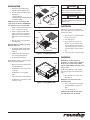
MS-150
owner’s manual
miracle steamer
Manufacturing Numbers:
9100421, 9100429
www.ajantunes.com
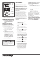
POWER
UP
READY
DOWN
PROGRAM
START/STOP

2
P/N 1010881 Rev. F 03/12
SERVICE/TECHNICAL
ASSISTANCE
If you experience any problems with the
installation or operation of your unit, contact
your local Roundup Authorized Service Agency.
Fill in the information below and have it
handy when calling your Authorized Service
Agency for assistance. The serial number is on
the specification plate located on the rear of
the unit.
Use only genuine Roundup replacement parts
in this unit. Use of replacement parts other
than those supplied by the manufacturer will
void the warranty. Your Authorized Service
Agency has been factory trained and has a
complete supply of parts for this unit.
Visit www.ajantunes.com or contact the fac-
tory at 1-630-784-1000 to locate your nearest
Authorized Service Agency.
Refer to the service agency directory packaged
with your manual and fill in the information
below.
GENERAL
The Miracle Steamer produces steam using
plain tap water for quick heating and recon-
stituting of food items. Simple push-button
action delivers a fully adjustable impulse
of steam. Because the amount of steam is
consistent, it removes the guesswork and
produces a uniform finished product from one
operator to the next.
This manual provides the safety, installation,
and operating procedures for the Miracle
Steamer. We recommend that all information
contained in this manual be read prior to
installing and operating the unit.
The Miracle Steamer is manufactured from the
finest materials available and is assembled
to Roundup’s strict quality standards. This
unit has been tested at the factory to ensure
dependable trouble-free operation.
WARRANTY INFORMATION
Please read the full text of the Limited
Warranty in this manual.
If the unit arrives damaged, contact the car-
rier immediately and file a damage claim with
them. Save all packing materials when filing a
claim. Freight damage claims are the respon-
sibility of the purchaser and are not covered
under warranty.
The warranty does not extend to:
• Damages caused in shipment or dam-
age as result of improper use.
• Installation of electrical service.
• Normal maintenance as outlined in
this manual.
• Malfunction resulting from improper
maintenance.
• Damage caused by abuse or careless
handling.
• Damage from moisture into electrical
components.
• Damage from tampering with, removal
of, or changing any preset control or
safety device.
General .................................................. 2
Warranty Information ............................. 2
Service/Technical Assistance ................... 2
Important Safety Information ................. 3
Warnings ................................................ 3
Specifications ......................................... 4
Installation ............................................. 5
Electrical ................................................. 5
Plumbing ................................................ 5
Operating Instructions ............................ 6
Programming ......................................... 6
Generator Temperature .......................... 7
Daily Maintenance ................................. 7
Monthly Maintenance ............................ 8
Troubleshooting...................................... 9
Wiring Diagram ...................................... 11
Replacement Parts .................................. 12
Limited Warranty .................................... 16
Table of Contents
Purchased From
Date of Purchase
Authorized Service Agency
Model Number
Name
Serial Number
Phone Number
Manufacturing Number
Address
IMPORTANT
A.J. Antunes & Co. reserves the right
to change specifications and product
design without notice. Such revisions do
not entitle the buyer to corresponding
changes, improvements, additions or
replacements for previously purchased
equipment.
IMPORTANT
Keep these instructions for future ref-
erence. If the unit changes ownership,
be sure this manual accompanies the
equipment.

3
P/N 1010881 Rev. F 03/12
IMPORTANT SAFETY
INFORMATION
Use the following guidelines for safe opera-
tion of the unit.
• Read all instructions before using
equipment.
• For your safety, the equipment is fur-
nished with a properly grounded cord
connector. Do not attempt to defeat
the grounded connector.
• Install or locate the equipment only
for its intended use as described in
this manual. Do not use corrosive
chemicals in this equipment.
• Do not operate this equipment if it
has a damaged cord or plug, if it is
not working properly, or if it has been
damaged or dropped.
• This equipment should be serviced by
qualified personnel only. Contact your
nearest Authorized Service Agency for
adjustment or repair.
• Do not block or cover any openings on
the unit.
• Do not immerse cord or plug in water.
• Keep cord away from heated surfaces.
• Do not allow cord to hang over edge
of table or counter.
• Turn the power off, unplug the power
cord, and allow unit to cool down
before performing any service or
maintenance on the unit.
• The procedures in this manual may
include the use of chemical products.
These chemical products will be
highlighted with bold face letters fol-
lowed by the abbreviated HCS (Hazard
Communication Standard). See Hazard
Communication Standard manual for
the appropriated Material Safety Data
Sheets (MSDS).
• The equipment should be grounded
according to local electrical codes to
prevent the possibility of electrical
shock. It requires a grounded recep-
tacle with separate electrical lines,
protected by fuses or circuit breaker of
the proper rating.
• All electrical connections must be in
accordance with local electrical codes
and any other applicable codes.
• Do not clean this appliance with a
water jet.
WARNINGS
Be advised of the following warnings when
operating and performing maintenance on
this unit.
• If the supply cord is damaged, it must
be replaced by the manufacturer or its
service agent or a similarly qualified
person in order to avoid a hazard.
• Do not modify the power supply cord
plug. if it does not fit the outlet, have
a proper outlet installed by a qualified
electrician.
• Do not use an extension cord with this
appliance.
• Electrical ground is required on this
appliance.
• Check with a qualified electrician if
you are unsure if the appliance is
properly grounded.
• If a chemical cleaner is used, be sure
it is safe to use on cast aluminum.
Observe all precautions and warnings
on product label.
• Inspection, testing, and repair of elec-
trical equipment should only be per-
formed by qualified service personnel.
• This equipment is to be installed to
comply with the basic plumbing code
of the Building Officials and Code
Administrators, Inc. (BOCA) and the
Food Service Sanitation Manual of the
Food and Drug Administration (FDA).
• To ensure proper steaming character-
istics, some calcium/mineral deposits
must be present on the generator
surface. If, during cleaning, the surface
does become free of calcium/mineral
deposits, add plain tap water to the
surface and allow it to boil off. This
may have to be repeated several times
to ensure proper steaming characteris-
tics by creating a thin layer of deposits
on the surface.
• Do not use a sanitizing solution or
abrasive materials. The use of these
may cause damage to the stainless
steel finish.
• Chlorides or phosphates in clean-
ing agents (e.g. bleach, sanitizers,
degreasers or detergents) could cause
permanent damage to stainless steel
equipment. The damage is usually in
the form of discoloration, dulling of
metal surface finish, pits, voids, holes,
or cracks. This damage is permanent
and not covered by warranty.
• The following tips are recommended
for maintenance of your stainless steel
equipment:
• Always use soft, damp cloth for
cleaning, rinse with clear water
and wipe dry. When required,
always rub in direction of metal
polish lines.
• Routine cleaning should be done
daily with soap, ammonia deter-
gent, and water.
• Stains and spots should be
sponged using a vinegar solution.
• Finger marks and smears should be
rubbed off using soap and water.
• Hard water spots should be
removed using a vinegar solution.

4
P/N 1010881 Rev. F 03/12
SPECIFICATIONS
Model &
Mfg. No.
Volts Watts Amps Hertz
Plug
Description
MS-150
9100421
230 3300 14.4 50/60
IEC-309 16 Amp.,
230 Volt
Pin & Sleeve
MS-150
9100429
230 3300 14.4 50/60
CEE 7/7 16 Amp.,
250 Volt
Model &
Mfg. No.
Agency Approvals
MS-150
9100421
9100429
A
S
D
L
I
S
T
E
CM
O
I
N
N
I
T
A
T
C
T
I
S
L
US
E
D
D
L
I
S
T
E
C US
I
N
T
E
R
T
E
K
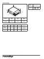
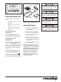
Model No.
Width
(A)
Depth
(B)
Height
(C)
MS-150
9100421
9100429
21"
(533 mm)
21 3/8"
(543 mm)
10 1/4"
(260 mm)
READY
A
C
B

5
P/N 1010881 Rev. F 03/12
INSTALLATION
1. Remove the unit and all packing
materials from the shipping carton.
2. The unit should come with the items
listed below:
• Owner’sManual
• AuthorizedServiceAgencyDirectory
• SpatulaAssembly
NOTE: If any parts are missing or dam-
aged, contact A.J. Antunes IMMEDIATELY
at 1-800-253-2991 or 1-630-784-1000.
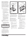
3. Remove all packing materials and pro-
tective coverings from the unit.
4. Remove and wash the Wire Trivet,
Spatula, Spatula Liner, and Drip Pan
(Figure 1) in soap and water. Rinse
with clean hot water and allow to air
dry.
5. Wipe all surfaces of the unit with a
hot, damp cloth.
NOTE: Do NOT use a dripping wet cloth.
Wring out before use.
6. Assemble the Handle, Handle Guard
and Mounting Bolt to the Spatula
(Figure 2).
7. Install the Wire Trivet into the side
slots on the Spatula (Figure 2).
8. Re-install all removed parts.
When placing the unit into service, pay atten-
tion to the following guidelines:
• Make sure power is off and the unit is
at room temperature.
• Do NOT block or cover any openings
on the unit.
• Do NOT immerse cord or plug in
water.
• Keep cord away from heated surfaces.
• Do NOT allow cord to hang over edge
of table or counter.
Spatula
Wire Trivet
Drip Pan
Spatula Liner
Figure 1. Washing Parts
Figure 2. Assembling Handle
Bolt
Handle
Spatula
Handle Guard
Wire Trivet
ELECTRICAL
Plug the power cord into the appropriate
power outlet. Refer to the specification plate
for the proper voltage.
1. Place the unit on a sturdy, level table
or other work surface.
2. Turn off the power.
3. Ensure that the line voltage corre-
sponds to the stated voltage on the
units specification label and power
cord warning tag. If you are unsure of
your Line Voltage, contact an electri-
cian.
4. Connect the unit to the power supply.
WARNING
Be sure to follow all the precautions, proce-
dures, and safety steps listed in the Important
Safety Information section of this manual.
WARNING
All electrical connections must be in accor-
dance with local electrical codes and any other
applicable codes.
PLUMBING
NOTE: Miracle Steamer models are
designed to use cold tap water. Distilled
water may be used to reduce calcium/
mineral deposit buildup and reduce main-
tenance costs.
The MS-150 models have a self-contained
water tank. To fill the self-contained water
tank:
1. Open the Tank Cover on top of the
unit (Figure 3).
NOTE: Make sure filter inside tank is
installed properly.
2. Pour in cold tap water. The tank will
hold approximately 3 quarts (2.81
liters).
3. Close the Tank Cover.
NOTE: Do NOT overfill the unit’s water
tank. Only fill the tank to 90% full.
READY
Figure 3. Filling Water Tank
Filter
Tank Cover
Tank

6
P/N 1010881 Rev. F 03/12
OPERATING INSTRUCTIONS
1. Turn the power on and allow the unit
to preheat for approximately 20-30
minutes.
NOTE: Do NOT push any button dur-
ing warmup time. The flashing green
Ready Light indicates that the unit is not
warmed up. The Ready Light will become
steady when the unit is warmed up.
2. Pull out the Spatula and set the prod-
uct to be steamed onto the Spatula.
3. Push the Spatula fully into the
steamer.
4. Single Shot: Press and release the
Operate button, then wait 20 seconds
for the steam to penetrate the product.
Timed Cycle: Press the Start/Stop
button to begin the steaming cycle.
The display will count down to zero
and an audio signal will sound at the
end of the steaming cycle.
5. Remove steamed product.
PROGRAMMING
CYC (Total Cycle Time) refers to the total
programmed steam time set for the product.
SHO (Shot Interval Time) refers to the time set
between shots of steam during a complete cycle.
H2O setting (Steam Shot Time) refers to the
water volume consumed during each water
pump activation.
The amount of steam produced by your
Miracle Steamer depends on the amount of
water sprayed onto the steam generator.
Flooding of the generator may occur if the
H2O setting is too high. To prevent flooding,
the Shot Interval Time (SHO) can be increased
to allow more time for generator heat recov-
ery. Adjustments should be made to both
values to determine the best settings for your
cooking needs.
1. Turn the unit on. The unit displays the
factory programmed Total Cycle Time
in minutes and seconds.
2. Press and release
to change the
control from OPERATION to PROGRAM
mode.
3. To change the Total Cycle Time in
minutes, press ▲ or ▼ to change the
time.
4. Press and release
again, and press
▲ or ▼ to change the Total Cycle
Time in seconds.
5. To change the SHO factory settings,
make sure the control is in PROGRAM
mode, then press and hold both ▲
and ▼ simultaneously for 1-2 seconds
and release. “SHO” will be displayed.
6. Press and release
and then press
▲ or ▼ to change the SHO in seconds.
7. Press and release
again and press
▲ or ▼ to change the SHO in minutes.
8. Press and release
again and
“H2O” will be displayed.
9. To change the H2O (Steam Shot time),
press and release the Program button
again to display the setting. Use▲ or
▼ to increase or decrease the time.
10. Press the Start/Stop or Operate but-
tons to store the changes, exit the
PROGRAM Mode, and initiate the
cooking cycle.
WARNING
To avoid injury, be careful when pulling the
spatula out from the unit. Be sure to allow
steam to escape before putting hands or
face over the steamer.
IMPORTANT: Miracle Steamers are factory
programmed for the following recom-
mended settings:
• Total Cycle Time (CYC) = 15 min., 00
secs. (Range: 3 seconds to 99 minutes
59 seconds)
• Shot Interval Time (SHO) = 00 min., 20
secs. (Range: 3 seconds to 5 minutes
59 seconds)
• Steam Shot Time (H2O) = 1_00
(Range: 0_10 second to 2_50)
NOTE: The Start/Stop or Operate buttons
may be pressed at any time during pro-
gramming to store the changes and exit
the PROGRAM Mode.
NOTE: If a change is not made within 5
seconds at any time during the program-
ming process, all changes made up to that
point are stored in memory and the con-
trol reverts to the OPERATION Mode.
UP DOWN PRGM
START/STOP
POWER
READY
SINGLE SHOT
Ready
Light
Power
Switch
Operate
Button
Message
Display
Start/Stop
Button
Figure 4. Operating Controls

7
P/N 1010881 Rev. F 03/12
DAILY MAINTENANCE
1. Turn the power off, unplug the power
cord, and allow the unit to cool down
before proceeding.
2. Remove the Spatula, Liner, Drip Pan,
Top Cover, and Steam Vent (Figure 6).
3. Wash items in hot, soapy water and
then rinse and wipe dry.
4. Wipe down the food compartment
and the entire exterior of the unit with
a clean, hot, damp cloth (not dripping
wet) and wipe dry.
5. Reinstall the Steam Vent first, followed
by the remaining items.
NOTE: Failure to properly clean and dry
the above mentioned items prior to reas-
sembling may result in the accumulation
of water/moisture overnight. This may
lead to permanent damage of the equip-
ment’s finish and its accessories. This
damage is not covered by warranty.
NOTE: Frequency of cleaning is deter-
mined by water conditions, usage and
water filtration systems.
CAUTION
Do not use a sanitizing solution or abrasive
materials. The use of these may cause dam-
age to the stainless steel finish.
CAUTION
If a chemical cleaner is used, be sure it is
safe to use on cast aluminum. Observe all
precautions and warnings on product label.
WARNING
Turn the power off, unplug the power cord, and
all the unit to cool down before performing
any service or maintenance.
WARNING
Be sure to follow all the precautions, proce-
dures, and safety steps listed in the Important
Safety Information section of this manual.
Steam Vent
Spatula
Drip Pan
Spatula Liner
Top
Cover
Figure 6. Daily Cleaning–MS-150
GENERATOR TEMPERATURE
The unit has three Generator temperature
options.
• Display of current Generator casting
temperature
• Changing of Generator setpoint tem-
perature
• Changing temperature units from
Fahrenheit (°F) to Celsius (°C) and
vice versa.
DISPLAYING GENERATOR
TEMPERATURE
Press and hold to verify the actual
Generator temperature. The unit will display
the actual Generator temperature (Figure 5).
CHANGING GENERATOR
TEMPERATURE
To change the Generator setpoint tempera-
ture, press and hold
and simultaneously
for three seconds (Figure 5). Then, press
and
to raise or lower the temperature. Release
the buttons when the desired temperature
is reached. After 10 seconds, the display will
return to 15:00.
CHANGING TEMPERATURE DISPLAY
To change the display from Fahrenheit (°F)
to Celsius (°C), press and hold
and
simultaneously for three seconds. Repeat the
process to reverse from Celsius to Fahrenheit.
Figure 5. Generator Temperature
UP
DOWN
PROGRAM START/STOP
400F

8
P/N 1010881 Rev. F 03/12
MONTHLY MAINTENANCE
The Miracle Steamer utilizes an open steam
Generator. Water sprayed onto the Generator
surface flashes into steam immediately,
but the minerals in the water stay on the
Generator surface. A small amount of calcium/
mineral deposits are needed for proper opera-
tion, but a buildup of excessive calcium/min-
eral deposits causes poor steaming efficiency
and excessive moisture (wet steam), which
will eventually severely hinder the steaming
action.
CLEANING STEAM GENERATOR
1. Turn the power off, unplug the power
cord, and allow the unit to cool down.
2. Perform the Daily cleaning, but do
NOT reassemble the unit.
3. Remove the Wing Nut, Generator
Cover, and Diffuser (Figure 7). Wash
these items in hot, soapy water, rinse
and wipe dry.
4. With the unit cool, use a wire brush
and/or scraper to loosen and remove
the excessive calcium/mineral deposits
from the Generator surface.
5. Take a wire brush and clean out any
buildup from the 28 Steam Ports
(26 vertical and 2 horizontal) of the
Generator (Figure 8). Remove the
loose buildup, wipe the Generator
with a clean, damp cloth, and reas-
semble the unit.
NOTE: If deposits are still excessive and/
or difficult to remove, refer to Steps 6
and 11.
6. Pour delimer solution (not supplied)
onto the Generator surface. Follow the
delimer manufacturer’s instructions for
proper mixture and use.
WATER TANK FILTER
The Water Tank Filter (Figure 8) is used to pre-
vent solids or food products from entering and
damaging the water pump. Inspect and clean
the Filter monthly or more regularly using the
following procedure:
NOTE: The water level should be very low
or near empty.
1. Turn the power off, unplug the power
cord, and allow the unit to cool down
before proceeding.
2. Open the Tank Door (Figure 8).
3. Remove the Filter, located inside the
tank, by pulling it upwards and out of
the bottom hole.
4. Clean the Filter by running it under tap
water. Replace the Filter if the screen is
torn or damaged.
5. Reinstall the Filter Stem into the bot-
tom hole of the tank (Figure 8).
6. Fill the Water Tank, close the Tank Door,
and test the unit.
NOTE: Do NOT overfill the unit’s water
tank. Only fill the tank to 90% full.
7. Using a sponge or a dry towel,
remove the delimer solution from the
Generator surface, then rinse with
clean water.
To ensure proper steaming characteristics,
some calcium/mineral deposits must be pres-
ent on the Generator surface. If, during clean-
ing, the surface does become free of calcium/
mineral deposits, add plain tap water to the
surface and allow it to boil off. If necessary,
repeat this process to formulate a thin coating
of calcium/mineral deposits.
CAUTION
If a chemical cleaner is used, be sure it is
safe to use on cast aluminum. Observe all
precautions and warnings on product label.
In soft water areas, it may be necessary to
add a small amount of lime to the Generator
to season it. This will ensure proper steaming
characteristics by producing a thin coating of
calcium/mineral deposits on the Generator
surface.
Seasoning mixture consists of 3/4 ounces
(25ml/ 25cc) baking soda, 3/4 ounces
(25ml/25cc) lime mixed with 1 quart
(950ml/950cc) of water. Stir mixture and pour
1/4” deep onto the hot Generator surface.
After mixture is converted to steam, the
remaining loose power can be removed.
8. Plug the power cord into the appropri-
ate outlet.
9. Turn the power on and allow the unit
to warm up for approximately 30
minutes.
10. Push and release the Operate button
or the Start/Stop button several times
to operate the steamer. This purges any
remaining delimer residue from the
Generator surface.
11. Turn the power off, reinstall all parts
and accessories, and return the unit to
service.
READY
Diffuser
Wing Nut
Generator
Cover
Figure 7. Monthly Cleaning
Generator
Steam Ports
(26 vertical and
2 horizontal)
Figure 8. Water Tank Filter
Water Tank Filter
Filter Stem
Access
Cover
with Tank
(dotted line)
Bottom
Hole
of Water
Tank
Tank Door

9
P/N 1010881 Rev. F 03/12
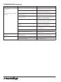
TROUBLESHOOTING
Problem Possible Cause Corrective Action
Control Display is blank (power is on
but indicator light is off).
The power cord is not correctly plugged in. Plug the power cord into the appropriate outlet.
The power cord and/or electrical plug is damaged. Inspect electrical wire, plug, and receptacle.
The main electrical panel circuit breaker is off or has
been tripped.
Reset circuit breaker. Contact your maintenance per-
son or Authorized Service Agency if it trips again.
Switch is inoperable. Contact your maintenance person or Authorized
Service Agency for service.
Control Display is blank (power is on
and indicator light is on).
Control Board is inoperable Contact your maintenance person or Authorized
Service Agency for service.
Transformer is inoperable.
Loose, burnt, or broken wires in circuit.
Unit does not heat up (Control Display
is on).
Hi-Limit Thermostat is tripped or inoperable. Reset the Hi-Limit Thermostat according to the
Operations section of this manual. If the Hi-Limit
Thermostat requires continuous resetting, contact
your Authorized Service Agency for service.
Solid State Relay is inoperable.
Thermocouple is inoperable.
Control Board is inoperable.
Steam Generator is inoperable.
Loose, burnt, or broken wires in circuit.
The unit’s main electrical panel
circuit breaker trips.
Damaged receptacle, plug, or cord; a loose connec-
tion; or an internal component failure.
Turn the power off, allow the unit to cool to room
temperature, and then restart the unit. Contact your
maintenance person or Authorized Service Agency if
the condition repeats.
Water leaking inside electrical
housing.
Pinhole leak in rubber hoses Replace hoses.
Loose or damaged water line tubes and/or fittings
inside electrical housing.
Tighten or replace tubes and/or fittings.
“ERR” appears in the Control Display. Programming and/or SHO and H2O values were
adjusted/changed improperly.
Reset the Control Board as described in the
Programming section of this manual. See Fault
Codes.
WARNING
To avoid possible personal injury and/or damage to the unit, inspection, test, and repair of electrical equipment should be performed by qualified
service personnel. The unit should be unplugged when servicing, except when electrical tests are required. Use extreme care during electrical circuit
tests. Live circuits will be exposed. If the troubleshooting steps listed below do not solve your machine’s problem, contact an Authorized Service
Agency for further assistance.

10
P/N 1010881 Rev. F 03/12
Problem Possible Cause Corrective Action
Unit heats but there is little or no
steam produced
and/or
The product requires more steaming
than usual.
Filter Strainer is restricted. Check and clean the Filter Strainer as described in
the Maintenance section of this manual.
Unit is not being cleaned properly (daily/monthly). Clean unit daily and monthly as described in the
Maintenance section of this manual.
Programming and/or SHO, H2O values were adjusted/
changed improperly.
Reprogram the SHO and H2O values as described in
the Programming section of this manual.
Insufficient or excessive calcium/mineral deposits on
the Generator surface.
Verify that thin layer of calcium/mineral deposits
is present on the Generator surface. Refer to the
Maintenance section of this manual.
Generator surface is bare. Generator surface must have a thin calcium/
mineral coating for proper steaming. Refer to the
Maintenance section of this manual.
Generator Steam Ports are
restricted.
Clean the Steam Ports as described in the
Maintenance section of this manual.
Generator Cover is warped or loose. Verify that the Generator Cover Wing Nut is tight.
If noticeable steam escapes around the Generator
Cover, replace the cover.
Generator Diffuser is missing. Install Generator Diffuser or replace if missing.
Generator surface temperature is too low. Verify Generator surface temperature to be 380–
420°F (193-–215°C).
Excessive condensation in Food
Compartment.
Programming and or SHO and H2O values were
adjusted improperly.
Reprogram the SHO and H2O values as described in
the Programming section of this manual.
Steam coming out around top covers
or sides.
Generator Cover’s Wing Nut is loose. Tighten Wing Nut.
Generator Cover is warped. Replace Generator Cover.
TROUBLESHOOTING (continued)

11
P/N 1010881 Rev. F 03/12
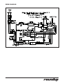
WIRING DIAGRAM

12
P/N 1010881 Rev. F 03/12
READY
64
11
18
20
45
36
21
66
65
6
7
8
10
12
13
24
62
38
35
70
57
54
54
54
42
41
40
39
29
17
15
57
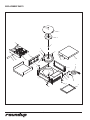
REPLACEMENT PARTS

13
P/N 1010881 Rev. F 03/12
REPLACEMENT PARTS (continued)
1 0010159 Filter Assy., Water Tank 1
2 7000370 Relay 1
3 4060374 Ground Lug, Copper 1
4 0011802 Pump/Tube Assy., 1
24VAC
5 7000391 A/C Line Isolator Board 1
6 7000237 Top Cover Assy. 1
(Incl. #41 & #42)
7 0011314 Steam Vent Assy. 1
8 0021131 Floor/Chassis Weld. 1
9 0012547 Access Cover Weld. 1
10 7000246 Generator, 230V 1
11 0300129 Stud, Cover Hold Down 1
12 040P138* Locknut, 1/2” 1
13 040K251 Strain Relief (Incl. #12) 1
14 05P2199* Spacer 2
15 0503431 Diffuser, Steam 1
16 4050229 Line Filter 1
17 0503433 Cover, Generator 1
18 0503434 Cover, End Housing 1
19 0503435 Retainer, Thermocouple 1
20 0503988 Spatula 1
21 0505733 Liner, Cavity 1
22 0504248 Bracket - Capacitor 1
23 0503472 Bracket, Hi-Limit 1
Support
24 0700453 Power Cord, CEE 7/7 1
(Mfg. No. 9100429)
0700437 Power Cord, IEC-309 1
(Mfg. No. 9100421)
25 00203-0091 Assy. Sub, MSFilter 1
26 100P967 Label, Marking 1
27 1001036 Label, Control Panel 1
28 2000203 Tube, Restrictor, 1/4” 1
29 0503429 Support, Generator 1
Upper.
30 7000849 Silicon Tube Kit, 1
Water Pump
31 2040106 Adapter, Tube/Hose 1
32 2040145 Elbow, Female, 1
1/8" x 1/4"
33 2040146 Tee, Female, 1
1/8" x 1/4"
34 7000693 Water Fitting Kit 1
(Incl. #28, 31, 32 & 33)
35 210K108 Foot, Rubber (4 Pack) 1
36 2100119 Handle, Spatula 1
37 4050180 Heat Sink 1
38 0011370 2” Leg Kit (Incl. #35) 4
39 2100118 Guard, Handle 1
40 0503536 Drip Pan 1
41 2100249 Guard, Knob 1
42 2100273 Knob 1
43 211P101 Clamp, Hose, 3/8" 1
44 211P195 Clamp, Hose 1
45 338P102* Bolt, Handle Mounting 1
46 7000446 Generator Tube, 2
3-5/8"
47 2100279 Guard, Spatula 1
(not shown)
48 300P102* Nut, Speed, “U”, #8-32 2
49 304P105* Nut, Hex, KEPS, 4
#4-40, Zinc
50 306P101* Nut, Hex, #6-32 2
51 306P105* Screw, Machine, 2
#6-32 x 1/2"
52 306P123* Screw, Machine, 2
#6-32 x 7/8”
53 306P130* Nut, Hex, KEPS, #6-32 2
54 306P134* Screw, Machine, 3
#6-32 x 3/8"
55 308P103* Screw, Machine, 6
#8-32 x 1/4"
56 4070078 Control Board, 1
Temperature/Timer,
24V, 50/60 Hz
57 308P105* Screw, Machine, 4
#8-32 x 1/2"
58 308P120* Screw, Machine, 4
#8-32 x 5/8" (sltrshd)
59 308P124* Screw, Machine, 1
#8-32 x 1/2" (one-way)
60 308P143* Nut, Hex, KEPS, #8-32 2
61 310P136* Screw, Machine, 4
#10-32 x 1-1/4"
(splanhd)
62 310P149* Screw, Machine, 2
#10-32 x 7/8"
63 7000136 Terminal Block, 3-Pole 1
64 325P170* Nut, Wing, 1/4-20 1
65 7000542 Rocker Switch, 1
Power On/Off 250V
66 4010166 Switch, Momentary 1
(Green)
4010190 Switch, Momentary 1
(White)
67 7000319 Transformer, 1
115-230/24/12V
68 7000135 Thermostat, Hi-Limit 1
69 4050214 Thermocouple, Type-K 1
70 406P107 Cable Tie (not shown) 3
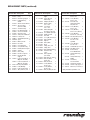
* Only available in quantities of 10.
Item Part No. Description Qty. Item Part No. Description Qty. Item Part No. Description Qty.

14
P/N 1010881 Rev. F 03/12
REPLACEMENT PARTS (continued)
43
31
32
33
23
55
28
46
4
49
43
46
30
30
30
READY
32
57
48
67
59
60
51
49
63
68
55
49
19
55
5
16
22
25
56
69
37
2
26
READY
READY
34
43
1
9
55

15
P/N 1010881 Rev. F 03/12
REPLACEMENT PARTS (continued)
1 0010159 Filter Assy., Water Tank 1
2 7000370 Relay 1
3 4060374 Ground Lug, Copper 1
4 0011802 Pump/Tube Assy., 1
24VAC
5 7000391 A/C Line Isolator Board 1
6 7000237 Top Cover Assy. 1
(Incl. #41 & #42)
7 0011314 Steam Vent Assy. 1
8 0021131 Floor/Chassis Weld. 1
9 0012547 Access Cover Weld. 1
10 7000246 Generator, 230V 1
11 0300129 Stud, Cover Hold Down 1
12 040P138* Locknut, 1/2” 1
13 040K251 Strain Relief (Incl. #12) 1
14 05P2199* Spacer 2
15 0503431 Diffuser, Steam 1
16 4050229 Line Filter 1
17 0503433 Cover, Generator 1
18 0503434 Cover, End Housing 1
19 0503435 Retainer, Thermocouple 1
20 0503988 Spatula 1
21 0505733 Liner, Cavity 1
22 0504248 Bracket - Capacitor 1
23 0503472 Bracket, Hi-Limit 1
Support
24 0700453 Power Cord, CEE 7/7 1
(Mfg. No. 9100429)
0700437 Power Cord, IEC-309 1
(Mfg. No. 9100421)
25 00203-0091 Assy. Sub, MSFilter 1
26 100P967 Label, Marking 1
27 1001036 Label, Control Panel 1
28 2000203 Tube, Restrictor, 1/4” 1
29 0503429 Support, Generator 1
Upper.
30 7000849 Silicon Tube Kit, 1
Water Pump
31 2040106 Adapter, Tube/Hose 1
32 2040145 Elbow, Female, 1
1/8" x 1/4"
33 2040146 Tee, Female, 1
1/8" x 1/4"
34 7000693 Water Fitting Kit 1
(Incl. #28, 31, 32 & 33)
35 210K108 Foot, Rubber (4 Pack) 1
36 2100119 Handle, Spatula 1
37 4050180 Heat Sink 1
38 0011370 2” Leg Kit (Incl. #35) 4
39 2100118 Guard, Handle 1
40 0503536 Drip Pan 1
41 2100249 Guard, Knob 1
42 2100273 Knob 1
43 211P101 Clamp, Hose, 3/8" 1
44 211P195 Clamp, Hose 1
45 338P102* Bolt, Handle Mounting 1
46 7000446 Generator Tube, 2
3-5/8"
47 2100279 Guard, Spatula 1
(not shown)
48 300P102* Nut, Speed, “U”, #8-32 2
49 304P105* Nut, Hex, KEPS, 4
#4-40, Zinc
50 306P101* Nut, Hex, #6-32 2
51 306P105* Screw, Machine, 2
#6-32 x 1/2"
52 306P123* Screw, Machine, 2
#6-32 x 7/8”
53 306P130* Nut, Hex, KEPS, #6-32 2
54 306P134* Screw, Machine, 3
#6-32 x 3/8"
55 308P103* Screw, Machine, 6
#8-32 x 1/4"
56 4070078 Control Board, 1
Temperature/Timer,
24V, 50/60 Hz
57 308P105* Screw, Machine, 4
#8-32 x 1/2"
58 308P120* Screw, Machine, 4
#8-32 x 5/8" (sltrshd)
59 308P124* Screw, Machine, 1
#8-32 x 1/2" (one-way)
60 308P143* Nut, Hex, KEPS, #8-32 2
61 310P136* Screw, Machine, 4
#10-32 x 1-1/4"
(splanhd)
62 310P149* Screw, Machine, 2
#10-32 x 7/8"
63 7000136 Terminal Block, 3-Pole 1
64 325P170* Nut, Wing, 1/4-20 1
65 7000542 Rocker Switch, 1
Power On/Off 250V
66 4010166 Switch, Momentary 1
(Green)
4010190 Switch, Momentary 1
(White)
67 7000319 Transformer, 1
115-230/24/12V
68 7000135 Thermostat, Hi-Limit 1
69 4050214 Thermocouple, Type-K 1
70 406P107 Cable Tie (not shown) 3
* Only available in quantities of 10.
Item Part No. Description Qty. Item Part No. Description Qty. Item Part No. Description Qty.

LIMITED WARRANTY
Equipment manufactured by Roundup Food Equipment Division of A.J. Antunes & Co. has been constructed of the finest materi-
als available and manufactured to high quality standards. These units are warranted to be free from electrical and mechanical
defects for a period of one (1) year from date of purchase under normal use and service, and when installed in accordance with
manufacturer’s recommendations. To insure continued operation of the units, follow the maintenance procedures outlined in the
Owner’s Manual. During the first 12 months, electro-mechanical parts, non-overtime labor, and travel expenses up to 2 hours (100
miles/160 km), round trip from the nearest Authorized Service Center are covered.
1. This warranty does not cover cost of installation, defects caused by improper storage or handling prior to placing of the Equipment.
This warranty does not cover overtime charges or work done by unauthorized service agencies or personnel. This warranty does
not cover normal maintenance, calibration, or regular adjustments as specified in operating and maintenance instructions of this
manual, and/or labor involved in moving adjacent objects to gain access to the equipment. This warranty does not cover consum-
able/wear items. This warranty does not cover damage to the Load Cell or Load Cell Assembly due to abuse, misuse, dropping of
unit/shock loads or exceeding maximum weight capacity (4 lbs). This warranty does not cover water contamination problems such
as foreign material in water lines or inside solenoid valves. It does not cover water pressure problems or failures resulting from
improper/incorrect voltage supply. This warranty does not cover Travel Time & Mileage in excess of 2 hours (100 miles/160 km) round
trip from the nearest authorized service agency.
2. Roundup reserves the right to make changes in design or add any improvements on any product. The right is always reserved to
modify equipment because of factors beyond our control and government regulations. Changes to update equipment do not con-
stitute a warranty charge.
3.
If shipment is damaged in transit, the purchaser should make a claim directly upon the carrier. Careful inspection should be made of the
shipment as soon as it arrives and visible damage should be noted upon the carrier’s receipt. Damage should be reported to the carrier.
This damage is not covered under this warranty.
4. Warranty charges do not include freight or foreign, excise, municipal or other sales or use taxes. All such freight and taxes are the
responsibility of the purchaser.
5. THIS WARRANTY IS EXCLUSIVE AND IS IN LIEU OF ALL OTHER WARRANTIES, EXPRESSED OR IMPLIED, INCLUDING ANY IMPLIED
WARRANTY OR MERCHANTABILITY OR FITNESS FOR A PARTICULAR PURPOSE, EACH OF WHICH IS HEREBY EXPRESSLY DIS-
CLAIMED. THE REMEDIES DESCRIBED ABOVE ARE EXCLUSIVE AND IN NO EVENT SHALL ROUNDUP BE LIABLE FOR SPECIAL CON-
SEQUENTIAL OR INCIDENTAL DAMAGES FOR THE BREACH OR DELAY IN PERFORMANCE OF THIS WARRANTY.
-
 1
1
-
 2
2
-
 3
3
-
 4
4
-
 5
5
-
 6
6
-
 7
7
-
 8
8
-
 9
9
-
 10
10
-
 11
11
-
 12
12
-
 13
13
-
 14
14
-
 15
15
-
 16
16


A.J.Antunes roundup MS-150 Owner's manual
- Type
- Owner's manual
- This manual is also suitable for
Ask a question and I''ll find the answer in the document
Finding information in a document is now easier with AI
Related papers

Other documents
-
Game Of Bricks 40485 User manual
-
Roundup 9100435 Owner's manual
-
Antunes, AJ roundup MS-150 Owner's manual
-
-
-
-
-
-
-