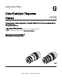
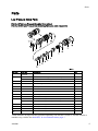
Graco 332454B is a set of parts for repairing and disassembling color/catalyst dispense valves used in ProMix® PD2K Electronic Proportioning Systems with the color change option. These valves are designed to dispense color, catalyst, and solvent in professional applications.
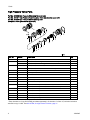
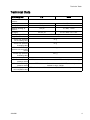
The kit includes parts for both low-pressure (300 psi maximum working pressure) and high-pressure (1500 psi maximum working pressure) valves, as well as o-rings and other small parts. The valves can be used with a variety of fluids with viscosities ranging from 20 to 5000 centipoise.
Graco 332454B is a set of parts for repairing and disassembling color/catalyst dispense valves used in ProMix® PD2K Electronic Proportioning Systems with the color change option. These valves are designed to dispense color, catalyst, and solvent in professional applications.
The kit includes parts for both low-pressure (300 psi maximum working pressure) and high-pressure (1500 psi maximum working pressure) valves, as well as o-rings and other small parts. The valves can be used with a variety of fluids with viscosities ranging from 20 to 5000 centipoise.


-
 1
1
-
 2
2
-
 3
3
-
 4
4
-
 5
5
-
 6
6
-
 7
7
-
 8
8
-
 9
9
-
 10
10


Graco 332454B User manual
- Type
- User manual
- This manual is also suitable for
Graco 332454B is a set of parts for repairing and disassembling color/catalyst dispense valves used in ProMix® PD2K Electronic Proportioning Systems with the color change option. These valves are designed to dispense color, catalyst, and solvent in professional applications.
The kit includes parts for both low-pressure (300 psi maximum working pressure) and high-pressure (1500 psi maximum working pressure) valves, as well as o-rings and other small parts. The valves can be used with a variety of fluids with viscosities ranging from 20 to 5000 centipoise.
Ask a question and I''ll find the answer in the document
Finding information in a document is now easier with AI
Related papers
-
Graco 406875A, 24F249 Carbide Seat Kit User manual
-
-
-
-
-
-
-
-
-
Graco 334558B User manual