Page is loading ...

Installation Guide| Eclipse HX-Matrix
Page 1
Eclipse HX Matrix
An installation guide
for the Eclipse HX
intercom matrix
Part Number:399G303 Rev A
Date: 14 June 2019
Installation
Guide

Installation Guide| Eclipse HX Matrix
Page 2
Document Reference
Eclipse HX Matrix Installation Guide
Product Number: 399G303 Revision: A
Legal Disclaimers
Copyright © 2019 HME Clear-Com Ltd
All rights reserved.
Clear-Com, the Clear-Com logo, and Clear-Com Concert are trademarks or
registered trademarks of HM Electronics, Inc.
The software described in this document is furnished under a license agreement
and may be used only in accordance with the terms of the agreement.
The product described in this document is distributed under licenses restricting
its use, copying, distribution, and decompilation/reverse engineering. No part of
this document may be reproduced in any form by any means without prior
written authorization of Clear-Com, an HME Company.
Clear-Com Offices are located in California, USA; Cambridge, UK; Dubai, UAE,
Montreal, Canada; and Beijing, China. Specific addresses and contact
information can be found on Clear-Com’s corporate website:
www.clearcom.com
Clear-Com Contacts
Americas and Asia-Pacific Headquarters
California, United States
Tel: +1.510.337.6600
Email: CustomerServicesUS@clearcom.com
Europe, Middle East, and Africa Headquarters
Cambridge, United Kingdom
Tel: +44 1223 815000
Email: SalesSupportEMEA@clearcom.com
Canada Office
Quebec , Canada
Tel: +1 (450) 653-9669
China Office
Beijing Representative Office
Beijing, P.R.China
Tel: +8610 65811360/65815577

Installation Guide| Eclipse HX Matrix
Page 3
Table of Contents
1 Introduction ...................................................................................... 6
1.1 Summary of Chapters ...................................................................... 7
1.2 Further information ......................................................................... 7
2 Installation Overview ........................................................................ 8
2.1 Before installing the system ............................................................. 8
2.1.1 Check the shipment ................................................................... 8
2.1.2 Select locations for the system components .................................. 9
2.1.3 Determine cabling and wiring scheme requirements ...................... 9
2.2 Installing the Eclipse HX system ..................................................... 11
2.2.1 Installing the matrix in a 19” rack ............................................. 11
2.2.2 System limits .......................................................................... 12
2.2.3 Installing the cabling ............................................................... 13
2.2.4 Connecting the other system components to the matrix ............... 13
2.2.5 Connecting to mains AC power .................................................. 13
2.3 After installing the Eclipse HX system .............................................. 14
2.3.1 Configuring the system with EHX software .................................. 14
2.3.2 Minimum PC requirements (for EHX software) ............................. 15
2.3.3 Recommended PC requirements (for EHX software) ..................... 16
2.3.4 Checking the installed system ................................................... 16
3 Locating System Components .......................................................... 19
3.1 Locating Eclipse HX matrices .......................................................... 19
3.1.1 Locating the Eclipse HX-Omega, Eclipse HX-Median and Eclipse HX-
Delta 20
3.1.2 Locating the Eclipse HX-PiCo ..................................................... 21
3.2 Locating interface frame(s) and power supplies ................................ 21
3.2.1 IMF-3 interface frame .............................................................. 21
3.2.2 IMF-102 interface frame ........................................................... 23
3.3 Locating user panels...................................................................... 23
3.4 Locating the external computer for EHX ........................................... 23
4 Powering System Components ........................................................ 25
4.1 Powering matrices ......................................................................... 25
4.1.1 Eclipse HX-Omega and Eclipse HX-Median .................................. 26
4.1.2 Eclipse HX-Delta ...................................................................... 26
4.1.3 Eclipse HX-PiCo ....................................................................... 26
4.2 Powering user panels .................................................................... 26
4.2.1 V-Series panels ....................................................................... 26
4.2.2 I-Series panels ........................................................................ 27
4.3 Powering interface frames .............................................................. 27
4.3.1 IMF-3 ..................................................................................... 27

Installation Guide| Eclipse HX Matrix
Page 4
4.3.2 IMF-102 ................................................................................. 28
4.3.3 Current capacities and consumption .......................................... 29
5 Wiring System Components ............................................................. 30
5.1 Using RJ-45 connectors ................................................................. 30
5.1.1 Cabling standards .................................................................... 31
5.1.2 Recommended cables, connectors and wiring tools ...................... 32
5.1.3 Installing RJ-45 Connectors ...................................................... 32
5.2 Connecting the matrix to a PC running EHX ...................................... 34
5.2.1 Ethernet connection to the PC ................................................... 34
5.2.2 Serial connection to the PC ....................................................... 34
5.3 Connecting the matrix to an Ethernet network .................................. 37
5.4 Connecting the matrix to a PC running Dynam-EC ............................. 38
5.4.1 LMC-64 interface card .............................................................. 38
5.5 Connecting the matrix to user panels .............................................. 38
5.5.1 4-Pair analog wiring ................................................................. 38
5.6 General Purpose Outputs (GPOs) .................................................... 39
5.7 General Purpose Inputs (GPIs) ....................................................... 43
5.7.1 Modes for General Purpose Inputs (GPIs) ................................... 44
5.8 E & M signalling with an E-QUE E1 / T1 interface card ....................... 47
5.8.1 Example: Ship-to-shore satellite system .................................... 47
5.8.2 Enabling E & M signaling on the E-QUE card ............................... 48
5.8.3 Using the GPIs / GPOs to trigger actions .................................... 49
5.9 Connecting the matrix to an external alarm ...................................... 51
5.9.1 Connecting to the alarm outputs of the PSU-101 power supply ..... 51
5.10 Connecting to a four-wire audio device ......................................... 52
5.11 Connecting to interface modules .................................................. 52
5.11.1 Wiring schemes for the FOR-22 interface module ...................... 54
5.11.2 Wiring schemes for the CCI-22 interface module ...................... 55
5.11.3 Wiring schemes for TEL-14 interface modules .......................... 58
5.11.4 Wiring scheme for the RLY-6 interface module ......................... 63
5.11.5 Wiring schemes for a GPI-6 Interface module........................... 66
6 Connecting Matrices ........................................................................ 70
6.1 Intelligent linking .......................................................................... 70
6.1.1 Intelligent linking with trunk lines .............................................. 70
6.1.2 Serial port to serial port linking ................................................. 71
6.2 Linking Eclipse HX-Pico matrices with the PiCo-Link ........................... 73
6.3 Tie-line (audio only) linking ............................................................ 74
6.4 E1 / T1 linking .............................................................................. 74
6.4.1 E1 trunk connections ............................................................... 75
6.4.2 T1 trunking............................................................................. 78


Installation Guide| Eclipse HX Matrix
Page 6
1 Introduction
The Eclipse HX-Matrix Installation Guide describes the steps required to
install and configure an Eclipse HX matrix system. The Eclipse HX system is a
digital point-to-point intercom platform, designed to seamlessly integrate your
entire intercom infrastructure (digital, wireless, IP-based and analog intercom
systems). The system comprises matrices, interface cards and modules, user
panels and interface frames.
The system is configured and managed using the highly intuitive EHX software.
This guide:
• Provides information about placing, powering, and wiring the hardware
system components.
• Defines many of the concepts used in the system.
Note: For more information about EHX, see your EHX documentation, including EHX
Help (integrated with your software).
Servicing instructions are for use by qualified personnel only.
To reduce the risk of electric shock, do not perform any
servicing other than that described by this guide, unless
qualified to do so. Refer all servicing to qualified service
personnel.

Installation Guide| Eclipse HX Matrix
Page 7
1.1 Summary of Chapters
Chapter
Summary
1 Installation Overview
Provides a step-by-step installation guide for the
components of the Eclipse matrix system, as
received from the factory.
2 Locating System
Components
Describes the environmental / location
requirements for the matrix system components.
Includes a summary of component sizes.
3 Powering System
Components
Provides guidelines for providing AC power to the
system and for planning the powering of interface
frames.
4 Wiring System
Components
Provides an overview of the various wiring systems
for connecting panels and interfaces to the matrix.
This chapter contains reference information to help
you wire all connectors in the Eclipse HX system.
Information on internal jumpers, adjustments, and
device specifications can be found in the individual
documentation for each component.
5 Connecting
Provides information on connecting different
matrices together.
Table 1: Summary of Chapters
1.2 Further information
For more information about any of the Eclipse HX system components (devices) referenced
in this guide (including matrices, interface cards, interface modules and software), see the
specific documentation for that device or software.
Eclipse HX documentation is available from:
• Your product DVD-ROM.
• The Clear-Com website (http://www.clearcom.com/product/digital-matrix).
For sales information, see your Clear-Com sales representative. For contact information, see
Page 2 of this guide.

Installation Guide| Eclipse HX-Matrix
Page 8
2 Installation Overview
This chapter provides a basic overview of the installation process for an Eclipse HX system.
This system comprises:
• An Eclipse HX matrix (either the 6RU Eclipse HX-Median or Eclipse
HX-Omega or the 3RU Eclipse HX-Delta matrices, or the 1RU Eclipse
HX-PiCo matrix).
• An external computer (PC), which hosts the Eclipse HX (EHX)
configuration software.
• Interface modules, which enable connections with a wide range of
intercom systems, from analog and digital intercom systems, to wireless
systems and telephone networks.
• Interface frames, which are used to host interface modules.
• User Panels, from either the V-Series or I-Series families of user
panels.
Note: This chapter is designed for general guidance only. For more detailed
information about individual system components, and how to connect them
(including wiring schemes), see the rest of this guide.
2.1 Before installing the system
2.1.1 Check the shipment
When you receive your Eclipse HX matrix system components:
• Inspect the boxes for shipping damage. Report any shipping damage to
the carrier.
Note: The Eclipse matrix system distributor is not responsible for
shipping damage.
• Check that every item on the packing list has been received.
• Check that auxiliary options have been fitted to system components (such
as V-Series panels and I-Series panels).
Note: Auxiliary options may also include interface cards (sometimes
called expansion cards or intercom panels) for the Eclipse HX-
Omega, Eclipse HX-Median and Eclipse HX-Delta matrices . The
names of interface cards are displayed on the front and rear
cards in each set.
• Save all packing materials (boxes, Styrofoam). If any item has been
shipped in error, is malfunctioning, or requires warranty service, use the
original packing materials to return that item to Clear-Com.

Installation Guide| Eclipse HX Matrix
Page 9
2.1.2 Select locations for the system components
Select locations for the Eclipse HX matrix, interface cards, interface modules,
user panels, PC, and any other system components.
The Eclipse HX matrix is the central connecting point of the system. All other devices are
connected, either directly or indirectly, to the matrix, and this central role must be accounted
for in your system topography.
Note: For additional information about locating the Eclipse HX matrix system, see 3
Locating System Components.
2.1.3 Determine cabling and wiring scheme requirements
The Eclipse HX system requires shielded category-5 (CAT5) cable with RJ-45
connectors. All Eclipse matrices have built-in RJ-45 connectors.
Wiring schemes
Different wiring schemes are required, depending on the intercom device / system
component that is being connected.
For example:
System
component
Connections
External computer
(PC) for EHX
The Eclipse HX configuration software runs on an external computer
(PC). The computer is normally connected to the matrix using the
LAN1 connector (a standard RJ-45 Ethernet connector).
For Eclipse HX-Omega, Eclipse HX-Median and Eclipse HX-PiCo, a
ferrite core must be added to the socket end of each Ethernet cable
to comply with European EMC standards. A suitable ferrite core is
Würth Electronik part: 74271132.
Shielded CAT5 cable is recommended for Electro Magnetic
Compliance in EC countries.
Note: LAN1 is the default connector on the matrix. The LAN2
connector (which is also a standard RJ-45 Ethernet
connector) is unconfigured when it leaves the factory and
must be enabled in EHX before it can be used.
Tip: Connecting through an Ethernet network enables one
or more matrices to be controlled through one or more
computers on a network. You can also use the supplied DB-
9 cable or a commercially available shielded RS-232 cable.
For more information, see For more information, see 5.2
Connecting the matrix to a PC running EHX.

Installation Guide| Eclipse HX Matrix
Page 10
Note:The Eclipse HX-Pico uses a special null modem DB9 to
3.5 TRS. The HX-Median / HX-Omega /HX-Delta CPU card
uses a straight serial cable.
If the EHX computer does not have a serial port, but only
provides USB connectors, adapters are available from
computer parts suppliers. However, you will be required to
install drivers for USB-to-serial port connections.
Important note: Because of compatibility issues with some
products, Clear-Com does not recommend the use of USB-
to-serial port connections.
User panels (V-
Series and I-
Series user
panels)
An analog connection, using shielded CAT5 4-twisted pair
cables with RJ-45 connectors, is the most common way of
connecting V-Series user panels and I-Series panels to the
matrix.
You can use the following alternative methods for
connecting V-Series panels:
A digital connection, using the AES-6 digital interface
module. Coaxial cable is required to connect panels to the
AES-6CX rear card.
An IP-based connection, using the IVC-32 interface card
(fitted to an HX-Median, HX-Omega or HX-Delta matrix).
The IVC-32 interface card allows the Eclipse HX matrix to
connect to IP enabled V-Series panels over existing WAN /
LAN Ethernet cabling infrastructure. V-Series panels can
also optionally support up to two additional IP channels. For
more information, see the V-Series Panel User Guide.
The IVC-32 card can add IP connections through an
Ethernet switch / router linked to the Ethernet network. For
more information about the IVC-32 card, see the:
Eclipse HX-Omega, Eclipse HX-Median or Eclipse HX-
Delta User Guide.
Note: For each user panel, additional connector wiring may
be required, depending on the options and accessories
installed. See 5 Wiring System Components in this guide,
and the user manual for your panel.
Interface
modules
Interface modules are connected to the matrix using:
• Particular wiring schemes (for each module type) on
the DB-9 connectors on the rear of the associated
interface frame (IMF-3).
• Shielded CAT5 4-twisted pair cables with RJ-45
connectors.

Installation Guide| Eclipse HX Matrix
Page 11
The RLY-6 and GPI-6 interface modules are connected
directly using an RJ-45 connector on the rear of the matrix
to the appropriate interface input connector on the interface
frame (IMF-3).
For more information, see 5.11 Connecting to interface
modules.
External alarm
Eclipse HX matrices have built-in fault alarm systems.
If you want to use an additional remote alarm, relay
contacts are available on the rear panel of the matrix.
If you want to add an external alarm condition to the matrix
alarm system, the same connector on the rear panel alarm
I/O will permit an external contact closure to be connected
to the matrix alarm system.
Shielded cable is recommended for Electro Magnetic
Compliance in EC countries.
Table 2: Wiring schemes
Note: For more information about RJ-45 connectors and their installation, see: 3
Locating System Components.
For detailed information about wiring schemes, see 5 Wiring System
Components.
For more detailed information about the range of interface cards that can be
installed to 6RU matrices, see either:
• The Eclipse HX-Omega User Guide.
• The Eclipse HX-Median User Guide.
• The Eclipse HX-Delta User Guide.
2.2 Installing the Eclipse HX system
2.2.1 Installing the matrix in a 19” rack
Install the matrix in a standard Electronics Industry Association 19-inch wide
(48.26 cm) equipment rack. Clear-Com recommends installing the matrix to the
center portion of the rack, allowing easy access to the connectors on the rear
of the matrix.
Because of the large number of cables connected to the matrix, you should also
plan for the dressing of cables.
Environmental information

Installation Guide| Eclipse HX Matrix
Page 12
The matrix requires adequate ventilation. Leave at least 2 inches (50.8 mm) of
clearance on all sides of the matrix to ensure proper airflow. Do not block
ventilation vents.
Check the position of the circuit cards (CPU cards and interface cards), power
supplies, and rear connector panels.
Note: For detailed information about installing a particular matrix or interface frame in
the rack, see the appropriate guide in the Eclipse HX documentation set. For
matrices, see the:
• Eclipse HX-Omega User Guide.
• Eclipse HX-Median User Guide.
• Eclipse HX-Delta User Guide.
• Eclipse HX-PiCo User Guide.
For interface frames, see your IMF-3 or IMF-102 documentation.
2.2.2 System limits
The following limits apply when installing cards in an Omega, Median or Delta
matrix:
• IVC-32, E-Que and LMC-64 cards are high-power devices, and you can
only install a total of four of these cards in an Eclipse Median or Delta
frame. If more high-power cards are installed, the CPU only services the
first four cards (based on lower slot numbers). In this case, a warning
message is sent to the event log every 10 minutes. See Error! Reference s
ource not found. Error! Reference source not found..
• In an Eclipse Omega frame that is fitted with a Power-One PSU, you can
install up to a total of six high-power cards. In this case, you are
recommended to install a fan tray.However, you cannort install more
than four antenna/splitter E-Que cards, or more than four E-Que cards
with EM Signalling enabled. For more information about the Power-One
PSU, including part number see 5.7 Power Supplies in the Eclipse HX
Omega User Guide.
This is summarized in the table below:
Card
Maximum number
with Power-One
PSU (720379Z)
Maximum number
with other PSU
IVC-32
6
4
LMC-64
6
4
E-Que antenna/splitter
4
4
E-Que with EM signalling
enabled
4
4
E-Que other
6
4

Installation Guide| Eclipse HX Matrix
Page 13
If you attempt to add a high-power card to a matrix that already has the
maximum number installed, a warning displays in EHX software.
2.2.3 Installing the cabling
Install the intercom cables between the Eclipse HX matrix and the other system
components (user panels and interface frames).
Clear-Com recommends that you route cables before wiring the connectors to
the cables.
Note: For more information about routing cables, see 3 Locating System
Components.
2.2.4 Connecting the other system components to the matrix
Connect the system components / devices (such as the external computer for
EHX, interface frames and modules, and external alarms) to the matrix.
For a wiring scheme / connection overview, see 2.1.3 Determine cabling and
wiring scheme requirements > Wiring schemes above.
Note: For detailed information about wiring schemes, see 5 Wiring System
Components.
2.2.5 Connecting to mains AC power
Eclipse HX matrices and interface frames (IMF-3)
Eclipse HX matrices have two separate AC power connectors for two separate
power supplies in the system. Either power supply will completely power a
system, providing 100% power redundancy. If the two power supplies are
connected to different AC power sources and one of the power supplies loses
power, the other will continue to operate the system.
AC voltage for the matrices and the PSU-101 can be 100 - 240 VAC without
any switching or fuse changes.
Each component of the Eclipse HX system requires AC power except for the
IMF-3 and some interface modules. The IMF-3 requires an external power
supply. The XP-type expansion panels receive power from the panels to which
they are connected.
If you are installing an IMF-3, install the DC power cables that connect the
power supply to the matrix. For the matrix and each connected component,
install and connect the mains AC power cables.
Note: For further information, see 4 Powering System Components.
2.2.5.1 V-Series panels
Each V-Series panel has an external power supply and a removable cradle to
hold the external power supply.

Installation Guide| Eclipse HX Matrix
Page 14
AC voltage for these panels can be 100 - 240 VAC without any switching or
fuse changes.
2.2.5.2 I-Series panels
I-Series panels have internal power supplies, with removable AC power cords.
The power supplies are universal, operating over a voltage range of 90 - 245
VAC and 50 - 60 Hz. The maximum dissipation is 40 W.
Note: Each panel must be plugged into an AC source at its location.
Only connect power supply to earthed supply sockets. Ensure
that the power supply is routed to avoid sharp bends, hot
surfaces, pinches and abrasion. Refer all servicing to qualified
service personnel.
For more safety guidance, see the Safety Instructions supplied
with this product
.
2.3 After installing the Eclipse HX system
2.3.1 Configuring the system with EHX software
The Eclipse HX (EHX) configuration software controls the operation of the
connected audio devices by sending signals to the CPU and interface cards in the
matrix, which then relay the signals to connected audio devices and systems.
Configurations (the operating parameters of complete system setups) are
created in EHX.
Up to four complete system configurations can be stored in the CPU card of the
Eclipse HX-Median, Eclipse HX-Omega, Eclipse HX-Delta or the CPU of the HX-
PiCO. These configurations can be retrieved and activated on the matrix when
required.
The external PC that hosts the EHX software can store an almost unlimited
number of complete system configurations (the number is only limited by the
available memory space on the PC). You can download the configurations to the
matrix as required.
When running EHX on Windows operating systems, the client and server can run
on separate machines connected over a network. You can use EHX to perform a
wide range of configuration tasks, including:
• Assigning labels (names) to ports and user panels.
• Creating point-to-point and fixed group (partyline) communications
between connected audio devices.
• Enabling, limiting or disabling features of any connected user panel or
card.
• Configuring connections between matrices .
Note: The above list is not definitive. For more information about the capabilities of
EHX, see EHX Help.

Installation Guide| Eclipse HX Matrix
Page 15
2.3.2 Minimum PC requirements (for EHX software)
Specification
Description / Value
Processor
1 GHz
Memory
1GB RAM
Hard disk
1GB minimum 32 bit, 2GB minimum 64 bit.
Input devices
CD-ROM drive
Display resolution
SVGA
User entry
Keyboard, Mouse
Ports
2 serial ports and/or network IEEE 802.3 Ethernet
card
Network
IEEE 802.3 Ethernet card
Operating systems
EHX 8.5.1 runs on the following versions of
Windows:
• Microsoft Windows 7 (32-bit and 64-bit).
• Microsoft Windows 8.1 (32-bit and 64-bit).
• Microsoft Windows 10 (32-bit and 64-bit).
• Microsoft Windows Server 2008 R2 (64-bit).
• Microsoft Windows Server 2012 R2 (64-bit).
Operation on other platforms is no longer supported.
Table 3: Minimum PC requirements

Installation Guide| Eclipse HX Matrix
Page 16
2.3.3 Recommended PC requirements (for EHX software)
Specification
Description / Value
Processor
2GHz or greater for a client.
As many cores as possible for a server.
Memory
2GB for client 32 bit.
4GB for client 64 bit.
3GB for server 32 bit.
4GB+ for server 64 bit.
Free space
1GB minimum 32 bit.
2GB minimum 64 bit.
Display resolution
1600 x 1200
Operating systems
EHX 8.5.1 runs on the following versions of
Windows:
• Microsoft Windows 7 (32-bit and 64-bit).
• Microsoft Windows 8.1 (32-bit and 64-bit).
• Microsoft Windows 10 (32-bit and 64-bit).
• Microsoft Windows Server 2008 R2 (64-bit).
• Microsoft Windows Server 2012 R2 (64-bit).
Operation on other platforms is no longer supported.
Table 4: Recommended PC requirements
2.3.4 Checking the installed system
After configuring the Eclipse HX system, check that every system component is
functioning correctly, including all:
• Control inputs, outputs and audio paths.
• Connections with connected external devices, such as interface modules
and User Panels
• Software functions, such as partylines, ISO and IFB functionality.
To assist with testing, the Eclipse HX system is delivered with a fully functional
default EHX configuration. You can tailor the configuration, using EHX software,
to meet the requirements of your particular installation.
Note: Because each installation is different, it is beyond the scope of this guide to
outline in detail all the checks that you must carry out.
Checking the matrix
Eclipse HX-Omega, HX-Median and HX-Delta

Installation Guide| Eclipse HX Matrix
Page 17
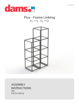
The LEDs on the front of the CPU card indicate its operational status:
Figure 1: CPU card LEDs
RESET
+5V
+3.3V
OK
IPC
MASTER
LAN A
LAN B
IN SYNC
SI
CONFIG
ENG
RESET
The two power supplies are
lit green to indicate that they
are working.
Dot matrix display indicates
which of the four stored
configurations is currently
operational. The configuration
number displays for a short
time after power up (2s) or
when the configuration is
selected.
OK LED flashes green
(1:1 1Hz) to indicate that the
CPU software is working.
Master LED is lit green on
whichever CPU card is
currently serving as master.
IPC (Interprocessor
communication) LED is lit
green to indicate that the two
CPU cards (primary and
backup) are exchanging
information.
LAN LEDs (A and B) are lit
green to indicate connection
with LAN port(s).
When multiple Eclipse HX
matrices are connected
together, the IN SYNC LED is
lit to indicate that the matrices
are connected and
synchronized.
SI LED flashes green (1:1 1Hz)
to indicate communications
activity.

Installation Guide| Eclipse HX Matrix
Page 18
Note: For more information about the lights and controls on the CPU card, see either:
• The Eclipse HX-Omega User Guide.
• The Eclipse HX-Median User Guide.
• The Eclipse HX-Delta User Guide
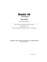
Eclipse HX-PiCo
The LEDs on the front of the matrix indicate its operational status:
Figure 2: Eclipse HX-PiCo LEDs
Note: For more information about the lights and controls on the front of the Eclipse
HX-PiCo, see the Eclipse HX-PiCo User Guide.
One of the four configuration LEDs is
lit to indicate which configuration is
currently operational.
LAN Link LED
flashes green to
indicate an
operational LAN
connection.
RX LED flashes
yellow to indicate
when data is being
received.
PSU Alarm LEDs (1 and 2).
(Not lit during normal
operation).
OK LED flashes green (1:1 1Hz)
to indicate that the CPU software
is working.

Installation Guide| Eclipse HX-Matrix
Page 19
3 Locating System Components
This chapter provides help with deploying (locating and arranging) the principal
components of your Eclipse HX system, including:
• Eclipse HX matrices (Eclipse HX-Omega, Eclipse HX-Median, Eclipse HX-
Delta and Eclipse HX-PiCo).
• An external computer (for the EHX configuration software).
• Interface frame(s) (the IMF-3 and IMF-102), which host interface
modules.
• User panels (either V-Series or I-Series panels).
• Power supplies.
Note: For an overview of the entire installation process, see 2 Installation Overview.
3.1 Locating Eclipse HX matrices
The Eclipse HX matrices comprise the 6RU Eclipse HX-Omega and Eclipse HX-
Median, the 3RU Eclipse HX-Delta and the 1RU Eclipse HX-PiCo.
The Eclipse HX matrix is the central connecting point of the system. All other
devices are connected, either directly or indirectly, to the matrix, and this
central role must be accounted for in your deployment planning and cabling
topography.
To allow easy access to connectors, ensure that you install the matrix to a
central position in the standard Electronics Industry Association 19-inch
wide (48.26 cm) rack. Because of the potentially large number of cables that
may be connected to the matrix, some planning may also be necessary for
dressing the cables.
Note: A rack unit (1RU) refers to a standardized unit of space in an Electronics
Industry Association equipment rack. One rack unit is 1.75 inches high and 19
inches wide (44.45 mm by 482.6 mm). Each increasing rack unit (1RU) adds
1h.75 inches to the area vertically, while staying at 19 inches horizontally.

Installation Guide| Eclipse HX Matrix
Page 20
3.1.1 Locating the Eclipse HX-Omega, Eclipse HX-Median and
Eclipse HX-Delta
The Eclipse HX-Omega and Eclipse HX-Median matrices each require six
vertical rack units (6RU) (10.5 inches or 267 mm) in a standard Electronics
Industry Association 19-inch wide (48.26 cm) rack. The Eclipse HX-Delta matrix
requires three vertical rack units (3RU) (5.25 inches or 134 mm) in the same
19-inch rack.
3.1.1.1 Cooling the Omega / Median matrix
Each matrix has two power supplies (one for redundancy). A modular
removable alarm module fitted beneath the two power supplies has two fans
that deliver forced air cooling. The primary fan runs continuously. If the
temperature in the matrix exceeds a set threshold and extra cooling is required,
a secondary fan switches on to increase the air flow in the matrix.
The fan-on alarm LED on the front of the alarm module illuminates red to
indicate that the secondary fan is on. The red fan-fail alarm LED illuminates
when either fan stops rotating correctly. These alarm LEDs allow the system
operator to identify and correct the alarm conditions.
For more information, see the:
• Eclipse HX-Omega User Guide.
• Eclipse HX-Median User Guide
Environmental information:
• The air flow through a 6RU matrix from the bottom to the top must be
unimpeded.
• If other equipment is mounted above and below the matrix that impedes
the air flow through the matrix, it will be necessary to leave 1 RU of
empty space above and below the matrix to prevent over-heating.
• If the matrix is mounted in a portable case this air flow must not be
impeded.
Cooling the Delta matrix
Each matrix has two external power supplies (one for redundancy). A modular
removable fan/alarm module at the front of the unit has two fans that deliver
forced air cooling. Both fans run continuously, but as the temperature increases,
their speed increases to boost the air flow in the matrix.
The fan fail alarm LEDs illuminate if the corresponding fan stops rotating
correctly. These alarm LEDs allow the system operator to identify and correct
the alarm conditions.
For more information, see the
• Eclipse HX-Delta User Guide
Environmental information:
/