12 DKRCC.PS.RQ0.B7.02 /520H8832 © Danfoss A/S (AC-MCI / sw), 2015-02
Manual Superheat Controller EIM 336
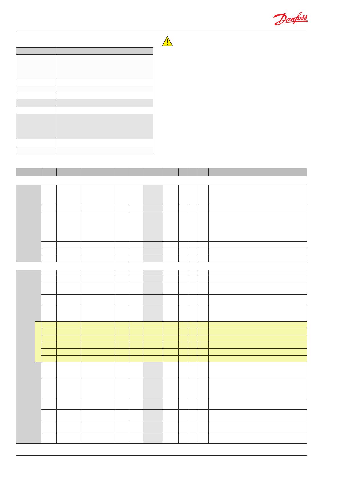
Parameter list
Row text Explanation
PNU
The Parameter Number in the EIM 336 controller.
All parameters are addressed as holding register.
The Modbus PDU address corresponds to PNU-1.
If no translation table is used, this is the register
number in modbus.
Min. Minimum value
Def. Factory default value
Max. Maximum value
e2 Is the value stored in EEPROM
W Is writing to the register possible
*10
The scaling of the parameter. All values are read/
written as integers over modbus. Parameters
need to be scaled, these are marked with a
checkmark. This means that 0.1 is sent as 1 over
modbus, 1.0 is sent as 10 etc.
Symbolic name The name of the parameter
Description Short parameter description
Group PNU Parameter Symbolic name Min. Max. Default Units e2 W *10 Description
Control
Regulation
Control
117 r12 Main switch 0 1 0
ü
Start/stop of regulation. With this setting the
regulation can be started and stopped. This can
also be accomplished with the external hardware
main switch. See also appendix 1
2075 o18 Manl control 0 1 0
ü
0 = Superheat control, 1= Manual control
2064 o45 Manual OD 0
100 /
480
0
% /
step
ü
Manual opening degree for manual control .
Used when the o18 Manual Control is set to 1.
0%/0 step = fully closed,
100%/480 step = fully open.
% is chosen by default.
See PNU 64309 for changing to step.
3017 n15 Startup time 0 1000 0 s
ü ü
Time for startup state (in seconds)
3012 n17 Startup OD 0 100 0 %
ü ü
Opening degree during startup state
64308 OOD OD while OFF 0 100 0 %
ü ü
Opening degree during O state
Regulation
Super Heat
Control
3015 n09 Max. superheat 2 20 16 K
ü ü ü
Maximum superheat reference setting
3021 n10 Min. superheat 1 20 4 K
ü ü ü
Minimum superheat reference setting
3025 n20 KpT0 -1 20 -1
ü ü ü
Pressure feedback gain
Automatic = -1, OFF = 0 , Fixed = 1 and above
3027 n22 SH close 0 16 0.5 K
ü ü ü
Superheat close level. If the superheat goes below
this value, the valve will close faster
3103 TSH Tn SH 10 1800 600
ü ü
Tn integration time for the superheat control.
Lower value give fast regulation response.
Very low value give the risk of unstable regulation.
For Danfoss only!
3105 SHL SH Low 3 20 6 K
ü ü ü
Superheat low setting for non-linear control
3106 SHH SH High 8 40 16 K
ü ü ü
Superheat high setting for non-linear control
3107 GaH Gain High 0.5 10 1
ü ü ü
Expected gain at SH high for non-linear control
3108 GaL Gain Low 0.1 50 12.5
ü ü ü
Expected gain at SH low for non-linear control
3109 TaH Tau High 10 600 45
ü ü
Expected tau at SH high for non-linear control
3110 TaL Tau Low 10 600 110
ü ü
Expected tau at SH low for non-linear control
3111 Aph Alpha 15 600 130
ü ü
Design time constant.
A large alpha means a slow response, a small
alpha mean a fast response.
3120 CoS Comp Speed 0 100 0 %
ü ü
Compressor speed
Tn=2x Tn if compressor speed is set to 0%
Tn= Tn if the compressor speed is set between 25 -
100% - ref. parameter 3103
64301 n09
x
Max. superheat
shdw
2 20 16 K
ü ü
Copy of 3015. If it is required to write Max
superheat frequently, this should be used instead
64302 n10
x
Min. superheat
shdw
1 20 4 K
ü ü
Copy of 3021. If it is required to write Min
superheat frequently, this should be used instead
64303 TSH
x
Tn SH shdw 10 1800 600
ü
Copy of 3103. If it is required to write TnSH
frequently, this should be used instead.
64304 Aph
x
Alpha shdw 15 600 130
ü
Copy of 3111. If it is required to write alpha
frequently, this should be used instead.
Note:
Some parameters have what is called a "cong lock". This means
that they can only be changed when the main switch of the EIM 336
is set to OFF (r12 = 0). This applies for instance to the type of
refrigerant (o30). So if you want to change the refrigerant, the
main switch (r12) must rst be set to 0, then the refrigerant type
(o30) can be changed.
The following parameters require the main switch (r12) to be OFF:
n37 Max steps
n38 Max steps/sec
o03 Unit address
o30 Refrigerant
Please refer to the list below.
It should be possible to change all other parameters while the unit
is running (regulation parameters etc.).
Shdw (
x
): Shdw values are stored in the volatile memory and will
revert back to the previously stored value in its main parameter if the
power failure occurs. Altering the main parameter will automatically
change the shdw value. If frequent change in parameter required, it
is recommended to use shdw parameter.