
(English)
DM-MBHB001-07
Dealer's Manual
ROAD MTB Trekking
City Touring/
Comfort Bike
URBAN SPORT E-BIKE
Hub set
(Disc brake)
SLX
HB-M7000
HB-M7010
HB-M7010-B
FH-M7000
FH-M7010
FH-M7010-B
DEORE
HB-M618
HB-M618-B
HB-M6000
HB-M6010
HB-M6010-B
FH-M618
FH-M618-B
FH-M6000
FH-M6010
FH-M6010-B
HB-M4050
HB-MT400
HB-MT400-B
FH-M4050
FH-MT400
FH-MT400-B
FH-MT500
FH-MT500-B
FH-MT510
FH-MT510-B
E-THRU Axle 12 mm
SM-AX56
SM-AX56-B
SM-AX58
SM-AX58-B

2
CONTENTS
IMPORTANT NOTICE .............................................................................................. 3
TO ENSURE SAFETY ............................................................................................... 4
LIST OF TOOLS TO BE USED .................................................................................. 7
INSTALLATION ....................................................................................................... 9
Spoke lacing .................................................................................................................................................9
Installation of the disc brake rotor .............................................................................................................9
MAINTENANCE .................................................................................................... 12
Front hub ....................................................................................................................................................12
Freehub ....................................................................................................................................................... 14

3
IMPORTANT NOTICE
IMPORTANT NOTICE
•
This dealer's manual is intended primarily for use by professional bicycle mechanics.
Users who are not professionally trained for bicycle assembly should not attempt to install the components themselves using the dealer's manuals.
If any part of the information on the manual is unclear to you, do not proceed with the installation. Instead, contact your place of purchase or a local
bicycle dealer for their assistance.
•
Make sure to read all owner's manuals included with the product.
•
Do not disassemble or modify the product other than as stated in the information contained in this dealer's manual.
•
All manuals and technical documents are accessible online at https://si.shimano.com.
•
For consumers who do not have easy access to the internet, please contact a SHIMANO distributor or any of the SHIMANO offices to obtain a hardcopy
of the User's Manual.
•
Please observe the appropriate rules and regulations of the country, state or region in which you conduct your business as a dealer.
For safety, be sure to read this dealer's manual thoroughly before use, and follow it for correct use.
The following instructions must be observed at all times in order to prevent personal injury and physical damage to equipment and surroundings.
The instructions are classified according to the degree of danger or damage which may occur if the product is used incorrectly.
DANGER
Failure to follow the instructions will result in death or serious injury.
WARNING
Failure to follow the instructions could result in death or serious injury.
CAUTION
Failure to follow the instructions could cause personal injury or physical damage to equipment and surroundings.

4
TO ENSURE SAFETY
TO ENSURE SAFETY
WARNING
•
Be sure to follow the instructions provided in the manuals when installing the product.
Only use SHIMANO genuine parts. If a component or replacement part is incorrectly assembled or adjusted, it can lead to component failure and cause
the rider to lose control and crash.
•
Wear approved eye protection while performing maintenance tasks such as replacing components.
Be sure to also inform users of the following:
•
Check that the wheels are fastened securely before riding the bicycle.
If the wheels are loose in any way, they may come off the bicycle and cause serious injury.
•
Before riding the bicycle, you should carefully check your hubs to make sure that there are no cracks in the axles, and if you find any unusual
conditions, DO NOT use the bicycle.
These hubs are not designed for downhill bicycle riding or freeriding. Depending on the riding conditions, the hub axle could develop cracks. This
could result in the failure of the wheel axle, which can lead to an accident resulting in serious injury or even death.
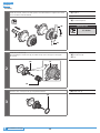
•
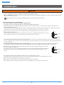
Make sure that even if the axle release lever is tightened as much as possible by hand, the axle release lever does not
interfere with the disc brake rotor.
If the axle release lever is on the same side as the disc brake rotor, there is a possibility they may interfere. If the lever
interferes with the disc brake rotor, stop using the wheel and consult a dealer or an agency.
Axle release
lever
Disc brake
rotor
•
HB-M7010/M7010-B/M6010/M6010-B/M618/M618-B/MT400/MT400-B can only be used in combination with the special front fork and through axle.
If used in combination with any other front fork or through axle, it may cause the wheel to become detached from the bicycle while riding and result
in serious bodily injury.
•
FH-M7010/M7010-B/M6010/M6010-B/M618/M618-B/MT400/MT400-B can only be used in combination with the special frame and through axle.
If used with any other type of frame, the wheel may come off while the bicycle is being ridden, and serious injury may occur as a result.
•
Make sure that even if the quick release lever is tightened as much as possible by hand, the quick release lever does
not interfere with the disc brake rotor.
If the quick release lever is on the same side as the disc brake rotor, there is the danger that it may interfere with the
disc brake rotor. If the lever interferes with the disc brake rotor, stop using the wheel and consult a dealer or an
agency.
Quick release
lever
Disc brake
rotor
•
If it is difficult to install the wheel, install the quick release lever on the disc brake rotor side.
If doing this, make sure that the quick release lever does not interfere with the disc brake rotor and that burns do not occur.
•
Make sure to properly install the quick release hub onto the bicycle.
Otherwise the wheel may detach from the bicycle while riding, resulting in serious injury.
•
After reading the owner's manual for the quick release lever thoroughly, keep it in a safe place for later reference.

5
TO ENSURE SAFETY
For Installation to the Bicycle, and Maintenance:
•
When installing the front wheel to the front suspension fork, always be sure to follow the directions given in the manual for the front suspension
fork.
The securing method and tightening torque for the front wheel both vary depending on the type of front suspension fork being used. If the
instructions are not followed, the front wheel may fall out of the front fork and serious injury may occur. When the front wheel is tightened onto the
front suspension fork in accordance with the tightening torque in the manual, the front wheel's rotation may become stiff; however, the instructions
must always be followed.
•
Use a SHIMANO hub axle.
If a different hub axle is used to secure the hub, it may not have sufficient strength to secure the freehub, or the axle may break because of
insufficient strength, and this may cause the wheel to fall off, and serious injury may occur.
•
Be sure to also carefully read the owner's manual for the disc brakes.
Quick release type
•
Use a front fork which is equipped with a wheel retention mechanism.
CAUTION
For Installation to the Bicycle, and Maintenance:
•
When using the SHIMANO original tool (TL-FC36) to remove and install the disc brake rotor lock ring, wear gloves and be careful not to touch the
outer edges of the disc brake rotor with your hands.
Failure to do so may result in cuts to your hands.
NOTICE
Be sure to also inform users of the following:
•
This product is not warranted against damage resulting from improper use, such as jumping while riding or if the bicycle falls over, except if such
malfunctions are caused by manufacturing methods.
•
Products are not guaranteed against natural wear and deterioration from normal use and aging.
•
For maximum performance we highly recommend SHIMANO lubricants and maintenance products.
For Installation to the Bicycle, and Maintenance:
•
If the wheel becomes stiff and difficult to turn, lubricate it with grease.
•
Do not lubricate the internal parts of the hub. Otherwise, grease will flow out.
•
When replacing the E-THRU Axle, make sure that the replacement E-THRU Axle is of the same model as the current E-THRU Axle attached to the
frame.
A different model may not be mounted properly onto the frame due to differences in axle length, screw size, housing diameter, etc.
•
Use the TL-HB16 when attaching the front hub to the wheel truing tool.
•
SM-AX56/SM-AX56-B/SM-AX58/SM-AX58-B cannot be used because the model is not designed for downhill bicycle riding or freeriding.
The actual product may differ from the illustration because this manual is intended mainly to explain the procedures for using
the product.

LIST OF TOOLS TO BE USED

7
LIST OF TOOLS TO BE USED
LIST OF TOOLS TO BE USED
The following tools are needed for installation, adjustment, and maintenance purposes.
Tool Tool Tool
10 mm hexagon wrench 17 mm hub spanner TL-FC36
TL-FH15 22 mm hub spanner TL-LR15
13 mm hub spanner Adjustable wrench

INSTALLATION

9
INSTALLATION
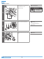
Spoke lacing
INSTALLATION
Spoke lacing
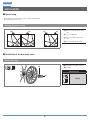
Check that the spokes have been laced as shown in the illustration.
A radial lacing cannot be used.
Rotating direction of wheel
(w) (x) (y) (z)
(w)
For front: Left (disc brake rotor)
side
(x)
For front: Right side
(y)
For rear: Left (disc brake rotor)
side
(z)
For rear: Right (sprocket) side
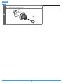
Installation of the disc brake rotor
Quick release type
(A)
(B)
(A)
Disc brake rotor fixing lock ring
(B)
TL-LR15
Tightening torque
40 N·m

10
INSTALLATION
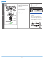
Installation of the disc brake rotor
E-THRU Axle
(A)
(B)
(A)
Disc brake rotor fixing lock ring
(B)
TL-FC36
Tightening torque
40 N·m

MAINTENANCE

12
MAINTENANCE
Front hub
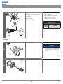
MAINTENANCE
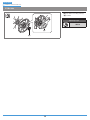
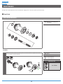
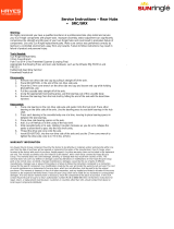
The hub can be disassembled as shown in the illustration. Apply grease to the various parts at periodic intervals.
Front hub
HB-M7000/M6000/M4050
(z)
(z)
(z)
Apply grease: Premium grease
(Y-04110000)
Assembly
Install the hub axle, and then use hub spanners as in the illustration to tighten the lock nut
so as to double-lock the mechanism.
(z)
Tighten
(A)
17 mm hub spanner
(B)
13 mm hub spanner
Tightening torque
10 - 15 N·m
(z)
(A)
(B)

13
MAINTENANCE
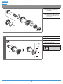
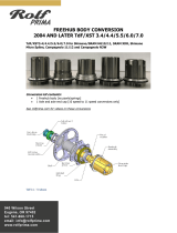
Front hub
HB-M7010/M7010-B/M6010/M6010-B/M618/M618-B/HB-MT400/HB-MT400-B
(z)
(z)
(C)
(z)
Apply grease: Premium grease
(Y-04110000)
(C)
Adjusting Spacer (Depending on
the hub, an adjusting spacer may
not be used.)
Assembly
Install the hub axle, and then use hub spanners as in the illustration to tighten the lock nut
so as to double-lock the mechanism.
(z)
Tighten
(A)
Hub axle
(B)
22 mm hub spanner
Tightening torque
21 - 26 N·m
(z)
(B)
(A)

14
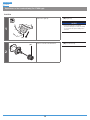
MAINTENANCE
Freehub
Freehub
NOTICE
•
When removing and installing the seal, do so very carefully so that the seal does not become bent. When reinstalling the seal, make sure that it is facing the right
way, and insert it as far as it will go.
•
Do not disassemble the dust covers which are crimped onto the axle, the right nut and the cone.
•
Do not attempt to disassemble the freewheel body, because it may result in a malfunction.
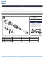
FH-M7010/M7010-B/M6010/M6010-B/M618/M618-B/FH-MT400/FH-MT400-B
(A)
(z)
[1]
[2]
(z)
(z)
Apply grease: Premium grease
(Y-04110000)
(A)
Seal (Lip is on the outside)
NOTICE
The correct position for the dust cover is
where it is hidden in the freewheel body, as
shown in illustration [1].
If the dust cover is in the position shown in
illustration [2], repeat the assembly process
from the beginning.
[1] [2]
Freewheel body
Dust cover
Part name Thread type Tool Tightening torque
[1] Left hand lock nut (M15) Clockwise thread 17 mm hub spanner 15 - 20 N·m
[2] Left hand cone (M15) Clockwise thread 17 mm hub spanner -
Assembly
Perform the assembly in the reverse order from the freewheel body replacement procedure.

15
MAINTENANCE
Freehub
FH-MT500/FH-MT500-B/FH-MT510/FH-MT510-B
(A)
(B)
(C)
(y)
(y)
(z)
[1]
[2]
(z)
(y)
Apply grease: Special freehub
grease (Y-3B980000)
(z)
Apply grease: Premium grease
(Y-04110000)
(A)
Seal (Lip is on the outside)
(B)
Freewheel body
(C)
Outer seal cap (convex section on
inner diameter is outward)
Part name Thread type Tool Tightening torque
[1] Left hand lock nut (M15) Clockwise thread 17 mm hub spanner 15 - 20 N·m
[2] Left hand cone (M15) Clockwise thread 17 mm hub spanner -
NOTICE
•
Perform the assembly according to the assembly procedures when the freewheel body has been removed.
•
Special grease is used for the freewheel body. Do not mix it with other types of grease, as this may cause problems with the operation of the freewheel clutch
mechanism.
•
Do not attempt to disassemble the freewheel body, because it may result in a malfunction.
•
Apply special freehub grease to the areas indicated in the figure.

16
To be continued on next page
MAINTENANCE
Freehub
Assembly
1
Install the hub axle, and then use hub spanners as in the illustration to tighten the lock nut
so as to double-lock the mechanism.
(z)
Tighten
(A)
Hub axle
(B)
17 mm hub spanner
Tightening torque
15 - 20 N·m
(A)
(B)
(B)
(z)
2
Install the freewheel body.
After installing the freewheel body, check that the lip of the seal ring is not facing the
wrong way.
(A)
Seal ring
(B)
Freewheel body
(C)
Lip
(A)
(B)
(C)
3
Insert the outer seal cap into the grooved part and install it.
(A)
Outer seal cap
(A)

17
MAINTENANCE
Freehub
4
Install the right cap.
Be sure to push it until it connects with a click.
(A)
Right cap
(A)

18
MAINTENANCE
Freehub
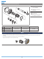
Replacement of the freewheel body (For QR type)
FH-M7000/M6000/M4050
(A)
(B) (C)
(D)
(y)
(z)
(E)
After removing the hub axle, remove the
freewheel body fixing bolt (inside the
freewheel body), and then replace the
freewheel body.
(y)
Disassembly
(z)
Assembly
(A)
Seal (Lip is on the outside)
(B)
Freewheel body
(C)
Freewheel body fixing bolt
(D)
Freewheel body washer
(E)
10 mm hexagon wrench
(TL-WR37)
Tightening torque
35 - 50 N·m
FH-MT500
1
(A)
Remove the right cap.
(A)
Right cap
NOTICE
•
Position the right cap so it is facing
downward and support it with your thumb,
etc. to prevent the cap from falling as it is
removed.
2
(A)
Remove as shown in the illustration.
(A)
Freewheel body

19
MAINTENANCE
Freehub
Replacement of the freewheel body (For E-THRU type)
FH-MT510
1
(A)
Remove the right cap.
(A)
Right cap
NOTICE
•
Position the right cap so it is facing
downward and support it with your thumb,
etc. to prevent the cap from falling as it is
removed.
2
(A)
Remove as shown in the illustration.
(A)
Freewheel body

20
To be continued on next page
MAINTENANCE
Freehub
Other than FH-MT510
1
(z)
(A)
Use the spanner to loosen the lock nut
on the double-lock section.
(z)
Disassembly
(A)
17 mm hub spanner
Tightening torque
15 - 20 N·m
2
(A)
(B) (C)
Remove as shown in the illustration.
(A)
Lock nut
(B)
Cone with dust cover
(Cannot be disassembled)
(C)
Seal ring
3
(A)
Pull out the hub axle from the freewheel
body.
(A)
Hub axle
Page is loading ...
Page is loading ...
-
 1
1
-
 2
2
-
 3
3
-
 4
4
-
 5
5
-
 6
6
-
 7
7
-
 8
8
-
 9
9
-
 10
10
-
 11
11
-
 12
12
-
 13
13
-
 14
14
-
 15
15
-
 16
16
-
 17
17
-
 18
18
-
 19
19
-
 20
20
-
 21
21
-
 22
22


Ask a question and I''ll find the answer in the document
Finding information in a document is now easier with AI
Related papers
Other documents
-
Saris Direct Drive Cassette User manual
-
Yamaha MT400 User manual
-
Micromax Canvas Blaze Owner's manual
-
 SUNringlé SRC SRX hub Owner's manual
-
Samsung M6000 User manual
-
Bontrager 231793 User manual
-
Toshiba MT400 User manual
-
Axis Communications M7010 User manual
-
 Rolf PRIMA Freehub Body Conversion Operating instructions
-
scope R3D Maintenance Manual

