Page is loading ...

© Danfoss | 2017.11
VI.KS.F4.02
District Heating Substations
suitble for indirect heating / cooling, dhw production
and other water based heating systems
Operating Guide
Please always keep the instructions close to the device!
Please read the instructions carefully
before starting any work.
In case of wrong installation
Danfoss could change warranty terms!
Attention!
Before starting up the station, please check
it for proper function and free of defects!
VIKSF402_new layout.indd 1 2017-11-23 09:44:28

2 | © Danfoss| 2017.11
VI.KS.F4.02
District Heating Substations
1.0 General notes .......................................................................................................................................................................................................................................3
1.1 Information about Operating Instructions ...........................................................................................................................................................................3
1.2 Applicable Documents ................................................................................................................................................................................................................3
1.3 Explanation of symbols ............................................................................................................................................................................................................... 3
1.4 Liability and Warranty ...................................................................................................................................................................................................................3
1.5 Copyright Protection ....................................................................................................................................................................................................................4
1.6 Spare parts .......................................................................................................................................................................................................................................4
1.7 Substation disassembly ...............................................................................................................................................................................................................4
1.8 Disposal ............................................................................................................................................................................................................................................4
2.0 Safety ................................................................................................................................................................................................................................................5
2.1 General information ..................................................................................................................................................................................................................... 5
2.2 Responsibility of substation operator .................................................................................................................................................................................. 5
2.3 Intended use ...................................................................................................................................................................................................................................5
2.4 Possible misuse ..............................................................................................................................................................................................................................5
2.5 Safety work ......................................................................................................................................................................................................................................5
2.6 Personal protective equipment ...............................................................................................................................................................................................6
2.7 Risks associated with the substation ..................................................................................................................................................................................... 6
2.8 Emergency stop switch ..............................................................................................................................................................................................................7
2.9 Operators .........................................................................................................................................................................................................................................7
2.10 Steps to follow in the event of danger or accidents ........................................................................................................................................................7
2.11 Residual hazards / risk analysis ................................................................................................................................................................................................8
3.0 Technical data ......................................................................................................................................................................................................................................9
3.1 Technical information ..................................................................................................................................................................................................................9
3.1.1 CE label ................................................................................................................................................................................................................................... 9
3.1.2 Dimensions and packaging ............................................................................................................................................................................................9
3.2 Symbols used in circuit diagrams ......................................................................................................................................................................................... 10
4.0 Function and conguration ......................................................................................................................................................................................................... 10
4.1 Function ......................................................................................................................................................................................................................................... 10
4.2 DSE FLEX conguration possibilities ................................................................................................................................................................................... 11
5.0 Transport, packaging and storage ............................................................................................................................................................................................. 12
5.1 Transport of pallets by forklift .............................................................................................................................................................................................. 12
5.2 Transport inspection ................................................................................................................................................................................................................. 12
5.3 Packaging ..................................................................................................................................................................................................................................... 13
5.4 Storage ......................................................................................................................................................................................................................................... 13
6.0 Installation .......................................................................................................................................................................................................................................... 13
6.1 Installation preparation ......................................................................................................................................................................................................... 14
6.1.1 Primary connection ........................................................................................................................................................................................................ 14
6.1.2 Secondary connection ................................................................................................................................................................................................... 14
6.1.3 Electrical connection ...................................................................................................................................................................................................... 14
6.2 Draining station ........................................................................................................................................................................................................................ 17
7.0 Commissioning ................................................................................................................................................................................................................................. 18
7.1 Requirements for commissioning ...................................................................................................................................................................................... 18
7.2 Secondary side commissioning .......................................................................................................................................................................................... 18
7.3 Primary-side commissioning ............................................................................................................................................................................................... 18
7.4 Requirements for commissioning ...................................................................................................................................................................................... 19
7.5 Fault and Shutdown ................................................................................................................................................................................................................ 19
7.6 Commissioning after a failure or malfunctioning ........................................................................................................................................................ 19
8.0 Operation .......................................................................................................................................................................................................................................... 19
8.1 Switching on .............................................................................................................................................................................................................................. 19
8.2 Switching o .............................................................................................................................................................................................................................. 19
8.3 Restarting after substation shutdown .............................................................................................................................................................................. 19
8.4 Service / clean - strainer .......................................................................................................................................................................................................... 20
8.5 Service / disassembly and replacement - heat exchanger ......................................................................................................................................... 21
8.6 Service / Check - Safety valve and expansion vessel .................................................................................................................................................... 21
9.0 Maintenance .................................................................................................................................................................................................................................... 22
9.1 Safety warning .......................................................................................................................................................................................................................... 22
9.2 Maintenance plan (recommendations) ............................................................................................................................................................................ 22
9.3 Heat exchanger maintenance ............................................................................................................................................................................................. 23
9.4 Maintenance validation ......................................................................................................................................................................................................... 23
10.0 Troubleshooting ..................................................................................................................................................................................................................... 24
10.1 Safety .......................................................................................................................................................................................................................................... 27
11.0 Spare parts ................................................................................................................................................................................................................................ 27
12.0 Index .................................................................................................................................................................................................................................. 28
Table of contents
VIKSF402_new layout.indd 2 2017-11-23 09:44:28

© Danfoss | 2017.11 | 3
VI.KS.F4.02
District Heating Substations
1.0 General notes
1.1 Information about Operating Instructions
This manual describes the installation, operation and maintenance
of the substation. Compliance with all safety and operating instruc-
tions is a prerequisite for the safe operation and proper use of the
substation. In addition, regulations applicable to the eld of appli-
cation of the substation, local accident prevention regulations and
general safety regulations must be followed. The operating manual
is part of the product and must be available at all times within the
immediate vicinity of the operating area of the substation for the
installation, operation, maintenance and cleaning responsible of
the substation.
1.2 Applicable Documents
Individual system components - unless otherwise indicated - are
components purchased from other manufacturers. All components
used in the substation have been subjected to their manufacturers’
risk assessments. Declarations of conformity with current European
and national legislation have been made by the manufacturers of
the components. Declarations of conformity, and operation, main-
tenance and repair instructions for the individual components are
integral parts of the substation documentation.
1.3 Explanation of symbols
Important security and device-related information in these oper-
ating instructions is marked by warning notices. The instructions
must be followed to prevent accidents, personal injury or property
damage.
1.4 Liability and Warranty
All information and instructions in this manual have been compiled
in accordance with applicable regulations and the current status of
engineering developments as well as our many years of knowledge
and experience. The actual scope of delivery may dier from the ex-
planations and graphic representations of special versions described
here, as a result of additional accessories / order options or latest
technical changes. For questions, please contact Danfoss directly.
We reserve the right to make technical changes to the product in
the course of improvement of its functional properties and further
development. Items such as tools and equipment that may wear out
during use of the device, as well as auxiliary materials and supplies
such as oils, greases and detergents, are not covered by warranty.
The graphic illustrations in this manual are provided to better repre-
sent the issues described, and are not necessarily to scale and may
dier slightly from the actual design of the substation. In addition
to these operating instructions, operating manuals for all installed
components on substation must be followed. The information con-
tained therein - particularly with regard to safety - must be followed!
The instructions contained in the manufacturer’s documents for se-
curity, set-up, installation, operation, maintenance, and dismantling
and disposal of the components must be followed strictly.
In addition, the commitments agreed in the contract, such as the
general terms and conditions and the manufacturer’s terms of deliv-
ery, and statutory regulations at the time the contract is concluded
shall apply.
NOTE
This symbol highlights tips and information that must be followed
for the ecient and trouble-free operation of the substation.
WARNING
This symbol indicates a danger that may result in damage to health,
injury, permanent physical injury or death. Please follow the notes
for working safely very carefully and take extreme care in these
situations!
ATTENTION
This symbol indicates a risk that may result in damage to, or
malfunction / failure of equipment if ignored.
WARNING
Electrical hazard! This symbol indicates danger from electricity.
Failure to follow safety procedures can result in severe injury or
death. This work may only be performed by a trained electrician.
NOTE
These operating instructions should be read carefully before starting
work on or with the substation, and in particular before commission-
ing! The manufacturer will not accept claimsfor damage or faults
arising from non-compliance with these operating instructions.
VIKSF402_new layout.indd 3 2017-11-23 09:44:28

4 | © Danfoss | 2017.11
VI.KS.F4.02
District Heating Substations
1.5 Copyright Protection
Operating instructions must be kept condential. These are intend-
ed exclusively for the persons employed on and with the substation.
Transfer of the operating instructions to third parties without writ-
ten approval of the manufacturer is prohibited. If such approval is
required, please contact Danfoss directly.
This document and any others delivered with the substation are pro-
tected by copyright. Copies (whether whole or in part) are allowed
only with the permission of the manufacturer. Violators will be liable
to prosecution. All other rights reserved.
1.6 Spare parts
Use only original spare parts from the manufacturer.
The use of non-approved spare parts will invalidate any guarantees,
or service, compensation and liability claims against the manufacturer
or its agents, distributors and representatives.
1.7 Substation disassembly
Clean and sort the substation parts and components in compliance
with applicable health and safety and environmental regulations.
Before starting disassembly:
• Switch the unit OFF and secure against being
switched ON again.
• Ensure that the entire energy supply is physically separate
from the substation and that stored residual power is properly
discharged.
• Remove supplies and materials as well as any remaining
processing materials in an environmentally friendly manner.
1.8 Disposal
If no withdrawal or waste management agreement has been con-
cluded, disassemble the dismantled components for recycling:
• Metal to scrap material
• Plastics to plastics recycling
• To dispose other components, sort by material properties
• Remove any residual media and dispose of properly media with
additives (e.g. glycol) must comply with relevant legislation
Remove operating materials such as lubricants, oils, fats, cleaning
agents and inhibitors from the substation in an environmentally
friendly manner . In this case, use a suitable, approved container for
lubricants. Mark the container with information about the content
and level, and date clearly. Secure nal disposal of the materials so
that improper use is excluded.
NOTE
Contents of this instruction – texts, drawings, images or other illus-
trations are copyrighted and subject to other intellectual property
rights. Any improper reuse is forbidden.
ATTENTION
Using the wrong or faulty spare parts can lead to damage,
malfunction or total failure of the substation.
WARNING
Risk of injury! Stored residual power, components with sharp edges,
edges and corners on and inside the substation or necessary tools
can cause personal injury. Any substation removal work must there-
fore be carried out only by a specialist.
WARNING
Do not drink!
Water in the installation which has not been used for a long period
of time may not meet the quality standard for drinking water in
certain conditions. Prevent such use and drain or dispose of water
used to run the substation.
WARNING
Electrical and electronic components, lubricants and other excipients
must be handled by hazardous waste treatment plants and may only
be disposed by approved specialist companies!
VIKSF402_new layout.indd 4 2017-11-23 09:44:28

© Danfoss | 2017.11 | 5
VI.KS.F4.02
District Heating Substations
2.0 Safety
This section gives an overview of all the important security aspects
of optimal protection of personnel as well as of safe and trouble-
free operation of the substation. In addition, these chapters include
specic safety symbols in order to avert immediate safety hazards.
2.1 General information
Substation is built at the time of its development and manufactur-
ing according to existing, accepted engineering standards and is safe
to operate. The substation can be dangerous if used by improperly
trained personnel or used improperly or by unauthorised persons. Any
person authorised to work on or with the substation must read and
understand the operating instructions before starting work. We recom-
mend advising the operator to obtain conrmation from sta proven
understanding of the instruction manual. Modications of any kind
as well as additions or modications to the substation are forbidden.
All substation security, warning and operating instructions must be
maintained in good legible condition. Damaged labels or stickers
must be replaced immediately. Specied values or ranges must be
strictly adhered to.
2.2 Responsibility of substation operator
• Operating instructions must always be stored within the
immediate vicinity of the substation and must be accessible
at all times for installation, operation and maintenance and to
cleaning sta.
• Operate the substation only if it is in a proper
technical and safe operating condition.
• Check that safety devices are always kept freely
accessible test them regularly.
Information about industrial safety is based on the European Union
regulations valid at the time of manufacture of the substation. The
operator is obliged throughout the entire lifetime of the substa-
tion to conform to those safety actions designated in the current
rules and regulations and to comply with those in new regulations.
Outside of the European Union, the safety laws, local rules and
regulations applicable to the location where the substation oper-
ates must be followed.
2.3 Intended use
Operational safety is guaranteed only where the substation is used
properly and in accordance with the instructions / details in this
manual. A district heating substation is used to provide heat energy
from the district heating utility grid by transferring heat to customer
installation systems. Intended use also includes compliance with
instructions for installation, operation, maintenance and cleaning.
2.4 Possible misuse
In addition to the safety instructions in this manual, and for sub-
station safety in general, accident prevention and environmental
protection regulations must be observed and followed. The opera-
tor and authorised personnel are responsible for the trouble-free
operation of the substation, as well as for the clear denition of re-
sponsibilities for installation, operation, maintenance and cleaning
of the substation. There must be no deviation from the information
in the operating instructions!
The operator shall also ensure that:
• Any further risks are identied in an assessment of risks arising
from the special working conditions at the operations site.
• That any additional work and safety instructions resulting from
the risk assessment of activities performed on the substation
are described in a standard operating procedure (SOP).
Always follow local regulations as well as any existing ordinances
on industrial safety and health (e.g. in Germany: BetrSichV, BGBL
I 2002, 3777).
Any additional and / or other use of the substation is forbidden
and considered as improper use! Any claims against the manufac-
turer and / or its representative for any loss or damage as a result
of improper use of the substation are excluded. The operator and
/ or owner shall be solely liable for any damage arising when the
substation is used for any purpose other than.
Therefore:
• Use the district heating transfer station only for its intended
purpose and in accordance with the information provided
in this document, particularly the limitations given in the
technical data.
• Avoid any further or other use of the district heating transfer
station.
• It is forbidden to change, upgrade or modify the design or
individual components for the purpose of changing the
station’s range of usability or application.
NOTE
For modication and extension activities, always consult with the
substation manufacturer.
WARNING. Hazard from improper use!
Any use of the substation apart from its intended use may lead
to dangerous situations.
2.5 Safety work
Hazards to persons and / or the system can be prevented by fol-
lowing the safety at work instructions.
VIKSF402_new layout.indd 5 2017-11-23 09:44:28

6 | © Danfoss | 2017.11
VI.KS.F4.02
District Heating Substations
2.6 Personal protective equipment
While working on and with the substation the following must be
worn at all times:
2.7 Risks associated with the substation
The substation has been subjected to a risk analysis based on the
design and construction of the substation and in correspondence
with the current state of technology. Nevertheless, risks remain! The
substation can generate a hot stream of uid or steam when e.g.
adrain or air vent is opened.
The substation operates with high electrical voltages of up to 400 V
and currents of up to 25 A.
• Switch OFF the main switch and secure against reconnection
before performing any maintenance, cleaning or repair.
• Turn o the power switch when performing any work with the
electrical system
• Do not remove any safety devices or put out of operation
The substation is supported by pneumatic components.
Therefore:
• Depressurise before starting any work on the substation.
• Do not remove or alter any safety devices or put out of service.
• Do not change the default settings from the values or beyond
the tolerance ranges specied in the operating manual
The substation has sharp edges and corners.
Components inside of the station can contain automatically moving
parts (pumps, actuators, etc.). The devices can be very heavy.
Protective clothing
is close-tting work clothing with low tensile strength and tight
sleeves and without protruding parts. Its main purpose is to guard
against snagging on moving machine parts. Do not wear rings,
chains or other jewelry.
Protective gloves
to protect the hands from friction, abrasion, puncture or deeper
injury as well as from contact with hot surfaces.
Protective goggles
to protect the eyes from ying parts and liquid splashes.
Safety shoes
to protect from heavy falling parts and losing traction on slippery
surfaces.
Helmet
to protect against falling or ying parts and materials.
WARNING! Risk of injury!
Risk from liquids splashing under high pressure. Wear personal pro-
tective equipment for all operations carried out on the substation!
WARNING! Electrical shock hazard!
Electrical energy can cause serious injury. Damaged insulation or
components can lead to serious injury or death.
WARNING! Risk of injury!
Risk from liquids splashing under high pressure. Wear personal pro-
tective equipment for all operations carried out on the substation!
WARNING! Risk of injury!
Sharp-edged parts and sharp edges may cause abrasion to the
skin. Wear protective gloves when working on the substation.
WARNING! Risk of burns!
Hot surfaces can cause serious burns. For all operations carried
out on the substation always wear protective gloves!
WARNING! Danger of crushing!
During transport or lifting of the substation, bruising can occur
due to heavy weight. The substation may include electrical com-
ponents (engines, transmissions) which may also cause bruising
if contacted while in operation. For all operations carried out on
the substation, always switch the main supply OFF and wear pro-
tective clothing.
VIKSF402_new layout.indd 6 2017-11-23 09:44:29

© Danfoss | 2017.11 | 7
VI.KS.F4.02
District Heating Substations
2.8 Emergency stop switch
The operator shall ensure that the emergency stop switch is installed
in accordance with applicable accident prevention regulations. The
operator must inform operations sta about the location and opera-
tion of the emergency stop switch.
2.9 Operators
The substation may be operated and maintained only by authorised,
trained and instructed personnel. These personnel must receive spe
-
cial training on potential risks. An “instructed person” is a person who
has been informed of the tasks assigned to him/her and the potential
hazards of improper usage and, if necessary, who has been trained
and instructed in protective equipment and actions.
A “professional” is a person who, because of his/her technical train-
ing, knowledge, and experience, as well as his/her knowledge of the
relevant provisions, can evaluate the work transferred to him/her and
recognise possible dangers.
If the sta do not have the knowledge required, then they must be
trained. Responsibilities for operation and maintenance must be
clearly dened and respected so that there is no unclear division of
responsibilities in terms of safety.
2.10 Steps to follow in the event of danger or accidents
In the event of an emergency or accident, the substation must be
switched OFF by immediately pressing the emergency stop switch.
This can be done by opening the safety door or protective window
equipped with safety switches that trigger the emergency stop func-
tion when opened.
Safety devices with an emergency stop function are only to be used
in appropriate situations.
The substation may only be operated and maintained by persons
who can be expected to reliably run their work. Any operation that
aects the safety of persons or the substation environment must be
avoided. Persons under the inuence of drugs, alcohol or medica-
tion that aects responsiveness must not perform any work with or
on the substation. When selecting personnel, the relevant country’s
youth employment protection regulations as well as any occupation-
specic regulations that may exist must be followed with respect to
minimum age.
The operator must ensure that no unauthorised persons are work-
ing on or with the substation. Unauthorised persons such as visitors,
guest etc., must not come into contact with the substation. You must
maintain a reasonable safety distance. The user is obliged to immedi-
ately report any issues which occur in the substation and may aect
the safety of the operator.
Safety equipment must not be used for normal shutdown of the
substation. Always be prepared for accidents or re! Keep rst-aid
equipment (rst-aid kit, eye wash, etc.) and a re extinguisher within
the substation area.
Personnel must be trained in the handling and location of safety
devices, accident procedures, rst aid and rescue equipment. This
results in the prevention of dangerous situations and ensures the
best possible assistance in the event of an accident.
VIKSF402_new layout.indd 7 2017-11-23 09:44:29

8 | © Danfoss | 2017.11
VI.KS.F4.02
District Heating Substations
2.11 Residual hazards / risk analysis
During operation, residual risk can be limited to the following al-
phabetic values according to the Suva (Assessment and Reduction
of risks from machines) risk assessment: B5/C4/D3/E2. The residual
potential for danger arises from failure to comply with the above
instructions. The assembly has been manufactured according to the
explicit specications of the customer, who is responsible for com-
pliance with the parameters specied and the selection of qualied
operating personnel.
The substation is equipped with the following warning on which the
key residual risks are point out again:
Risk place Risk type Protective aim Measure
Shut-o valves and ttings
in the station
Crushing during
manual operation
Manual operation of the
shut-o valves and ttings
must be safe
Due to construction, provide
enough space for ergonomic
operation
Piping and components
in the station
Burning when touched Safe contact at the station
Thermal insulation of pipes
and components, signs at the
station, warnings in the
operating instructions
Entire station Electric shock Safe contact with the station Fullment of contact protection
Entire station
Splashing of liquids and/or
steam at high pressure
Controlled reduction of excess
pressure in case of fault
Protection according to local
standards or legal regulations
(e.g. DIN 4747 T1
or DIN EN 12828)
Entire station
Overheating the station
or transmitting heat to
a connected system at
a temperature above
what is permissible
Turning o the heat supply
in case of failure
Protection according to local
standards or legal regulations
(e.g. DIN 4747 T1
or DIN EN 12828)
Operation of this substation is permitted only by trained personnel after detailed study
of the enclosed documentation. The system must be lled and completely vented
before commissioning. Do not exceed the maximum allowable working pressure or
maximum allowable operating temperature specied on the label. Any use other than
the proper use is prohibited.
Risk of burns from touching or from the release of hot media (water/steam).
Avoid touching the substation or wear suitable protective clothing!
Risk of crushing during assembly and operation.
Risk of electric shock. Check that the substation is disconnected before
working with the electrical system.
All ange and threaded connections, ttings, electrical clamps and screw connections
must be checked and tightened as necessary before lling or commissioning.
Run pumps only when lled with water (no dry run!)
Before starting up the substation properly install the following (unless fully
assembled in factory):
- Safety valve, drain and air vent according to EN12828 or EN806, unless local
standards are available.
- Strainer in the primary ow and secondary return pipeline
- Equipotential bonding according to IEC60364-4-41:2005 (grounding / protective
conductor / potential equalisation), unless local standards are available
(e.g. DIN VDE 0100:540:2012-06)
VIKSF402_new layout.indd 8 2017-11-23 09:44:29

© Danfoss | 2017.11 | 9
VI.KS.F4.02
District Heating Substations
C
A2
B
3.0 Technical data
3.1 Technical information
Main substation information can be found on the CE label as
well as in documents contained in the appendices (circuit and
electrical diagram, data sheet).
3.1.1 CE label
The CE label is attached to the substation.
It contains the following information:
• Manufacturer
• Serial no.
• Production date (year / calendar week)
• Substation code / Type (Name)
• Applications
• Category according to PED directive
• Power supply voltage
• PN class
• Minimum and maximum operating temperatures
• Maximum allowed pressure by maximum operating temperature
• Capacity
• Temperature programme
• Heat exchanger type
• Volumetric ow
• Pressure drop inside heat exchanger
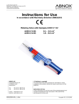
3.1.2 Dimensions and packaging
The range of tailored product dimensions and weights can be found
in the manual.
The DSE is manufactured upon customer request; its dimensions
and weight may vary depending on accessories selected. Details
of dimensions and weight are available before delivery to ensure
trouble-free transport and installation of the substation.
Figure 1: Danfoss Substations external dimensions
DSE MAXI
VIKSF402_new layout.indd 9 2017-11-23 09:44:33

10 | © Danfoss | 2017.11
VI.KS.F4.02
District Heating Substations
3.2 Symbols used in circuit diagrams
Pressure transmitter
4.0 Function and conguration
4.1 Function
The substation is an indirect compact substation, where heat transfer
from the district heating or cooling network to a secondary installa-
tion is realised via heat exchangers. This solution ensures hydraulic
system separation.
The basic idea of heat transfer in a compact substation is connect-
ing the primary side of the piping to the district heating company’s
network, which supplies hot water within the appropriate parameters
(such as for pressure and temperature), and the secondary piping to
the customer’s installation on the other side. Network parameters
may vary depending on the season and may be higher during the
winter season and lower during the warmer months. Primary me-
dium ow normally through shut-o valve and strainer In addition
for pressure and temperature measurements, usually pressure gauge
and thermometer are assembled, if it is needed according to the
specication of District Heating Utility on primary ow and/or return
pipe. Cooled heating water ows back through the primary return
pipline to the district heating network.
In a District Cooling system the chilled water is (lower temperature
for example 7 deg. C) is entering the heat exchanger through the
primary ow pipe and warmed water (for example 12 deg. C) it ows
back through the primary return pipe to the District Cooling network.
In the secondary circuit circulation pump transfers heated water to
the heating surfaces of other installations (e.g. ventilation equip-
ment, drinking water or heating installations, etc.). If a controller
with weather compensation is installed at the substation, it has the
following essential functions:
• Measures ow temperature on the secondary side and
outdoor temperature
• Changes the stroke of the control valve on the primary side so
that it conforms to the required secondary temperature
• Limits the return temperature on the primary side to a value
preset in the controller
• Switches the secondary side circulating pump(s) on and o as
necessary and ensures frost protection
If required, special functions are available according to needs and de-
signs. Refer to the instruction manual of the controller manufacturer.
All systems are oered upon request and manufactured in keeping
with the customer’s special operating conditions.
Due to the many dierent product variations, the circuit diagram
may dier from that presented below.
VIKSF402_new layout.indd 10 2017-11-23 09:44:34

© Danfoss | 2017.11 | 11
VI.KS.F4.02
District Heating Substations
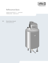
Figure 3: DSE FLEX conguration
Szafka sterownicza
PS
HE
DHW
TE
2B
QQ
PI
PI
PI PI
PI
PI
PIPIPI
PI
PI
PIPI
PI PI
PI
813 150
151423153151 160 161
171
34
395 182
174
167181 812
153
815 812
812 812 151
153
419
419
445
420
465395
411
443151
474 153470 419419419430 468 430
171
423 419
85
E
15185 81
A
812
E
80
S
34
812
80
151 812 2670
151
A
812
151
812
151
750
753
95
812814
PS
PI
PI
PI PI
PI
820 340
361
395 377
377
357376 819
343
822 819
819 819 34175 8480
75 819821
7542315375 160 161
QQ
S
E
E
80
QQ
S
E
E
26 Control valve HE
34 Drain valve
35 Thermometer
70 Mud trap
75 Ball valve
80 Heat meter + sensors
81 DP controller + pressure point
84 Drain valve
85 Thermometer
95 Control valve DHW
150, 151 Ball valve
153 Strainer
160 Diaphragm
4.2 Danfoss Substation conguration possibilities
The substation can be used for various applications such as cool-
ing / heating, domestic hot water and / or other water based heat-
ing system. Due to its exibility, we have inserted in this document
only an example diagram, for the actual aplication please refer to
the manual. This is based on customer requests and the needed
application(s). The construction allows easy access to all components
for maintenance and servicing purposes. Heat transfer between the
district heating network and the building installation is achieved by
way of a heat exchanger, which ensures better heat transfer, higher
energy eciency and reduced pressure loss.
In addition to the standard controller functions, the ECL310 oers
easy remote access via an internet page with data logging possibili-
ties and energy optimization functions such as weather compen-
sation and auto-tuning (adaptive settings for domestic hot water
parameters). Refer to the manual for the actual controller and apl-
lication key.
By use of the Danfoss dimensioning program you can nd out if the
application you need ts the Danfoss substation.
161 Water meter
164 Balancing valve
167 Pump
171 Drain valve
174 Thermometer
175 Temperature sensor
181 Temperature sensor
182 Thermometer
340, 341 Ball valve
343 Strainer
357 Pump
361 Drain valve
364 Thermometer
365 Thermometer
376 Temperature sensor
377 Thermometer
395 Safety thermostat
398 Balancing valve
411 Ball valve
419 Pressure measurement
420 Safety valve
423 Check valve
430 Ball valve
443 Temperature sensor
445 Thermometer
465 Ball valve
468 Check valve
470 Pump
472 Balancing valve
474 Thermometer
488 Temperature sensor
750 Electronic controller
753 Outdoor sensor
811, 818 Pressure transmitter
812, 819 Manometer
813, 814 Safety valve
815, 822 Expansion valve
820, 821 Safety valve
Electrical box
VIKSF402_new layout.indd 11 2017-11-23 09:44:34

12 | © Danfoss | 2017.11
VI.KS.F4.02
District Heating Substations
5.0 Transport, packaging and storage
Follow general safety rules during transport:
• Adapt transportation to local conditions
• Use only approved lifting gear and lifting equipment
with adequate load capacity
• Only attach the substation to suitable anchor points and
not to protruding machine parts or any component’s
eylet or hole.
Ensure the secure t of the slings!
• Ropes and belts must be equipped with a safety hook. Do not
use damaged or frayed cables. Do not fasten ropes or straps
to sharp edges or corners and do not knot or twist. Always
consider the centre of gravity before handling
• Never lift, pan or lower loads over people
• Always transport the substation with the utmost care and caution
• During vessel transport especially bear in mind that: insulation
must not be damaged during transport or removed (especially
when transporting over longer distances)
• Ensure suitable means of transport so that no deformation
arises on connections or vessel
• Avoid direct contact with ferrous materials
or surface destruction of stainless steel vessels
5.1 Transport of pallets by forklift
Packages mounted on pallets can be transported by forklift under
the following conditions:
• The forklift must be designated according
to the weight of the handling units
• Operator must be authorised (licensed) to operate the forklift
Procedure:
1. Drive the forklift with the forks between
or under the tie bars of the pallet
2. Drive the forks far enough to protrude from
the opposite side of the pallet
3. Make sure that the centre of gravity
is between the forks and cannot tilt
4. Lift the package and start transport
Follow safety rules:
• Use only approved lifting gear and lifting equipment
with adequate load capacity
• Only attach the substation to suitable anchor points
and not to protruding machine parts or eyelet components.
Ensure the secure t of the slings!
• Ropes and belts must be equipped with a safety hook. Do not
use damaged or frayed cables. Do not fasten ropes or straps
to sharp edges and corners and do not knot or twist. Always
consider the centre of gravity before handling
• Never lift, pan or lower loads over people
• Always transport the substation with the utmost care and
caution
5.2 Transport inspection
Immediately after delivery check for completeness and any trans-
portation damage. In case of externally visible transport damage, do
not accept delivery or accept only conditionally. Note the extent of
damage on the transport documents / bill of delivery. Initiate acom-
plaint. Claim defects that are not visible immediately after detect-
ing, as claims for damages can be made only within the applicable
complaint periods.
WARNING! Danger to life!
When lifting, panning and lowering ,there is a risk of serious personal
injury and damage from falling parts. Never stand under suspended
loads!
WARNING! Danger to life!
When lifting, panning or lowering, there is a risk of serious personal
injury and damage from falling parts. Never stand under suspended
loads!
VIKSF402_new layout.indd 12 2017-11-23 09:44:34

© Danfoss | 2017.11 | 13
VI.KS.F4.02
District Heating Substations
5.3 Packaging
Substations are delivered with dierent types of packaging. Pack-
aging materials are primarily of wood, cardboard and plastics (foil,
foams). Strapping is in addition. Packaging material may also include
materials added to packages for moisture or frost protection (e.g.
silica gel bags, antifreeze, etc.). If no agreement has been made re-
garding the return of packaging material, the packaging material
remains with the customer.
Our transport packaging can be returned to Danfoss, at the manu-
facturing site. Please refer to the label.
5.4 Storage
After packages have been unloaded they must be stored until assem-
bly in accordance with the attached shipping marks. Machine parts
and accessories packaged in separate boxes must not be unpacked.
For storage, the following rules apply:
• Dry storage. Relative humidity: up to 60%
• Ensure that packages are not stored outdoors. In addition,
ensure that the storage room oor is dry during storage
• Keep out of direct sunlight. Optimal storage
temperature 15 to 25 C°
• Keep dust-free
• Avoid mechanical vibrations and damage
• For long-term storage of more than three months,
conservation activities should be taken In severe weather
conditions, conservation must be renewed as necessary
WARNING!
Unpaid delivered transport packaging will not be accepted
by Danfoss.
Packaging materials must be utilised in an environmentally friendly
way and in accordance with the relevant waste disposal regulations.
6.0 Installation
District heating transfer stations are usually completely pre-piped and
wired installations on a painted steel frame. All parts and components
are mounted or xed to the frame. External substation connections
are marked with easily understandable labels / stickers. Integrated
adjustable feet are used to compensate for uneven ground.
Secure durability of ground based on total weight of equipment
(including water content). Take care that each connection is stress-
free after assembly; the substation cannot be used as a xed point.
If substation parts or components must be removed due to
limited space for transport (corridors, elevators, small doors etc.),
ensure that they are reassembled exactly as they were in the
original place.
Pipe connections and tting connections can be prepared as:
• Welding ends
• Flanged connections acc. EN 1092
• Threaded connections acc. DIN 2999 (internal / external)
• Threaded connections acc. DIN 2993/ISO 228 (external)
WARNING! Risk of injury!
Improper installation and assembly can result in serious injury
and / or property damage. Installation and assembly work may be
performed only by qualied personnel in compliance with safety
regulations.
NOTE!
The use of pipe wrenches for nuts and bolts is not permitted. Only
use a suitable spanner!
NOTE!
The mechanical separation of substation components through
sawing, cutting, etc. of cabling and / or frame parts and piping is
not permitted.
VIKSF402_new layout.indd 13 2017-11-23 09:44:35

14 | © Danfoss | 2017.11
VI.KS.F4.02
District Heating Substations
6.1 Installation preparation
Substation installation should be carried out on a clean, at surface.
Stand-alone substations usually come with integrated adjustable
feet, which can compensate for uneven ground. If not pre-assembled,
these are supplied as loose components in an accessory pack and
can be screwed into the appropriate nuts in the bottom area of the
frame. Then adjust the station horizontally.
6.1.1 Primary connection
The primary connection must be made by qualied personnel in
consultation with local / district heating supply companies if the
installation is connected to such network. The primary supply and
return must be connected to the designated devices or the substa-
tion shut-o valves.
The commissioning of primary side connections to the district heat-
ing network is usually done by the relevant local / district heating
company.
• If substation is delivered (ordered) without a strainer on
primary inlet site, make sure it is separately mounted
before substation is connected to the network to protect all
components from potential damage. If this requirement is not
respected it may result in loss of warranty.
• After installation of substation to the network it is required to
splash pipes between main strainer and substation to remove
any potential particles.
6.1.2 Secondary connection
A specialised installation company connects the secondary installa-
tion to the substation’s designated shut-o valve.
After installation of substation to the network it is required to splash
pipes between main strainer and substation to remove any potential
particles.
6.1.3 Electrical connection
Only a qualied electrician approved by a responsible electric utilities
company may carry out the electrical installation of the substation
in compliance with all applicable rules and regulations. The substa-
tion is completely wired and tested at the factory by default for the
delivered components. If the station is ordered without controller or
other electrical components the wiring and test are not performed. If
an outdoor sensor for substation control is ordered, this is enclosed
in the loose component box and should be installed as far as this is
possible on the north side of the building.
The electrical diagrams for electrication are included in technical
documentation. Internal electrications are made in the factory.
The electric cables cannot be fastened with the hot pipes. They need
their own supporting structures.
The device should be properly installed and grounded by a qualied
technician. The appliance should be serviced only by qualied service
personnel. Repair interventions by unauthorized persons may cause
death, injury or serious malfunction.
Before connecting, check that the rated voltage are indicated on
the nameplate corresponds to the voltage of power available. You
should also check the rated power of the device and make sure that
the wires have a cross section corresponding to the power of con-
nected device. You must tighten the clamping screws.
WARNING! Risk of injury!
Improper installation and assembly can result in serious injury
and / or property damage. Installation and assembly work may be
performed only by qualied personnel in compliance with safety
regulations.
ATTENTION
In case not delivered with the station, it is mandatory to secure the
station against the risk of going outside the specied maximum
allowed temperature and pressure according to statutory and
regulatory requirements with pressure and/or with temperature
safety devices.
VIKSF402_new layout.indd 14 2017-11-23 09:44:35

© Danfoss | 2017.11 | 15
VI.KS.F4.02
District Heating Substations
6.2 Draining station
Locate the drain valves on the specic circuit which you would like
to empty.
If the drain pipe is not connected to the drain valve, connect the ap-
propriate hose or piping in accordance with local legal regulations.
Open the drain valve and wait until the circuit concerned has emptied.
Immediately after draining, close the valve.
ATTENTION!
To drain the primary side, always close the shut-o valve on the
district heating connection.
NOTE!
To drain only the substation and not the whole installation, close
the shut-o valves on the substation.
WARNING! Risk of injury or damage!
Never operate the drain valve when the outlet is directed towards
you or electrical devices. Always secure all equipment so that it is
not ooded by accident. Before any operation always ensure that
the water has cooled suciently.
WARNING! Risk of injury!
Even after draining, there may still be water inside the heat ex-
changer and piping.
VIKSF402_new layout.indd 15 2017-11-23 09:44:35

16 | © Danfoss | 2017.11
VI.KS.F4.02
District Heating Substations
7.0 Commissioning
Commissioning must always be carried out before the following ac-
tions:
• Initial start-up of the substation
• Restarting after complex substation maintenance
• Restarting after the implementation of a new device
• Restart following a malfunction of the substation
• Restarting after shutdown or longer downtime
Installation and initial commissioning of the substation is carried out
by approved employees of the manufacturer or authorised partner
companies. Typically the local utility company must be involved in
work relating to heating connections. Typically the district heating
utility must be involved in work relating to primary connections.
Unauthorised initial start-up is not allowed.
In order to commission the station the following conditions must
be met:
• Station is reassembled on site (if is the case)
• Commissioning must be approved by the district heating
utilities
• All screws and fasteners must be tightened
• Substation piping must be connected properly. It is prohibited
in connection to Domestic hot water system to use black steal –
risk corrosion heat exchanger
• Expansion tank is connected to the substation
• All impurities and leftover installation materials must be
removed from the piping
• The station must be properly connected to electricity: the
supply voltage must be applied to the main switch or circuit
breaker according to the electrical diagram
• Other electrical / mechanical on site works are done according
to electrical diagram
• The primary connection must be applied to the primary shut-o
valves within the necessary parameters
• The secondary installation should be lled (including the
substation) and vented (venting the pumps is necessary)
• Pressurisation must be ready with the required static pressure
• Venting / Drain valves are closed
• Desired time programmes and additional data for controller set-
up must be available
• The substation may only be put into operation when an
authorised specialist from the district heating company or an
expert from an installation company or an authorised specialist
from the commercial oce has approved the correct condition
of the whole system.
• Make sure that the system is lled with water
• Make sure that a correct setup of temperature is made for
Domestic hot water. To ensure maximum heat exchanger
performance and life time Danfoss recommends maximum 60
deg. C.
Before commissioning, check that all safety-related rules and
regula tions have been taken into account.
• Working parameters for the substation’s plate type must match
the operating parameters of the local / district heating company
and the heating system.
• Begin with secondary side
• Open (slowly) the isolating valves on secondary circuits
• Fill the secondary installation with water accord ing to the water
quality rules. To avoid substation damage, ensure that pressure
during lling does not exceed the maximum allowable working
pressure.
• Vent all the secondary installation (heating and DHW)
• Before rst use, the secondary side must be rinsed suciently
by the installation company. Fill the secondary installation to
the required static pressure.
• Check all connections for leaks and tightness, and retighten
with the required torque if necessary.
• Vent the pumps
• Move to primary side. All work on the primary side of the system
must be carried out in coordination with the local / district
heating company by suitably qualied and trained personnel.
• If the medium is water, set the ow / dierential pressure
controller or pressure controller (if available) to the maximum
ow rate ac cording to capacity or preset dierential pressure.
Than set up the pressure controller, if there is one, to the
designated value.
• Fill the substation by slowly opening the shut-o valve on the
primary supply. Also slowly open the shut-o valve on the
primary return. Manually adjust the electronic controller to the
“valve open” position.
• Vent (if is possible) the primary circuit
• Check all connections for leaks and tightness, and retighten
with the required torque if necessary.
• Rinse the primary site with the district heating medium and
reclose the shut-o valves. Clean the strainers.
• Switch on the main switch of the control panel (check automatic
fuses in control panel and pumps switches)
• If available start each pump manually and check the direction
of rotation
• Adjust the electronic con troller in accordance with the
designated values in the enclosed supplier instructions.
• Check the actuators
• Switch all pumps in auto mode
• The electronic controller is preset in the factory in accordance
with the data available to us. After commissioning, the
controller auto matically performs a self-test, displays a default
system code and automatically goes into operating mode.
Now a precise setting must be made in accordance with the
controller manufacturer’s manual. The manual is attached to the
station.
• Danfoss recommends the activation of all the needed
optimization and protective functions like motor pr. (motor
protection)
• Refer to technical documentation for detailed instruction for all
components (e.g. pumps, controllers, actuators).
VIKSF402_new layout.indd 16 2017-11-23 09:44:35

© Danfoss | 2017.11 | 17
VI.KS.F4.02
District Heating Substations
7.4 Requirements after commissioning
The folowing points must be checked after comisioning:
• Check temperatures
• Check pressures
• Check ows
• Thermal expansion
• Leakages
• Operation of pumps
• Control valves / actuators operation
• Flow directions
• Operation of controllers
• Noises
7.5 Fault and Shutdown
The heating controller, control valve actuator and heating pump are
connected to electric power supply.
Therefore:
- Immediately turn o the main switch or unplug the power cable
- Close the second shut-o valves on the primary
and secondary side
- A specialist company must be consulted for troubleshooting
7.6 Commissioning after a failure or malfunctiong
After a failure on the primary side, always contact the local or district
heating company. Recommissioning is to be carried out by a special
-
ist company.
After a failure on the secondary side contact a specialist company.
Recommissioning is to be carried out by the specialist company.
WARNING! Electric shock hazard!
Leaking water can subject the entire substation to dangerous volt-
age. Before starting any work, switch the power OFF and ensure
that it cannot be turned back on.
WARNING! Risk of burns!
In case of leakage on the primary side, the medium may escape
as steam at a temperature of more than 100°C. Danger of burns.
8.0 Operation
The substation works in fully automatic mode. During operation, no
personnel are required either in the area of the substation or within
its immediate vicinity.
8.1 Switching on
To turn the substation on, follow the requirements in the “Commis-
sioning” chapter 7. The substation can be turned on at the main switch
of the electronic controller and will start to operate automatically.
8.2 Switching o
The substation can be turned o at the main switch of the electronic
controller and will stop automatically.
8.3 Restarting after substation shutdown
If the substation is to be turned o for a long period of time (i.e.
without power) in order to save energy, then proceed with restart as
for the rst commissioning. Flushing of the system is recommended.
VIKSF402_new layout.indd 17 2017-11-23 09:44:35

18 | © Danfoss | 2017.11
VI.KS.F4.02
District Heating Substations
8.4 Service / clean – strainer
Before you begin cleaning, perform the actions described at point
2 (draining the system) and check that no components will collide
when removing the mesh.
Use a suitable at spanner to unscrew (counterclockwise) the cap
from the strainer, remove the mesh and clean it. Before closing the
strainer check the seal (for tightness and integrity). If necessary, re-
place it. Do not let the water splash on electrical components.
WARNING! Risk of injury!
Even after draining, there may still be water inside the strainer.
VIKSF402_new layout.indd 18 2017-11-23 09:44:36

© Danfoss | 2017.11 | 19
VI.KS.F4.02
District Heating Substations
8.5 Service / disassembly and replacement – heat exchanger
only brazed type
Before you begin any activities with the heat exchanger perform the
actions described at point 2 (draining the system).
Use a suitable at spanner to unscrew the piping from the heat ex-
changer and Seeger Pliers to remove the heat exchanger from the
support frame.
8.6 Service / Check – Safety valve and expansion vessel
Locate the safety valves on the secondary side (these are separate
on the heating and domestic hot water circuit). If the drain pipe is
not connected to the safety valve, connect the appropriate hose or
piping in accordance with local legal regulations.
Turn the lifting handle in the direction of the arrow until you hear
aclick. Then the valve must be closed tight.
Locate the connection for the expansion vessel.
Follow the expansion vessel servicing procedure for the relevant
vessel type.
WARNING! Risk of injury!
Even after draining, there may still be water inside the heat ex-
changer and piping.
NOTE!
If a valve drips constantly, it is very likely that impurities have built up
in the seat. To clean the valve seat and seal, unscrew the head part.
WARNING! Risk of injury or damage!
Never operate a safety valve when the outlet is directed towards
you or towards electrical devices. Always secure all equipment so
that it will not be ooded by accident.
VIKSF402_new layout.indd 19 2017-11-23 09:44:36

20 | © Danfoss | 2017.11
VI.KS.F4.02
District Heating Substations
9.0 Maintnance
9.1 Safety warning
In the appendix you will nd a summary of the most important tech-
nical requirements. It is recommended to hire an authorised installer
for frequent maintenance.
It is necessary to check and maintain the substation on regular basis
in order to keep it in good operating condition. The frequency of
maintenance and service inspections should be done according to
system manufacturer’s recommendations and local legislation.
The most important actions for main components and assemblies are
summarised under section 9.2. Other instructions for components
not specied in this installation manual can be found separately in
the accessory box and must be observed.
9.2 Maintenance Plan (recommendations for maximum
performance and life time)
Failure to follow a maintenance plan can result in mechanical or
equipment failure that poses a danger to persons and goods and
the entire workplace. Failure to document a maintenance plan will
invalidate any warranty.
WARNING! Risk of injury!
In principle work may be carried out only by qualied and specially
trained personnel. Avoid loosen tight clothing (no loose sleeves,
rings, etc.). Always wear the following personal protective equip-
ment in the vicinity of the substation:
- Safety glasses to protect the eyes from ying parts and uids
- Safety footwear for protection against heavy falling objects and
slipping on slippery surfaces
WARNING! Electrical shock hazard!
Work on electrical equipment may only be carried out by a qualied
electrician in accordance with the safety regulations.
Switch OFF the electrical supply before starting work and secure
against reconnection.
Interval Maintenance Comments
Every 2 months
Check all connections If necessary re-tighten and / or replace seals
Check all parameters to nominal / actual values or
admissibility
If excessive, restore proper parameters
General visual inspection of all components
In case of visible damage, perform a functional test
and if necessary replace the component
Every 6 months
Perform a functional test of the safety valve
Open the safety valve for a short period of time.
Refer to point 8.6
Perform a functional test of the electrical and elec-
tronic components, switches and so on
Manually switch the pump or open and close the
actuator
Perform an electrical test of the safety devices Temperature monitor, sensors and / or limiters
Clean strainers If necessary, refer to point 8.4
Every 12 months
Perform a functional and usability check of all
components
For example, open and close the shut-o valves
Perform a visual inspection of substation’s appear-
ance
Colour (rust), insulation
Control of the heat exchanger
In case of contamination, clean / descale (refer to
point 9.3) as needed
Perform a visual inspection of the heat meter and
water meter
Check legalisation period
Perform a visual inspection of the measuring
devices
Manometer, thermometer
Perform a visual inspection of the expansion vessels
Shape of vessels, tamper head, tightness of the
membrane
The correct function of the pressure relief valve
should be checked by qualied personnel at initial
operation and then once a year
Turn the lifting handle in the direction of the arrow
until you hear a click
VIKSF402_new layout.indd 20 2017-11-23 09:44:36
/