PC CHIPS P43G (V1.0) User guide
- Category
- Motherboards
- Type
- User guide

i
Motherboard User’s Guide
This publication, including photographs, illustrations and software, is under the
protection of international copyright laws, with all rights reserved. Neither this
user’s guide, nor any of the material contained herein, may be reproduced without
the express written consent of the manufacturer.
The information in this document is subject to change without notice. The manu-
facturer makes no representations or warranties with respect to the contents hereof
and specifically disclaims any implied warranties of merchantability or fitness for
any particular purpose. Further, the manufacturer reserves the right to revise this
publication and to make changes from time to time in the content hereof without
obligation of the manufacturer to notify any person of such revision or changes.
Trademarks
IBM, VGA, and PS/2 are registered trademarks of International Business Ma-
chines.
Intel, Pentium/II/III, Pentium 4, Celeron and MMX are registered trademarks of
Intel Corporation.
Microsoft, MS-DOS and Windows 2000/XP/Vista are registered trademarks of
Microsoft Corporation.
AMI is a trademark of American Megatrends Inc.
It has been acknowledged that other brands or product names in this manual are
trademarks or the properties of their respective owners.
Static Electricity Precautions
1. Don’t take this motherboard and components out of their original static-
proof package until you are ready to install them.
2. While installing, please wear a grounded wrist strap if possible. If you
don’t have a wrist strap, discharge static electricity by touching the bare
metal of the system chassis.
3. Carefully hold this motherboard by its edges. Do not touch those compo-
nents unless it is absolutely necessary. Put this motherboard on the top of
static-protection package with component side facing up while installing.
Pre-Installation Inspection
1. Inspect this motherboard whether there are any damages to components
and connectors on the board.
2. If you suspect this motherboard has been damaged, do not connect power
to the system. Contact your motherboard vendor about those damages.
Copyright © 2008
All Rights Reserved
P43G Series, V1.0
June 2008

ii
Motherboard User’s Guide
Exit Without Saving ......................................................................................................32
Trademark............................................................................................................i
Static Electricity Precautions ......................................................................................... i
Pre-Installation Inspection............................................................................................. i
Chapter 1: Introduction..................................................................................... 1
Key Features.................................................................................................................... 1
Package Contents ...........................................................................................................4
Chapter 2: Motherboard Installation .............................................................. 5
Motherboard Components ............................................................................................ 6
I/O Ports .......................................................................................................................... 7
Installing the Processor ................................................................................................. 8
Installing Memory Modules .......................................................................................... 9
Jumper Settings ............................................................................................................10
Install the Motherboard ...............................................................................................12
Connecting Optional Devices .....................................................................................13
Install Other Devices ....................................................................................................15
Expansion Slots ............................................................................................................17
Chapter 3: BIOS Setup Utility....................................................................... 19
Introduction ..................................................................................................................19
Running the Setup Utility ...................................................... …………………………...19
Standard CMOS Setup Page.......................................................................................20
Advanced Setup Page..................................................................................................22
Advanced Chipset Setup Page ....................................................................................24
Integrated Peripherals Page .......................................................................................25
Power Management Setup Page ................................................................................27
PCI/PnP Setup Page....................................................................................................28
PCI Health Status Page ...............................................................................................29
Frequency/Voltage Control Page ...............................................................................30
Load Default Settings...................................................................................................31
Supervisor Password Page ..........................................................................................31
User Password Page ....................................................................................................32
Save & Exit Setup.........................................................................................................32
Chapter 4: Software & Applications ..............................................................33
Introduction ..................................................................................................................33
Installing Support Software ........................................................................................33
Bundled Software Installation ....................................................................................37
Table of Contents

iii
Motherboard User’s Guide
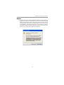
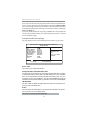
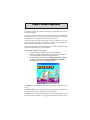
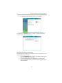
Notice:
1 Owing to Microsoft’s certifying schedule is various to every supplier, we
might have some drivers not certified yet by Microsoft. Therefore, it might
happen under Windows XP that a dialogue box (shown as below) pop out
warning you this software has not passed Windows Logo testing to verify
its compatibility with Windows XP. Please rest assured that our RD de-
partment has already tested and verified these drivers. Just click the “Con-
tinue Anyway” button and go ahead the installation.

1
Chapter 1: Introduction
Chapter 1 Introduction
Note: Hyper-Threading technology enables the operating system into thinking
it’s hooked up to two processors, allowing two threads to be run in
parallel, both on separate ‘logical’ processors within the same physical
processor.
LGA775 Socket Processor
• Supports the latest Intel
®
Core
TM
2 Quad/Intel
®
Core
TM
2 Duo/
Pentium
®
Dual-Core (E21xx series) /Celeron
®
Dual-Core/Celeron
®
4xx series processors with Hyper-Threading Technology
• Supports up to 1333 MHz Front-Side Bus
Key Features
The key features of this motherboard include:
It is a Micro ATX motherboard and has power connectors for an ATX power
supply.
It integrates the G31 Northbridge and ICH7 Southbridge that supports the Serial
ATA interface for high-performance and mainstream desktop PCs; the built-in
USB 2.0 providing higher bandwidth, implementing Universal Serial Bus Speci-
fication Revision 2.0 and is compliant with UHCI 1.1 and EHCI 1.0. It supports
High Definition Audio Codec and provides Ultra DMA 100/66 function. It has
one PCI Expressx16, one PCI Expressx1 and two 32-bit PCI slots. There is a full
set of I/O ports including two PS/2 ports for mouse and keyboard, one parallel
port, οne serial port, one VGA port, one LAN port, four back-panel USB 2.0 ports
and Audio jacks for microphone, line-in and line-out and onboard USB headers
providing extra ports by connecting the Extended USB Module to the motherboard.
This motherboard has a LGA775 socket for latest Intel
®
Core
TM
2 Quad/Intel
®
Core
TM
2 Duo/Pentium
®
Dual-Core (E21xx series)/Celeron
®
Dual-Core/
Celeron
®
4xx series processors with Hyper-Threading Technology and Front-
Side Bus (FSB) speeds up to 1333 MHz. Hyper-Threading Technology, designed
to take advantage of the multitasking features, giving you the power to do more
things at once.

2
Motherboard User’s Guide
Audio
Serial ATA
•
Four Serial ATA Connectors
• Transfer rate exceeding best ATA (3.0 Gb/s) with scalability to higher rates
• Low pin count for both host and devices
Onboard IDE channels
• One IDE Connector
• Supports PIO (Programmable Input/Output) and DMA (Direct Memory
Access) modes
• Supports IDE Ultra DMA bus mastering with transfer rates of 100/66
MB/sec
Expansion Slots
• Two 32-bit PCI slots
• One PCI Expressx16 slot
• One PCI Expressx1 slot
Memory Support
• Two 240-pin DIMM sockets for DDR2 SDRAM memory modules
• Supports DDR2 800/667 with dual-channel architecture
• Maximum installed memory is 4 GB
• System Memory Controller Support: DDR2 SDRAM with up to maxi-
mum memory of 4 GB.
• PCI Express Graphics Interface Support: One PCI Express x16 slot
• PCI Bus Interface Support: PCI Revision 2.3 Specification at 33MHz
• Integrade Serial ATA Host Controller: Independent DMA operation with
Data transfer rates up to 3.0 Gb/s
• Intgrated IDE Controller: Ultra DMA-100/66 Bus Master EIDE Control-
ler
• USB 2.0: Integrated USB 2.0 interface
• Hyper-Threading Technology
There are G31 Northbridge and ICH7 in the chipsets in accordance with an inno-
vative and scalable architecture with proven reliability and performance.
Chipset
• 5.1 Channel High Definition Audio Codec
• Exceeds Microsoft Windows Logo Program (WLP) Requirements
• ADCs support 44.1K/48K/96K/192KHz sample rate
• Power Support: Digital: 3.3V; Analog: 5.0V

3
Chapter 1: Introduction
LAN (Optional)
BIOS Firmware
This motherboard uses AMI BIOS that enables users to configure many system
features including the following:
• Power management
• Wake-up alarms
• CPU parameters and memory timing
• CPU and memory timing
The firmware can also be used to set parameters for different processor clock
sp-
Note: Hardware specifications and software items are subject to change
without notification.
Dimensions
• Micro ATX form factor of 244 x 200 mm
• Supports 10/100 Mbps Ethernet transceiver
•
Fully compliant with IEEE 802.3, IEEE 802.3u, IEEE 802.3ab
• Wake-On-LAN (WOL) by Magic Packet/ Frame/ Link Change
eeds.
Onboard I/O Ports
• Two PS/2 ports for mouse and keyboard
• One parallel port
• One serial port
• One VGA port
• Four back-panel USB2.0 ports
• Audio jacks for microphone, line-in and line-out

4
Motherboard User’s Guide
Package Contents
Your motherboard package ships with the following items:
The motherboard
The User’s Guide
One diskette drive ribbon cable (optional)
One IDE drive ribbon cable
The Software support CD
Optional Accessories
You can purchase the following optional accessories for this
motherboard.
The Extended USB module
The CNR v.90 56K Fax/Modem card
The Serial ATA cable
The Serial ATA power cable
Note: You can purchase your own optional accessories from the third party, but
please contact your local vendor on any issues of the specification and
compatibility.

5
Chapter 2: Motherboard Installation
Chapter 2 Motherboard Installation
To install this motherboard in a system, please follow these instructions in this
chapter:
Identify the motherboard components
Install a CPU
Install one or more system memory modules
Make sure all jumpers and switches are set correctly
Install this motherboard in a system chassis (case)
Connect any extension brackets or cables to headers/connectors on the
motherboard
Install peripheral devices and make the appropriate connections to head-
ers/connectors on the motherboard
Note:
1. Before installing this motherboard, make sure jumper CLR_CMOS is
under Normal setting. See this chapter for information about locating
CLR_CMOS and the setting options.
2. Never connect power to the system during installation; otherwise, it
may damage the motherboard.

6
Motherboard User’s Guide
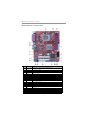
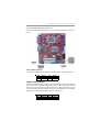
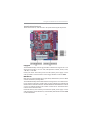
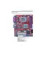
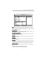
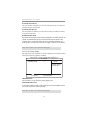
Motherboard Components
IT EM LABEL COM PONENTS
LGA775 socket for Intel
®
Core
TM
2 Quad/Intel
®
Core
TM
2 Duo/
Pentium
®
Dual-Core (E21xx series)/Celeron
®
Dual-Core/Celeron
®
4xx series CPUs
2 CPU_FAN CPU cooling fan connector
3 DDR2_1~2 240-pin DDR2 SDRAM slots
4 ATX_POWER Standard 24-pin ATX pow er connector
5SATA1~4
Serial ATA connectors
6 F_USB1~2
Front panel USB headers
7SPK
Internal speak header
8USBPWR_F
Front Panel USB Select jumper
9F_PANEL
Front Panel Switch/LED header
10 CLR_CMOS
Clear CMOS jumper
11 IDE
Primary IDE Connector
12 FDD
Floppy disk drive connector
13 CD_IN
Analog audio input connector
14 F_AUDIO
Front panel audio header
15 SPIDIFO
SPDIF out header
16 PCI1~2
32-bit add-on card slots
17 PCIE
PCI Express x1 slot
18 PCIEX16
PCI Expressx16 graphics card slot
19 USBPWR_R
Rear USB PS/2 Pow er Select Jumper
20 SYS_FAN
System cooling fan connector
21 ATX12V
Auxiliary 4-pin pow er connector
1CPU Socket

7
Chapter 2: Motherboard Installation
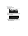
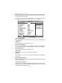
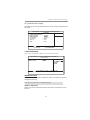
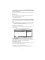
I/O Ports
The illustration below shows a side view of the built-in I/O ports on the
motherboard.
PS2 Mouse
Use the upper PS/2 port to connect a PS/2 pointing
device.
PS2 Keyboard
Use the lower PS/2 port to connect a PS/2
keyboard.
Parallel Port
(LPT1)
Use Parallel port to connect printers or other
parallel commucations devices.
Serial Port
(COM)
Use the COM port to connect serial devices such
as mice or fax/modems.
VGA Port
Use the VGA port to connect VGA devices.
LAN Port
Connect an RJ-45 jack to the LAN port to connect
your computer to the Network.
USB Ports
Use the USB ports to connect USB devices.
Audio Ports
Use these three audio jacks to connect audio
devices. The first jack is for stereo Line-In signal,
the second jack for stereo Line-Out signal, and the
third jack for Microphone.

8
Motherboard User’s Guide
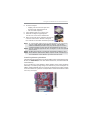
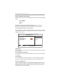
B. Unload the cap
• Use thumb & forefinger to hold the
lifting tab of the cap.
• Lift the cap up and remove the cap
completely from the socket.
C. Open the load plate
• Use thumb & forefinger to hold the
hook of the lever, pushing down and
pulling aside unlock it.
• Lift up the lever.
• Use thumb to open the load plate.
Be careful not to touch the contacts.
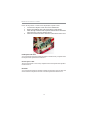
D. Install the CPU on the socket
• Orientate CPU package to the socket.
Make sure you match triangle marker
to pin 1 location.
A. Read and follow the instructions
shown on the sticker on the CPU cap.
Installing the Processor
This motherboard has a LGA775 socket for the latest Intel
®
Core
TM
2 Quad/
Intel
®
Core
TM
2 Duo/Pentium
®
Dual-Core (E21xx series)/Celeron
®
Dual-
Core/Celeron
®
4xx series processors. When choosing a processor, consider the
performance requirements of the system. Performance is based on the processor
design, the clock speed and system bus frequency of the processor, and the quan-
tity of internal cache memory and external cache memory.
CPU Installation Procedure
Follow these instructions to install the CPU:

9
Chapter 2: Motherboard Installation
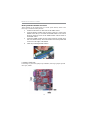
E. Close the load plate
• Slightly push down the load plate onto
the tongue side, and hook the lever.
• CPU is locked completely.
F. Apply thermal grease on top of the CPU.
G. Fasten the cooling fan supporting base
onto the CPU socket on the motherboard.
H. Make sure the CPU fan is plugged to the CPU fan
connector. Please refer to the CPU cooling fan
user’s manual for more detail installation procedure.
Installing Memory Modules
This motherboard accommodates two 240-pin DIMM sockets (Dual Inline Memory
Module) for DDR2 800/667 with dual-channel architecture, and maximum 4 GB
installed memory.
Over its predecessor, DDR-SDRAM, DDR2-SDRAM offers greater bandwith
and density in a smaller package along with a reduction in power consumption. In
addition,
DDR2-SDRAM offers new features and functions that enable a higher
clock rate and data rate operations of 800/667 MHz. DDR2 transfer 64 bits of data
twice every clock cycle.
Note 1: To achieve better airflow rates and heat dissipation, we suggest that
you use a high quality fan with 3800 rpm at least. CPU fan and
heatsink installation procedures may vary with the type of CPU fan/
heatsink supplied. The form and size of fan/heatsink may also vary.
Note 2: The fan connector supports the CPU cooling fan of 1.1A~2.2A (26.4W
max.) at +12V.
Note 3: Do Not remove the CPU cap from the socket before installing a CPU.
Note 4: Return Material Authorization (RMA) requests will be accepted only if
the motherboard comes with the cap on the LGA775 socket.

10
Motherboard User’s Guide
Memory Module Installation Procedure
These modules can be installed with up to 4 GB system memory. Refer to the
following to install the memory module.
1. Push down the latches on both sides of the DIMM socket.
2. Align the memory module with the socket. There is a notch on the
DIMM socket that you can install the DIMM module in the correct
direction. Match the cutout on the DIMM module with the notch on
the DIMM socket.
3. Install the DIMM module into the socket and press it firmly down
until it is seated correctly. The socket latches are levered upwards and
latched on to the edges of the DIMM.
4. Install any remaining DIMM modules.
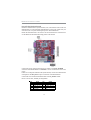
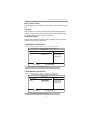
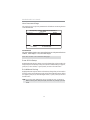
Jumper Settings
Connecting two pins with a jumper cap is SHORT; removing a jumper cap from
these pins, OPEN.

11
Chapter 2: Motherboard Installation
CLR_CMOS: Clear CMOS Jumper
Use this jumper to clear the contents of the CMOS memory. You may need to clear
the CMOS memory if the settings in the Setup Utility are incorrect and prevent
your motherboard from operating. To clear the CMOS memory, disconnect all the
power cables from the motherboard and then move the jumper cap into the CLEAR
setting for a few seconds.
Function Jumper Setting
Normal Short Pins 1-2
Clear CMOS Short Pins 2-3
Note: To avoid the system unstability after clearing CMOS, we recommend users
to enter the main BIOS setting page to “Load Optimal De-faults” and then
“Save Changes and Exit”.
CLR_CMOS
1
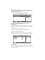
1. Make sure the power supply provides enough SB5V voltage before
selecting the SB5V function.
2. To wake up the computer by USB/PS2 KB/Mouse in S3 status, users
have to place the USBPWR_F & USBPWR_R cap onto 2-3 pin instead of 1-
2 as default, and then press into BIOS “Power Management Setup”page
to choose the functions (USB/PS2KB/MS) you want to enable.
USBPWR_F: FRONT PANEL USB POWER SELECT Jumper
USBPWR_F
1
Function Jumper Setting
VCC Short Pins 1-2
5VSB Short Pins 2-3
USBPWR_R: REAR USB PS/2 POWER SELECT Jumper
Use this jumper to set the Rear USB PS/2 Power function.
USBPWR_R
1
Function Jumper Setting
VCC Short Pins 1-2
5VSB Short Pins 2-3
Note:

12
Motherboard User’s Guide
Pin Signal Pin Signal
1 HD_LED_P(+) 2 FP PWR/SLP(+)
3 HD_LED_N(-) 4 FP PWR/SLP(-)
5 RESET_ SW_N( - ) 6 POWER_ SW_P( +)
7 RESET_ SW_P( +) 8 POWER_ SW_N( - )
9 RSVD_DNU 10 KEY
Here is a list of the F_PANEL pin assignments.
Connect the power connector from the power supply to the ATX_POWER
connector on the motherboard. The ATX12V is a +12V connector for CPU Vcore
power.
If there is a cooling fan installed in the system chassis, connect the cable from the
cooling fan to the SYS_FAN fan power connector on the motherboard.
Connect the case switches and indicator LEDs to the F_PANEL header.
Install the Motherboard
Install the motherboard in a system chassis (case). The board is a Micro ATX size
motherboard. You can install this motherboard in an ATX case. Make sure your
case has an I/O cover plate matching the ports on this motherboard.
Install the motherboard in a case. Follow the case manufacturer’s instructions to
use the hardware and internal mounting points on the chassis.

13
Chapter 2: Motherboard Installation
Pin Signal Pin Signal
1VCC2Key
3 NC 4 Signal
Connecting Optional Devices
Refer to the following for information on connecting the motherboard’s optional
devices:
SPK: Speaker Header
Connect the cable from the PC speaker to the SPK header on the motherboard.
Pin Signal Pin Signal
1SPDIFOUT2 5VA
3KEY4GDN
SPDIFO: S/PIF Out Header
S/PDIF (Sony/Plilips Digital Interface) is a standard audio transfer file format and
allows the transfer of digatal audio signals from one device to another without
having to be converted first to an analog format. Via a specific audio cable, you can
connect the SPDIFO header (S/PDIF output) on the motherboard to the S/PDIF
digital input on the external speakers or AC Decode devices.

14
Motherboard User’s Guide
F_AUDIO: Front Panel Audio Header
This header allows the user to install auxiliary front-oriented microphone and line-
out ports for easier access.
Pin Signal Pin Signal
1PORT1L 2GND
3 PORT1 R 4 PRESENCE#
5 PORT2R 6 Sense1_return
7 SENSE_ SEND 8 KEY
9PORT2L 10Sense2_return
Pin Signal Pin Signal
1 VERG_FP_USBPWR0 2 VERG_FP_USBPWR0
3 USB_FP_P0(-) 4 USB_FP_P1(-)
5 USB_FP_P0(+) 6 USB_FP_P1(+)
7 GROUND 8 GROUND
9KEY 10NC
1. Locate the F_USB1/F_USB2 header on the motherboard.
2. Plug the bracket cable onto the F_USB1/F_USB2 header.
3. Remove a slot cover from one of the expansion slots on the system
chassis. Install an extension bracket in the opening. Secure the extension
bracket to the chassis with a screw.
F_USB1~2: Front panel USB Headers
The motherboard has USB ports installed on the rear edge I/O port array. Addition-
ally, some computer cases have USB ports at the front of the case. If you have this
kind of case, use auxiliary USB headers F_USB1/F_USB2 to connect the front-
mounted ports to the motherboard.

15
Chapter 2: Motherboard Installation
Install Other Devices
Install and connect any other devices in the system following the steps below.
Floppy Disk Drive
The motherboard ships with a floppy disk drive cable that can support one or two
drives. Drives can be 3.5" or 5.25" wide, with capacities of 360 K, 720 K, 1.2 MB,
1.44 MB, or 2.88 MB.
Install your drives and connect power from the system power supply. Use the
cable provided to connect the drives to the floppy disk drive connector FDD.
IDE Devices
IDE devices include hard disk drives, high-density diskette drives, and CD-ROM
or DVD-ROM drives, among others.
The motherboard ships with an IDE cable that can support one or two IDE devices.
If you connect two devices to a single cable, you must configure one of the drivesas
Master and one of the drives as Slave. The documentation of the IDE device will tell
you how to configure the device as a Master or Slave device. The Master device
connects to the end of the cable.
Install the device(s) and connect power from the system power supply. Use the
cable provided to connect the device(s) to the Primary IDE channel connector
IDE
on the motherboard.

16
Motherboard User’s Guide
Pin Signal
1CD IN L
2GND
3GND
4CD IN R
Serial ATA Devices
The Serial ATA (Advanced Technology Attachment) is the standard interface for
the IDE hard drives, which is designed to overcome the design limitations while
enabling the storage interface to scale with the growing media rate demands of PC
platforms. It provides you a faster transfer rate of 3.0 Gb/s. If you have installed a
Serial ATA hard drive, you can connect the Serial ATA cables to the Serial ATA hard
drive or the connector on the motherboard.
On the motherboard, locate the Serial ATA connectors SATA1~4, which support
new Serial ATA devices for the highest data transfer rates, simpler disk drive cabling
and easier PC assembly.
It eliminates limitations of the current Parallel ATA interface, but maintains register
compatibility and software compatibility with Parallel ATA.
Analog Audio Input Connector
If you have installed a CD-ROM drive or DVD-ROM drive, you can connect the
drive audio cable to the onboard sound system.
When you first start up your system, the BIOS should automatically detect your
CD-ROM/DVD drive. If it doesn’t, enter the Setup Utility and configure the CD-
ROM/DVD drive that you have installed. On the motherboard, locate the 4-pin
connector CD_IN.

17
Chapter 2: Motherboard Installation
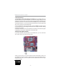
Expansion Slots
This motherboard has one PCI Ex16, one PCI Ex1 and two 32-bit PCI slots.
Page is loading ...
Page is loading ...
Page is loading ...
Page is loading ...
Page is loading ...
Page is loading ...
Page is loading ...
Page is loading ...
Page is loading ...
Page is loading ...
Page is loading ...
Page is loading ...
Page is loading ...
Page is loading ...
Page is loading ...
Page is loading ...
Page is loading ...
Page is loading ...
Page is loading ...
Page is loading ...
-
 1
1
-
 2
2
-
 3
3
-
 4
4
-
 5
5
-
 6
6
-
 7
7
-
 8
8
-
 9
9
-
 10
10
-
 11
11
-
 12
12
-
 13
13
-
 14
14
-
 15
15
-
 16
16
-
 17
17
-
 18
18
-
 19
19
-
 20
20
-
 21
21
-
 22
22
-
 23
23
-
 24
24
-
 25
25
-
 26
26
-
 27
27
-
 28
28
-
 29
29
-
 30
30
-
 31
31
-
 32
32
-
 33
33
-
 34
34
-
 35
35
-
 36
36
-
 37
37
-
 38
38
-
 39
39
-
 40
40


PC CHIPS P43G (V1.0) User guide
- Category
- Motherboards
- Type
- User guide
Ask a question and I''ll find the answer in the document
Finding information in a document is now easier with AI
Related papers
-
ECS P49G (V1.0) User manual
-
PC CHIPS P29G (V1.0) User guide
-
PC CHIPS P53G (V1.0) User manual
-
-
-
-
-
-
-