LG 26LC4* User manual

Category
LCD TVs
Type
User manual
Please read this manual carefully before operating
your set.
Retain it for future reference.
Record model number and serial number of the set.
See the label attached on the back cover and quote
this information to your dealer when you require
service.
LCD TV PLASMA TV
OWNER’S MANUAL
LCD TV MODELS
2266LLCC44
**
2266LLCC55
**
3322LLCC44
**
3322LLCC55
**
3377LLCC44
**
3377LLCC55
**
4422LLCC44
**
4422LLCC55
**
2266LLBB77** 3322LLBB77**
PLASMA TV MODELS
4422PPCC55
**
5500PPCC55
**
5500PPBB66
**
4422PPCC33
**
5500PPCC33
**
6600PPCC44
**
Trade Mark of the DVB Digital Video
Broadcasting Project (1991 to 1996)
IIDD NNuummbbeerr((ss))::
4550: 26LC45 4549: 26LC46
4548: 32LC45 4547: 32LC46
4546: 37LC45 4545: 37LC46
4544: 42LC45 4543: 42LC46
4542: 32LC55 4541: 32LC56
4540: 26LC55 4539: 37LC55
4538: 42LC55 4722: 26LB75
4918: 26LB76 4723: 32LB75
4917: 32LB76 4559: 42PC55
4555: 50PC55 4554: 42PC56
4553: 50PC56 4552: 50PB65
4892: 42PC35 4891: 50PC35
4742: 60PC45
1
ACCESSORIES
ACCESSORIES
Ensure that the following accessories are included with your TV. If an accessory is missing, please contact the
dealer where you purchased the product.
Owner's
Manual
Owner’s manual
Owner’s Manual
Batteries
OK
INPU
T
MO
DE
TV
D/A
DVD
E
X
IT
VOL PR
G
UIDE
B
A
C
K
M
ENU
RATIO
I/II
VCR
PO
WER
123
456
789
0
Q.VIEW
LIST
INDEX
SLEEP
H
O
L
D
REVEAL
?
S
U
B
T
IT
LE
TEX
T
INPUT
BRIGHT
M
U
T
E
T
V
/
R
A
D
IO
UPDATE
S
IM
P
L
IN
K
INFO i
F
A
V
T
IM
E
Remote Control
Power Cord
LLCCDD TTVV mmooddeellss
Polishing Cloth
(This feature is not available for
all models.)
Polish the screen with the cloth.
Slightly wipe stained spot on the exterior
only with the cleansing cloths for the prod-
uct exterior if there is stain or fingerprint
on surface of the exterior.
Do not wipe roughly when removing stain.
Please be cautious of that excessive power
may cause scratch or discoloration.
2-Rubber cap
Refer to p. 19
2-Wall brackets
2-eye-bolts
(This feature is not available for all models.)
Cable Management
4-bolts for stand assembly
Refer to p. 12
2266,, 3322,, 3377 oonnllyy
1-screw for stand fixing
Refer to p. 14
2266//3322LLBB77
**
oonnllyy
or
2- TV Brackets
2- Wall Brackets
2-bolts
Twister Holder
Arrange the wires with the
twister holder.
(This feature is not available for all models.)
3-bolts
Refer to p. 20
One desk-type stand fixture
protection cover
Refer to p. 20
5500PPBB66
**
,, 6600PPCC44
**
oonnllyyPPllaassmmaa TTVV mmooddeellss 6600PPCC44
**
oonnllyy
2
CONTENTS
CONTENTS
ACCESSORIES
. . . . . . . . . . . . . . . . . . . . . . . . . . . . . . . . . . . . . . . . . . . . .
1
PREPARATION
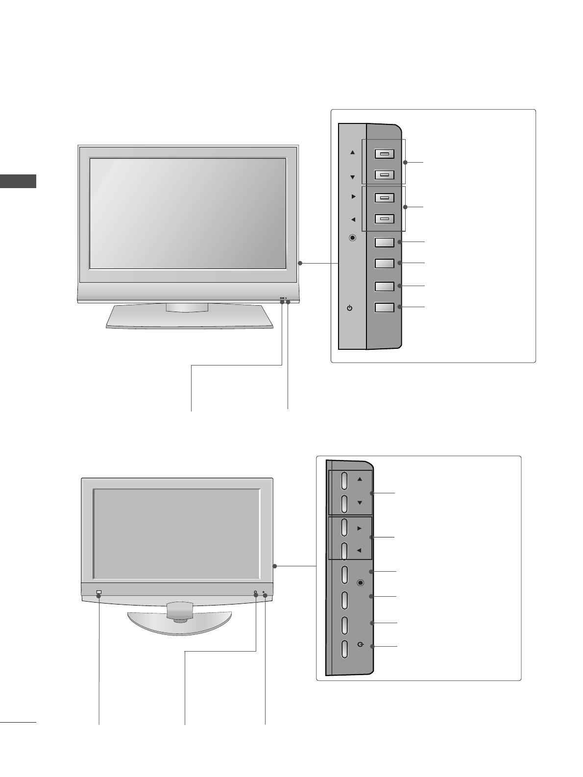
Front Panel Controls . . . . . . . . . . . . . . . . . . . . . . . . 4
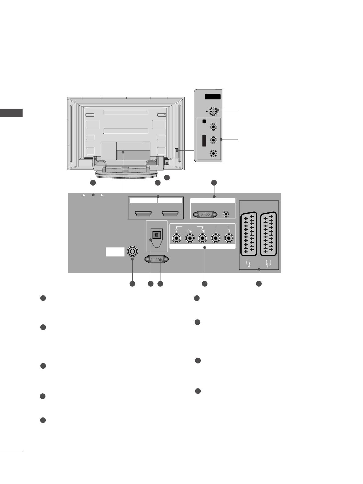
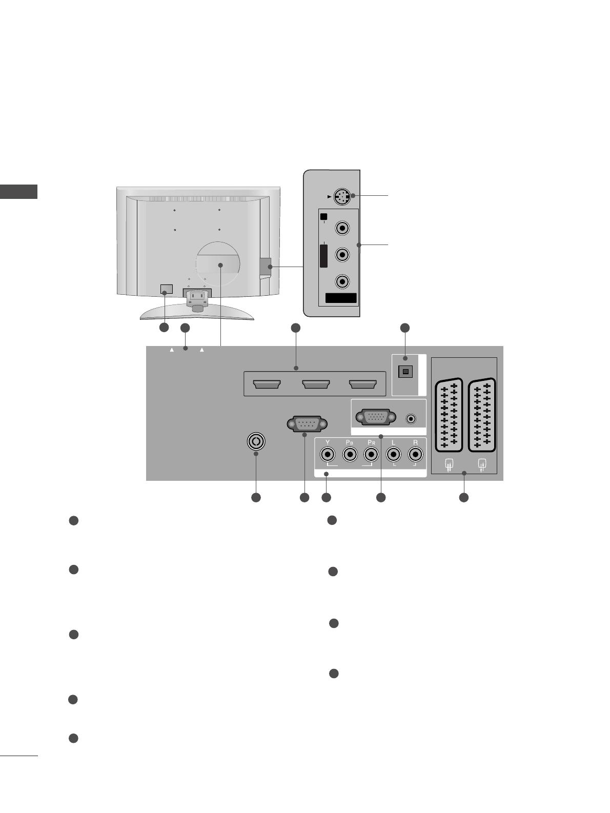
Back Panel Information . . . . . . . . . . . . . . . . . . . . . . 7
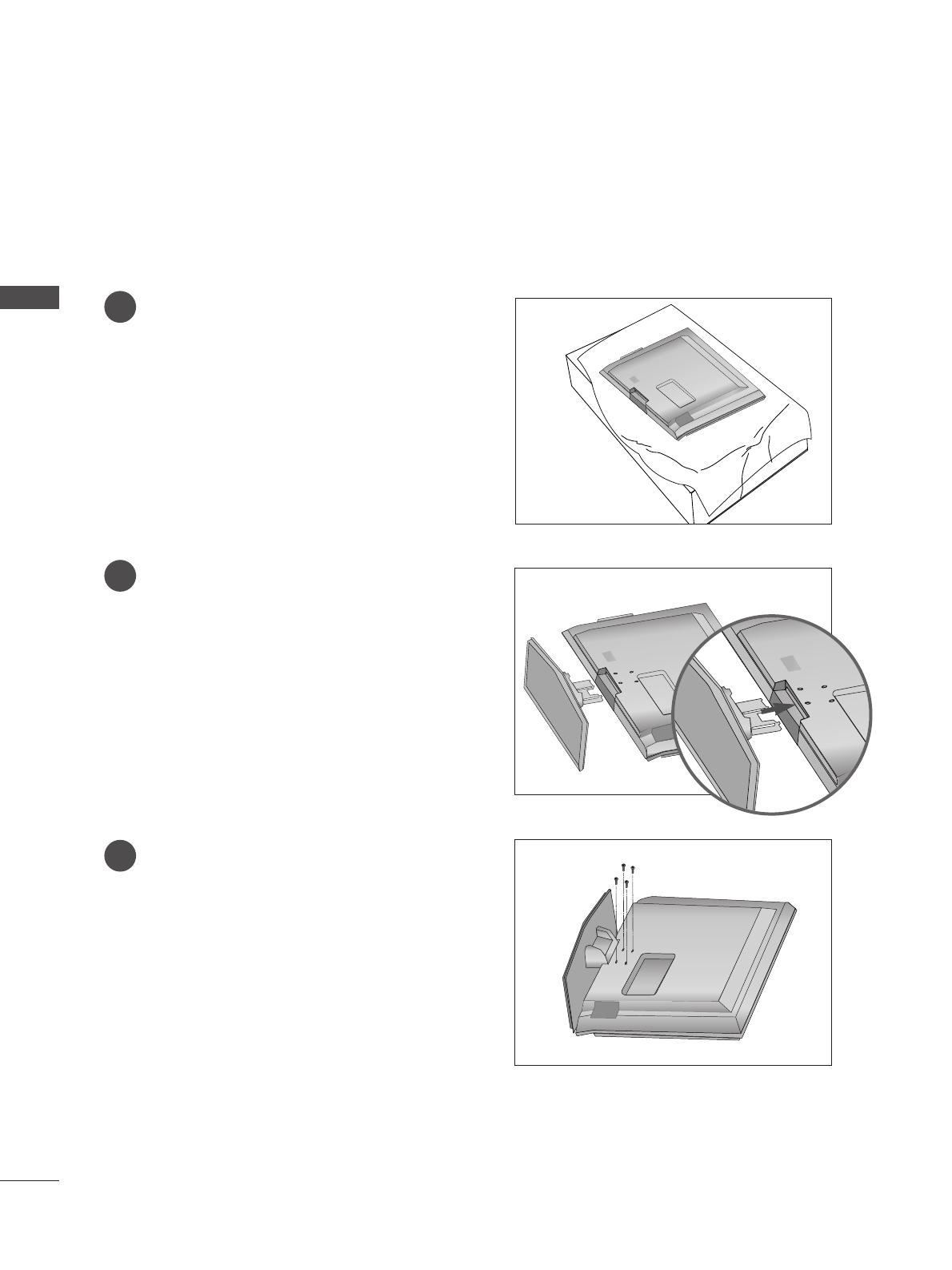
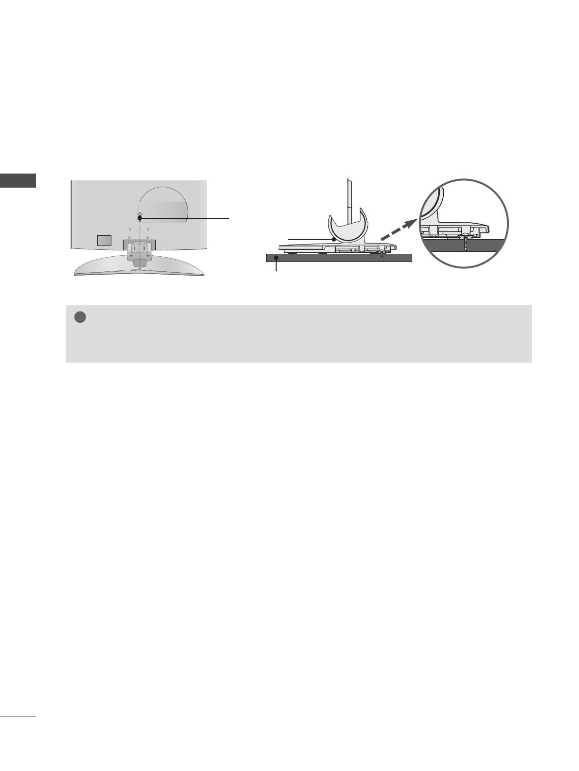
Stand installation . . . . . . . . . . . . . . . . . . . . . . . . . . . 11
Attaching the TV to a wall . . . . . . . . . . . . . . . . . . . . 13
Attaching the TV to a desk . . . . . . . . . . . . . . . . . . . 14
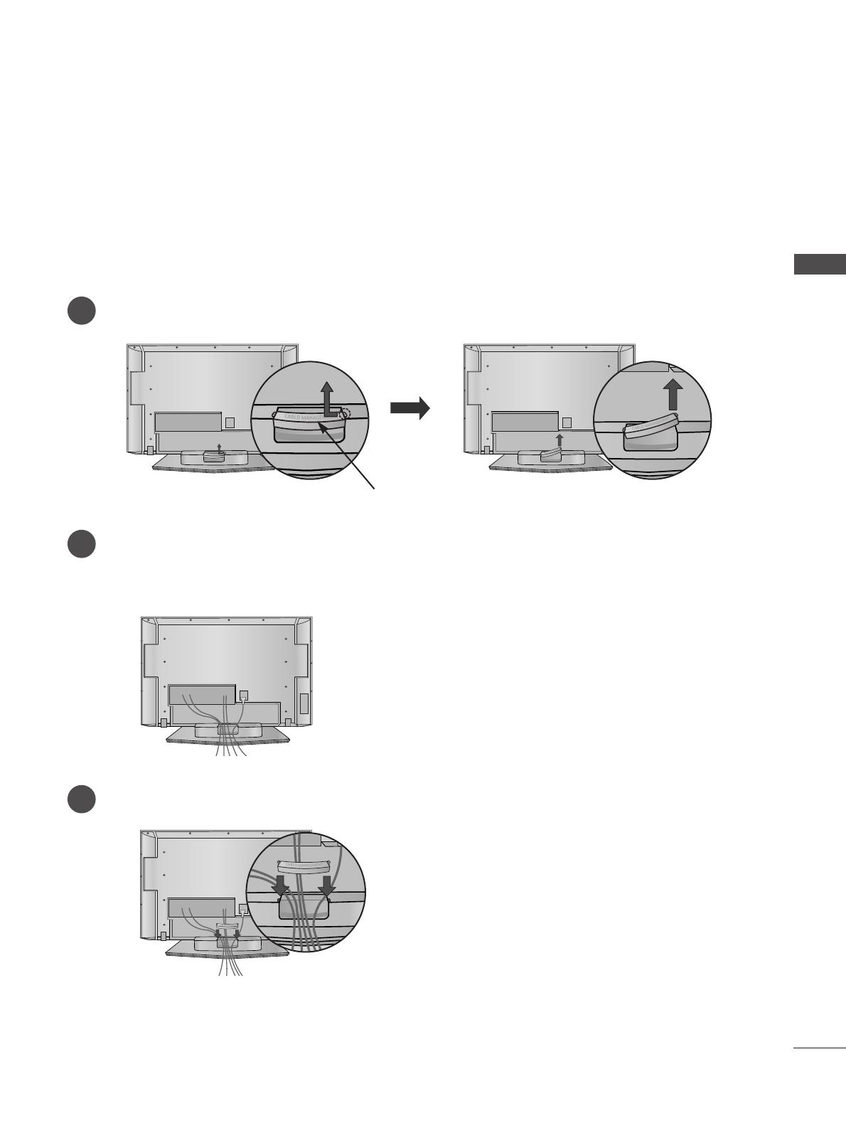
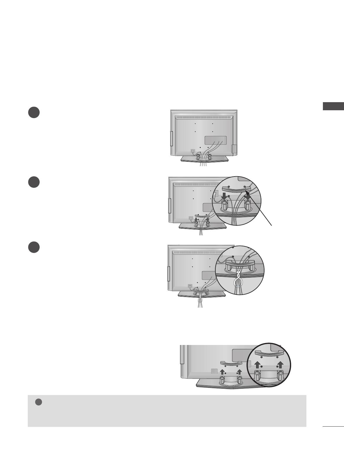
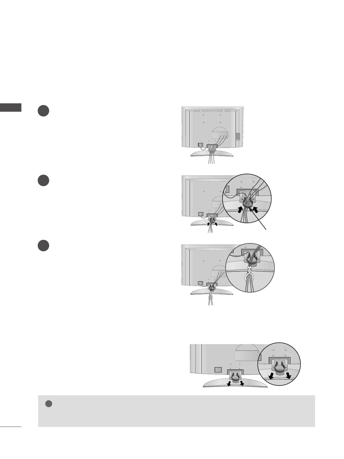
Back Cover for Wire Arrangement . . . . . . . . . . . . . 15
Desktop Pedestal Installation . . . . . . . . . . . . . . . . . 19
Wall Mount: Horizontal installation . . . . . . . . . . . . 20
Antenna Connection . . . . . . . . . . . . . . . . . . . . . . . . 21
EXTERNAL EQUIPMENT SETUP
HD Receiver Setup . . . . . . . . . . . . . . . . . . . . . . . 22
DVD Setup . . . . . . . . . . . . . . . . . . . . . . . . . . . . . . . . 25
Insertion of CI module . . . . . . . . . . . . . . . . . . . . . . 28
VCR Setup . . . . . . . . . . . . . . . . . . . . . . . . . . . . . . . . 29
Digital Audio Out Setup . . . . . . . . . . . . . . . . . . . . . 31
Other A/V Source Setup . . . . . . . . . . . . . . . . . . . . 32
PC Setup . . . . . . . . . . . . . . . . . . . . . . . . . . . . . . . . . 33
- Screen Setup for PC Mode . . . . . . . . . . . . . . . 36
WATCHING TV / PROGRAMME CONTROL
Remote Control Key Functions . . . . . . . . . . . . . . . 40
Turning on the TV . . . . . . . . . . . . . . . . . . . . . . . . . . 44
Programme Selection . . . . . . . . . . . . . . . . . . . . . . . 45
Volume Adjustment . . . . . . . . . . . . . . . . . . . . . . . . 45
On-Screen Menus Selection and Adjustment . . . . 46
Auto Programme Tuning (In Digital Mode) . . . . . . 47
Manual Programme Tuning (In Digital Mode) . . . . 48
Programme Edit (In Digital Mode) . . . . . . . . . . . . . 49
5V antenna Power (In Digital Mode only) . . . . . . . 51
Software Update (In Digital Mode only) . . . . . . . . 52
Diagnostics (In Digital Mode only) . . . . . . . . . . . . 53
CI Information (In Digital Mode only) . . . . . . . . . . 54
Auto Programme Tuning (In Analogue Mode) . . . . . 55
Manual Programme Tuning (In Analogue Mode)
. . . . . . . 56
Fine Tuning (In Analogue Mode) . . . . . . . . . . . . . . 57
Assigning a Station Name (In Analogue Mode)
. . . . . . 57
Programme Edit (In Analogue Mode)
. . . . . . . . . . . . . 58
Calling the Programme Table . . . . . . . . . . . . . . . . 60
Input Source Selection . . . . . . . . . . . . . . . . . . . . . 61
Index . . . . . . . . . . . . . . . . . . . . . . . . . . . . . . . . . . . . .61
SIMPLINK Function . . . . . . . . . . . . . . . . . . . . . . . . 62
EPG (ELECTRONIC PROGRAMME GUIDE)
(IN DIGITAL MODE)
Switch on/off EPG . . . . . . . . . . . . . . . . . . . . . . . . . 64
Select programme . . . . . . . . . . . . . . . . . . . . . . . . . . 64
Button function in NOW/NEXT guide mode
. . . . . . . . . 65
Button function in 8 days guide mode
. . . . . . . . . . . . . . 65
Button function in date change mode
. . . . . . . . . . . . . . 65
Button function in extended description box
. . . . . . . . . 66
Button function in record/remind setting mode
. . . . . . . 66
Button function in timer list mode
. . . . . . . . . . . . . . . . . 66
PICTURE CONTROL
Picture Size (Aspect Ratio) Control . . . . . . . . . . . . 67
Preset Picture Settings
- Picture Mode-Preset . . . . . . . . . . . . . . . . . . . . 69
-
Auto Colour Tone Control (Warm/Medium/Cool)
. . . . .70
Manual Picture Adjustment
- Picture Mode-User option . . . . . . . . . . . . . . . . 71
- Colour Tone - User option . . . . . . . . . . . . . . . .72
XD - Picture Improvement Technology . . . . . . . . . . . . . 73
XD Demo . . . . . . . . . . . . . . . . . . . . . . . . . . . . . . . . . 74
Advanced - Cinema . . . . . . . . . . . . . . . . . . . . . . . . . 75
Advanced - Black(Darkness) Level . . . . . . . . . . . . . 76
Picture Reset . . . . . . . . . . . . . . . . . . . . . . . . . . . . . . 77
Image Sticking Minimization(ISM) Method . . . . . . . . . . 78
Low-Power Picture Mode . . . . . . . . . . . . . . . . . . . . 79
3
CONTENTS
SOUND & LANGUAGE CONTROL
Auto Volume Leveler . . . . . . . . . . . . . . . . . . . . . . . . 80
Preset Sound Settings - Sound Mode . . . . . . . . . . 81
Sound Setting Adjustment - User Mode . . . . . . . . . . 82
Balance . . . . . . . . . . . . . . . . . . . . . . . . . . . . . . . . . . . 83
TV Speakers On/ Off Setup . . . . . . . . . . . . . . . . . . 84
Selecting digital audio out . . . . . . . . . . . . . . . . . . . 85
I/II
-
Stereo/Dual Reception (In Analogue Mode Only)
. . . . 86
-
NICAM Reception (In Analogue Mode Only) . . . . . . .
87
- Speaker Sound Output Selection . . . . . . . . . . 87
On-Screen Menu Language/Country Selection
. . . . . . . . 88
Language selection (In Digital Mode only) . . . . . . 89
TIME SETTING
Clock Setup . . . . . . . . . . . . . . . . . . . . . . . . . . . . . . . 90
Auto On/ Off Timer Setting . . . . . . . . . . . . . . . . . . 91
Auto Shut-off Setting . . . . . . . . . . . . . . . . . . . . . . . 92
Time zone Setup . . . . . . . . . . . . . . . . . . . . . . . . . . . 93
Sleep Timer Setting . . . . . . . . . . . . . . . . . . . . . . . . . 93
PARENTAL CONTROL / RATINGS
Set Password & Lock System . . . . . . . . . . . . . . . . . 94
Parental Control . . . . . . . . . . . . . . . . . . . . . . . . . . . 95
TELETEXT
Switch on/off . . . . . . . . . . . . . . . . . . . . . . . . . . . . . . 96
SIMPLE Text . . . . . . . . . . . . . . . . . . . . . . . . . . . . . . . 96
TOP Text . . . . . . . . . . . . . . . . . . . . . . . . . . . . . . . . . 96
FASTEXT . . . . . . . . . . . . . . . . . . . . . . . . . . . . . . . . . 97
Special Teletext Functions . . . . . . . . . . . . . . . . . . . . 97
DIGITAL TELETEXT
Teletext within Digital Service . . . . . . . . . . . . . . . 98
Teletext in Digital Service . . . . . . . . . . . . . . . . . . 98
APPENDIX
Troubleshooting . . . . . . . . . . . . . . . . . . . . . . . . . . . 99
Maintenance . . . . . . . . . . . . . . . . . . . . . . . . . . . . . 101
Product Specifications . . . . . . . . . . . . . . . . . . . . . 102
Programming the Remote Control . . . . . . . . . . . . 104
Programming Code . . . . . . . . . . . . . . . . . . . . . . . . 104
IR Codes . . . . . . . . . . . . . . . . . . . . . . . . . . . . . . . . 106
External Control Device Setup . . . . . . . . . . . . . . 108
4
PREPARATION
FRONT PANEL CONTROLS
PREPARATION
A
This is a simplified representation of the front panel. Here shown may be somewhat different from your TV.
A
If your product has a protection film attached, remove the film and then wipe the product with a polishing
cloth.
Plasma TV Models
42/50PC5
*
, 60PC4
*
PR
VOL
OK
MENU
INPUT
PROGRAMME Buttons
VOLUME Buttons
MENU Button
OK Button
INPUT Button
POWER Button
PR
VOL
OK
MENUMENU
INPUT
PROGRAMME Buttons
VOLUME Buttons
MENU Button
OK Button
INPUT Button
POWER Button
Power/Standby Indicator
• illuminates red in standby mode.
INPUT MENU OK VOL PR
PR
VOL
OK
MENU
INPUT
Power/Standby Indicator
• illuminates red in standby mode.
• illuminates green when the set
is switched on.
Remote Control Sensor
50PB6
*
5
PREPARATION
Plasma TV Models
42/50PC3
*
PR
VOL
OK
MENU
INPUT
Remote Control Sensor
Power/Standby Indicator
• illuminates red in standby mode.
• illuminates green when the set is switched on.
PROGRAMME Buttons
VOLUME Buttons
OK Button
MENU Button
INPUT Button
ON/OFF Button
6
PREPARATION
PREPARATION
LCD TV Models
R
Remote Control Sensor
Power/Standby Indicator
• illuminates red in standby mode.
• illuminates green when the set is switched on.
PR
VOL
OK
MENU
INPUT
/I
PROGRAMME Buttons
VOLUME Buttons
OK Button
MENU Button
INPUT Button
POWER Button
CH
VOL
PR
VOL
OK
MENU
INPUT
/I
PROGRAMME Buttons
VOLUME Buttons
OK Button
MENU Button
INPUT Button
POWER Button
Remote Control
Sensor
Intelligent Eye
Adjusts picture
according to the sur-
rounding conditions.
Power/Standby Indicator
• illuminates red in standby mode.
• illuminates green when the set is switched on.
Except 26/32LB7
*
Only 26/32LB7
*
7
PREPARATION
Plasma TV Models
PCMCIA (Personal Computer Memory Card
International Association) Card Slot
(This feature is not available in all countries.)
HDMI Input
Connect a HDMI signal to HDMI IN.
Or DVI(VIDEO)signal to HDMI/DVI port with DVI
to HDMI cable.
RGB/DVI Audio Input
Connect the monitor output from a PC to the
appropriate input port.
Antenna Input
Connect over-the-air signals to this jack.
DIGITAL AUDIO OUT OPTICAL
Connect digital audio from various types of equip-
ment.
Note: In standby mode, these ports do not work.
RS-232C IN (CONTROL & SERVICE) PORT
Connect to the RS-232C port on a PC.
Component Input
Connect a component video/audio device to
these jacks.
Euro Scart Socket (AV1/AV2)
Connect scart socket input or output from an
external device to these jacks.
Power Cord Socket
This TV operates on an AC power. The voltage is
indicated on the Specifications page. Never
attempt to operate the TV on DC power.
1
2
3
4
5
6
7
8
9
BACK PANEL INFORMATION
A
This is a simplified representation of the back panel. Here shown may be somewhat different from your TV.
Except 42/50PC3
*
AV 1 AV 2
ANTENNA
IN
VARIABLE AUDIO OUT
VIDEO
AUDIO
COMPONENT IN
AV IN 3
L/MONO
R
AUDIO
VIDEO
HDMI IN
12
RGB IN
S-VIDEO
S-Video Input
Connect S-Video out from an
S-VIDEO device.
Audio/Video Input
Connect audio/video output
from an external device to
these jacks.
AV IN 3
L/MONOMONO
R
AUDIOAUDIO
VIDEOVIDEO
S-VIDEO
AUDIO
VIDEO
AV 1 AV 2
EJECT
PCMCIA
CARD SLOT
RS-232C IN
ANTENNA
IN
AV IN 3
L/MONO
R
AUDIO
VIDEO
S-VIDEO
RGB
(PC)
AUDIO
(RGB/DVI)
RGB IN
COMPONENT IN
AUDIO
AUDIO
VIDEO
VIDEO
AV 1 AV 2
EJECT
PCMCIA
PCMCIA
CARD SLOT
CARD SLOT
RS-232C IN
(CONTROL & SERVICE)
OPTICAL
DIGITAL AUDIO
OUT
HDMI/DVI IN
12
HDMI IN
ANTENNA
IN
1 32
84 5 6 7
9
8
PREPARATION
PREPARATION
PCMCIA (Personal Computer Memory Card
International Association) Card Slot
(This feature is not available in all countries.)
HDMI Input
Connect a HDMI signal to HDMI IN.
Or DVI(VIDEO)signal to HDMI/DVI port with DVI
to HDMI cable.
RGB/DVI Audio Input
Connect the monitor output from a PC to the
appropriate input port.
Antenna Input
Connect over-the-air signals to this jack.
DIGITAL AUDIO OUT OPTICAL
Connect digital audio from various types of equip-
ment.
Note: In standby mode, these ports do not work.
RS-232C IN (CONTROL & SERVICE) PORT
Connect to the RS-232C port on a PC.
Component Input
Connect a component video/audio device to
these jacks.
Euro Scart Socket (AV1/AV2)
Connect scart socket input or output from an
external device to these jacks.
Power Cord Socket
This TV operates on an AC power. The voltage is
indicated on the Specifications page. Never
attempt to operate the TV on DC power.
1
2
3
4
5
6
7
8
9
S-Video Input
Connect S-Video out from an
S-VIDEO device.
Audio/Video Input
Connect audio/video output
from an external device to
these jacks.
AV IN 3
L/MONOMONO
R
AUDIOAUDIO
VIDEOVIDEO
S-VIDEO
AUDIO
VIDEO
AV 1 AV 2
EJECT
PCMCIA
CARD SLOT
RS-232C IN
ANTENNA
IN
RGB
(PC)
AUDIO
(RGB/DVI)
RGB IN
COMPONENT IN
AUDIO
UDIO
VIDEO
VIDEO
AV 1 AV 2
EJECT
EJECT
PCMCIA
PCMCIA
CARD SLO
CARD SLO
T
RS-232C IN
(CONTROL & SERVICE)
OPTICAL
DIGITAL AUDIO
OUT
HDMI/DVI IN
12
HDMI IN
ANTENNA
IN
1 3
84 5 6 7
Only 42/50PC3
*
9
2
9
PREPARATION
LCD TV Models
PCMCIA (Personal Computer Memory Card
International Association) Card Slot
(This feature is not available in all countries.)
HDMI Input
Connect a HDMI signal to HDMI IN.
Or DVI(VIDEO)signal to HDMI/DVI port with DVI
to HDMI cable.
RGB/DVI Audio Input
Connect the monitor output from a PC to the
appropriate input port.
Antenna Input
Connect over-the-air signals to this jack.
DIGITAL AUDIO OUT OPTICAL
Connect digital audio from various types of equip-
ment.
Note: In standby mode, these ports do not work.
RS-232C IN (CONTROL & SERVICE) PORT
Connect to the RS-232C port on a PC.
Component Input
Connect a component video/audio device to
these jacks.
Euro Scart Socket (AV1/AV2)
Connect scart socket input or output from an
external device to these jacks.
Power Cord Socket
This TV operates on an AC power. The voltage is
indicated on the Specifications page. Never
attempt to operate the TV on DC power.
1
2
3
4
5
6
7
8
9
Except 26/32LB7
*
AV IN 3
L/MONO
R
AUDIO
VIDEO
S-VIDEO
HDMI IN
12
VARIABLE
AUDIO OUT
RGB IN
COMPONENT IN
AUDIO
VIDEO
AV 1 AV 2
ANTENNA
IN
AV 3
L/MONO
R
AUDIO
VIDEO
S-VIDEO
AUDIO IN
(RGB/DVI)
RGB
(PC)
RGB IN
COMPONENT IN
AUDIO
AUDIO
VIDEO
VIDEO
AV 1 AV 2
ANTENNA
IN
EJECT
EJECT
HDMI/DVI IN 1
HDMI/DVI IN 1
HDMI IN 2
HDMI IN 2
PCMCIA
PCMCIA
CARD SLOT
CARD SLOT
RS-232C IN
(CONTROL & SERVICE)
OPTICAL
DIGITAL AUDIO OUT
1 2 3
S-Video Input
Connect S-Video out from an S-
VIDEO device.
Audio/Video Input
Connect audio/video output from
an external device to these jacks.
AV IN 3
L/MONO
R
AUDIOAUDIO
VIDEOVIDEO
S-VIDEO
HDMI IN
12
VARIABLE
AUDIO OUT
RGB IN
COMPONENT IN
AUDIO
VIDEO
AV 1 AV 2
ANTENNA
IN
84 5 6 7
9
10
PREPARATION
PREPARATION
PCMCIA (Personal Computer Memory Card
International Association) Card Slot
(This feature is not available in all countries.)
HDMI Input
Connect a HDMI signal to HDMI IN.
Or DVI(VIDEO)signal to HDMI/DVI port with DVI
to HDMI cable.
DIGITAL AUDIO OUT OPTICAL
Connect digital audio from various types of equip-
ment.
Note: In standby mode, these ports do not work.
Antenna Input
Connect over-the-air signals to this jack.
RS-232C IN (CONTROL & SERVICE) PORT
Connect to the RS-232C port on a PC.
Component Input
Connect a component video/audio device to
these jacks.
RGB/DVI Audio Input
Connect the monitor output from a PC to the
appropriate input port.
Euro Scart Socket (AV1/AV2)
Connect scart socket input or output from an
external device to these jacks.
Power Cord Socket
This TV operates on an AC power. The voltage is
indicated on the Specifications page. Never
attempt to operate the TV on DC power.
1
2
3
4
5
6
7
8
9
Only 26/32LB7
*
AV IN 2
L/MONO
R
AUDIO
VIDEO
USB IN
AV 3
L/MONO
R
AUDIO
VIDEO
S-VIDEO
AUDIO IN
(RGB/DVI)
RGB
(PC)
RGB IN
COMPONENT IN
AUDIO
UDIO
VIDEO
VIDEO
AV 1 AV 2
ANTENNA IN
EJECT
EJECT
HDMI/D
HDMI/D
VI IN 1 HDMI IN 2
HDMI IN 2
HDMI IN 3
HDMI IN 3
PCMCIA
PCMCIA
CARD SLO
CARD SLO
T
RS-232C IN
(CONTROL & SERVICE)
OPTICAL
DIGITAL AUDIO OUT
1 2 3
S-Video Input
Connect S-Video out from an S-
VIDEO device.
Audio/Video Input
Connect audio/video output from
an external device to these jacks.
AV IN 3
L/MONO
R
AUDIOAUDIO
VIDEOVIDEO
S-VIDEO
HDMI IN
12
VARIABLE
AUDIO OUT
RGB IN
COMPONENT IN
AUDIO
VIDEO
AV 1 AV 2
ANTENNA
IN
84 5 6 7
9
11
PREPARATION
STAND INSTALLATION
(
Only 42/50PC3
*)
Figures shown here may be slightly different from your set.
WWhheenn cclloossiinngg tthhee ssttaanndd ffoorr ssttoorraaggee
First remove the screws in the holes (B)on the bottom of the
stand.And then pull two Hooks (D)of the stand bottom and
fold the stand into the back of the set.
After folding,push two Locks (A)of the stand bottom outward.
NOTE
!
Place the set with the screen facing down on a cushion or soft cloth as shown in Figures 1.
Before unfolding the stand,please make sure two locks (A)on the bottom of the stand push outward.
Pull the stand out as shown above in Figures 2 ~ 3.
After unfolding the stand,please insert and tighten the screws in the holes (B)on the bottom of the stand.
When connecting cables to the set,Do not disengage the lock (C).
This may cause the set to fall,causing serious bodily injury and serious damage to the set.
A
C
B
1
2
3
4
This feature is not available for all models.
A
D
B
12
PREPARATION
PREPARATION
1
2
3
Carefully place the product screen side down on
a cushioned surface that will protect product and
screen from damage.
Assemble the product stand with the product as
shown.
Install the 4 bolts securely, in the back of the
product in the holes provided.
STAND INSTALLATION (Only 26, 32, 37 inch LCD TV Models)
13
PREPARATION
ATTACHING THE TV TO A WALL
Plasma TV models LCD TV models
2
1
This feature is not available for all models.
A
Set it up close to the wall so the product doesn’t fall over when it is pushed backwards.
A
The instructions shown below is a safer way to set up the product, which is to fix it on the wall so the
product doesn’t fall over when it is pulled in the forward direction. It will prevent the product from
falling for-ward and hurting people. It will also prevent the product from damage caused by fall. Please
make sure that children don’t climb on or hang from the product.
NOTE
!
G
When moving the product to another place undo the ropes first.
G
Use a product holder or a cabinet that is big and strong enough for the size and weight of the product.
G
To use the product safely make sure that the height of the bracket that is mounted on the wall is same
as that of the product.
2
3
1
1
2
Use the eye-bolts or TV brackets/bolts to fix the product to the wall as shown in the picture.
(If your product has the bolts in the eye-bolts position before inserting the eye-bolts, loosen the bolts.)
* Insert the eye-bolts or TV brackets/bolts and tighten them securely in the upper holes.
Secure the wall brackets with the bolts (not provided as parts of the product, must purchase separately) on
the wall. Match the height of the bracket that is mounted on the wall.
3
Use a sturdy rope (not provided as parts of the product, must purchase separately) to tie the
product. It is safer to tie the rope so it becomes horizontal between the wall and the product.
14
PREPARATION
PREPARATION
ATTACHING THE TV TO A DESK (Only 26/32LB7
*
model)
WARNING
!
GG
This apparatus must be securely attached to the floor/wall per installation instructions.
Tipping, shaking, or rocking the machine may cause injury.
1-screw
Stand
Desk
The TV must be attached to desk so it cannot be pulled in a forward/backward direction, potentially causing
injury or damaging the product. Use only an attached screw.
15
PREPARATION
Plasma TV models
(Except 42/50PC3
*
)
Connect the cables as necessary.
To connect an additional equipment, see the
EExxtteerrnnaall eeqquuiippmmeenntt SSeettuupp
section.
Reinstall the
CCAABBLLEE MMAANNAAGGEEMMEENNTT
as shown.
2
1
3
CABLE MANAGEMENT
Hold the
CCAABBLLEE MMAANNAAGGEEMMEENNTT
with hands and push it as shown.
BACK COVER FOR WIRE ARRANGEMENT
16
PREPARATION
Plasma TV models
Arrange the cables as shown picture.
Hold the
CCAABBLLEE MMAANNAAGGEEMMEENNTT
with both
hands and push it as shown.
Connect the cables as necessary.
To connect an additional equipment, see the
EExxtteerrnnaall eeqquuiippmmeenntt SSeettuupp
section.
Reinstall the
CCAABBLLEE MMAANNAAGGEEMMEENNTT
as
shown.
1
2
3
CABLE MANAGEMENT
Only 42PC3
*
Only 50PC3
*
17
PREPARATION
LCD TV models
(Except 26/32LB7
*
)
Connect the cables as necessary.
To connect an additional equipment, see the
EExxtteerrnnaall eeqquuiippmmeenntt SSeettuupp
section.
1
Install the
CCAABBLLEE MMAANNAAGGEEMMEENNTT
as shown.
2
Bundle the cables using the supplied twister
holder. (This feature is not available for all
models.)
3
Hold the
CCAABBLLEE MMAANNAAGGEEMMEENNTT
with both
hands and pull it upward.
NOTE
!
GG
Do not hold the CABLE MANAGEMENT when moving the product.
- If the product is dropped, you may be injured or the product may be broken.
How to remove the cable management
CABLE MANAGEMENT
18
PREPARATION
PREPARATION
LCD TV model
(Only 26/32LB7
*
)
Connect the cables as necessary.
To connect an additional equipment, see the
EExxtteerrnnaall eeqquuiippmmeenntt SSeettuupp
section.
Install the
CCAABBLLEE MMAANNAAGGEEMMEENNTT
as shown.
(Insert it as pushing the loops on the both
sides of the cable management.)
Bundle the cables using the supplied twist
holder. (This feature is not available for all
models.)
Hold the
CCAABBLLEE MMAANNAAGGEEMMEENNTT
with both
hands and pull it out.
(Pull it out as holding the loops on the both sides of
the cable management.)
NOTE
!
GG
Do not hold the CABLE MANAGEMENT when moving the product.
- If the product is dropped, you may be injured or the product may be broken.
How to remove the cable management
CABLE MANAGEMENT
1
2
3
  • Page 1 1
  • Page 2 2
  • Page 3 3
  • Page 4 4
  • Page 5 5
  • Page 6 6
  • Page 7 7
  • Page 8 8
  • Page 9 9
  • Page 10 10
  • Page 11 11
  • Page 12 12
  • Page 13 13
  • Page 14 14
  • Page 15 15
  • Page 16 16
  • Page 17 17
  • Page 18 18
  • Page 19 19
  • Page 20 20
  • Page 21 21
  • Page 22 22
  • Page 23 23
  • Page 24 24
  • Page 25 25
  • Page 26 26
  • Page 27 27
  • Page 28 28
  • Page 29 29
  • Page 30 30
  • Page 31 31
  • Page 32 32
  • Page 33 33
  • Page 34 34
  • Page 35 35
  • Page 36 36
  • Page 37 37
  • Page 38 38
  • Page 39 39
  • Page 40 40
  • Page 41 41
  • Page 42 42
  • Page 43 43
  • Page 44 44
  • Page 45 45
  • Page 46 46
  • Page 47 47
  • Page 48 48
  • Page 49 49
  • Page 50 50
  • Page 51 51
  • Page 52 52
  • Page 53 53
  • Page 54 54
  • Page 55 55
  • Page 56 56
  • Page 57 57
  • Page 58 58
  • Page 59 59
  • Page 60 60
  • Page 61 61
  • Page 62 62
  • Page 63 63
  • Page 64 64
  • Page 65 65
  • Page 66 66
  • Page 67 67
  • Page 68 68
  • Page 69 69
  • Page 70 70
  • Page 71 71
  • Page 72 72
  • Page 73 73
  • Page 74 74
  • Page 75 75
  • Page 76 76
  • Page 77 77
  • Page 78 78
  • Page 79 79
  • Page 80 80
  • Page 81 81
  • Page 82 82
  • Page 83 83
  • Page 84 84
  • Page 85 85
  • Page 86 86
  • Page 87 87
  • Page 88 88
  • Page 89 89
  • Page 90 90
  • Page 91 91
  • Page 92 92
  • Page 93 93
  • Page 94 94
  • Page 95 95
  • Page 96 96
  • Page 97 97
  • Page 98 98
  • Page 99 99
  • Page 100 100
  • Page 101 101
  • Page 102 102
  • Page 103 103
  • Page 104 104
  • Page 105 105
  • Page 106 106
  • Page 107 107
  • Page 108 108
  • Page 109 109
  • Page 110 110
  • Page 111 111
  • Page 112 112
  • Page 113 113
  • Page 114 114
  • Page 115 115
  • Page 116 116
  • Page 117 117
  • Page 118 118
  • Page 119 119
  • Page 120 120

LG 26LC4* User manual

Category
LCD TVs
Type
User manual

Ask a question and I''ll find the answer in the document

Finding information in a document is now easier with AI