Emerson 7003M User manual
- Category
- Oxygen Equipment
- Type
- User manual
This manual is also suitable for

Operator Manual
748223-K
June 2002
http://www.processanalytic.com
Model 7003M
Percent Oxygen Analyzer

Emerson Process Management
Rosemount Analytical Inc.
Process Analytic Division
1201 N. Main St.
Orrville, OH 44667-0901
T (330) 682-9010
F (330) 684-4434
e-mail: [email protected]
http://www.processanalytic.com
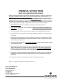
ESSENTIAL INSTRUCTIONS
READ THIS PAGE BEFORE PROCEEDING!
Rosemount Analytical designs, manufactures and tests its products to meet many national and
international standards. Because these instruments are sophisticated technical products, you
MUST properly install, use, and maintain them to ensure they continue to operate within their
normal specifications. The following instructions MUST be adhered to and integrated into your
safety program when installing, using, and maintaining Rosemount Analytical products. Failure to
follow the proper instructions may cause any one of the following situations to occur: Loss of life;
personal injury; property damage; damage to this instrument; and warranty invalidation.
• Read all instructions prior to installing, operating, and servicing the product.
• If you do not understand any of the instructions, contact your Rosemount Analytical rep-
resentative for clarification.
• Follow all warnings, cautions, and instructions marked on and supplied with the product.
• Inform and educate your personnel in the proper installation, operation, and maintenance of
the product.
• Install your equipment as specified in the Installation Instructions of the appropriate Instruc-
tion Manual and per applicable local and national codes. Connect all products to the proper
electrical and pressure sources.
• To ensure proper performance, use qualified personnel to install, operate, update, program,
and maintain the product.
• When replacement parts are required, ensure that qualified people use replacement parts
specified by Rosemount. Unauthorized parts and procedures can affect the product’s per-
formance, place the safe operation of your process at risk, and VOID YOUR WARRANTY.
Look-alike substitutions may result in fire, electrical hazards, or improper operation.
• Ensure that all equipment doors are closed and protective covers are in place, except when
maintenance is being performed by qualified persons, to prevent electrical shock and per-
sonal injury.
The information contained in this document is subject to change without notice.
Ryton® is a registered trademark of Phillips Petroleum Co.

Operator Manual
748223-K
June 2002
Rosemount Analytical Inc. A Division of Emerson Process Management Contents i
Model 7003M
TABLE OF CONTENTS
PREFACE...........................................................................................................................................P-1
Definitions ...........................................................................................................................................P-1
Safety Summary .................................................................................................................................P-2
Documentation....................................................................................................................................P-5
Compliances .......................................................................................................................................P-5
1-0 DESCRIPTION AND SPECIFICATIONS..............................................................................1-1
1-1 Overview................................................................................................................................1-1
1-2 Principle of Measurement......................................................................................................1-1
1-3 Sensors..................................................................................................................................1-1
1-4 Conditions Affecting Measurement .......................................................................................1-2
a. Gas Composition.............................................................................................................1-2
b. Sample and Cal Gas Pressures......................................................................................1-2
c. Environmental Factors ....................................................................................................1-2
1-5 Features.................................................................................................................................1-3
1-6 Specifications ........................................................................................................................1-4
a. Performance....................................................................................................................1-4
b. Physical...........................................................................................................................1-4
c. Electrical..........................................................................................................................1-5
d. Sensors ...........................................................................................................................1-5
2-0 INSTALLATION ....................................................................................................................2-1
2-1 Unpacking..............................................................................................................................2-1
2-2 Storage ..................................................................................................................................2-1
2-3 Analyzer Installation ..............................................................................................................2-1
2-4 Sensor Installation .................................................................................................................2-1
a. Analyzer/Sensor Jumper Configuration ..........................................................................2-1
2-5 Electrical Connections ...........................................................................................................2-3
a. Sensor Cable ..................................................................................................................2-4
b. Power Connections.........................................................................................................2-4
c. Current Output Connections ...........................................................................................2-6
d. Voltage Output Connections ...........................................................................................2-6
2-6 Relay Contacts for Alarms or ON/OFF-Controls ...................................................................2-8
3-0 OPERATION .........................................................................................................................3-1
3-1 Overview................................................................................................................................3-1
3-2 Keypad Operation..................................................................................................................3-1
a. Single and Double Keystroke..........................................................................................3-3
b. Display Prompts ..............................................................................................................3-4
c. Error Messages...............................................................................................................3-6
d. Automatic Return to RUN Mode .....................................................................................3-7
e. Preventing Unauthorized Access....................................................................................3-7
f. Sensor Equilibrium..........................................................................................................3-7
3-3 Start-Up .................................................................................................................................3-8
a. Initial Power-Up...............................................................................................................3-8
b. System Restart................................................................................................................3-9
c. Automatic Restart - Due to Power Failure ......................................................................3-9
d. Manual Restart................................................................................................................3-9

Operator Manual
748223-K
June 2002
ii Contents Rosemount Analytical Inc. A Division of Emerson Process Management
Model 7003M
3-4 Run Mode ..............................................................................................................................3-10
a. Display Oxygen Concentration/Sensor Temperature .....................................................3-10
b. Acknowledge Alarms ......................................................................................................3-10
c. Access Other Modes.......................................................................................................3-10
3-5 Setup Mode ...........................................................................................................................3-11
a. Security Code..................................................................................................................3-13
b. Current Output Range - 0-20mA or 4-20mA................................................................3-13
c. Range Endpoint Adjustments .........................................................................................3-13
d. Zero Offset Adjustment ...................................................................................................3-15
3-6 Alarm Mode vs. ON/OFF-Control Mode ................................................................................3-16
a. Relay Configured as Alarm .............................................................................................3-16
b. Relay Configured as ON/OFF-Controller ........................................................................3-16
c. Relay Contacts................................................................................................................3-18
d. Fail Safe Operation .........................................................................................................3-18
e. Relay Reset Upon Fatal Error.........................................................................................3-18
f. Pressure Effects on Alarms ............................................................................................3-18
g. Setting Alarm and ON/OFF-Controller Relays................................................................3-18
h. Setting Alarm Setpoints ..................................................................................................3-18
i. Setting Alarm ON and OFF Levels .................................................................................3-19
4-0 CALIBRATION AND ADJUSTMENTS.................................................................................4-1
4-1 Frequency of Calibration .......................................................................................................4-1
4-2 Calibration mode ...................................................................................................................4-1
a. Zero Calibration...............................................................................................................4-1
b. Span Calibration..............................................................................................................4-1
c. Pressure Compensation - Correction for Constant Pressure Differences ......................4-4
4-3 Hold Mode .............................................................................................................................4-5
4-4 Diagnostics Mode ..................................................................................................................4-8
a. Raw Sensor Voltage .......................................................................................................4-8
b. Test Current Output ........................................................................................................4-8
c. Linearizing Current Output..............................................................................................4-8
d. Test Alarm Relays...........................................................................................................4-10
4-5 Adjustments And Settings .....................................................................................................4-10
5-0 THEORY................................................................................................................................5-1
5-1 Principles Of Operation .........................................................................................................5-1
a. Electrochemical Theory ..................................................................................................5-1
5-2 Effects of Sample Conditions ................................................................................................5-1
a. Barometric Pressure .......................................................................................................5-1
b. Humidity ..........................................................................................................................5-1
c. Sample Temperature ......................................................................................................5-1
d. Interfering Gases.............................................................................................................5-2
5-3 Circuit Descriptions................................................................................................................5-2
a. Signal Board....................................................................................................................5-2
b. Power Supply Board .......................................................................................................5-2
c. Microprocessor Board.....................................................................................................5-2
d. Alarm Circuits..................................................................................................................5-2
6-0 ROUTINE SERVICING AND TROUBLESHOOTING...........................................................6-1
6-1 Routine Servicing ..................................................................................................................6-1
6-2 Troubleshooting.....................................................................................................................6-1
a. Symptoms .......................................................................................................................6-1

Operator Manual
748223-K
June 2002
Rosemount Analytical Inc. A Division of Emerson Process Management Contents iii
Model 7003M
7-0 REPLACEMENT PARTS ......................................................................................................7-1
7-1 Circuit Board Replacement Policy .........................................................................................7-1
7-2 Matrix .....................................................................................................................................7-1
7-3 Replacement Parts - Model 7003M.......................................................................................7-2
7-4 Replacement Parts - Sensors................................................................................................7-3
a. Rechargeable Sensors ...................................................................................................7-3
b. Disposable Sensors ........................................................................................................7-4
8-0 RETURN OF MATERIAL ......................................................................................................8-1
8-1 Return Of Material .................................................................................................................8-1
8-2 Customer Service ..................................................................................................................8-1
8-3 Training..................................................................................................................................8-1
LIST OF ILLUSTRATIONS
Figure 2-1. Sensor Ordering Matrix.......................................................................................... 2-2
Figure 2-2. Model 7003M Rear Panel Connections................................................................. 2-3
Figure 2-3. Power Jumpers and Fuses .................................................................................... 2-5
Figure 2-4. Current Output Connections .................................................................................. 2-7
Figure 3-1. Model 7003M Front Panel Controls and Indicators ............................................... 3-1
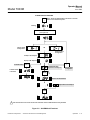
Figure 3-2. Model 7003M Operation Flow Diagram................................................................. 3-2
Figure 3-3. SETUP Mode Flowchart ...................................................................................... 3-12
Figure 3-4. Security Access Routine Flowchart ..................................................................... 3-14
Figure 3-5. ALARM Mode Flowchart...................................................................................... 3-17
Figure 3-6. Action of Alarm Relay ON and OFF Setpoints .................................................... 3-19
Figure 4-1. CALIBRATION Mode and PRESSURE COMPENSATION Flowchart.................. 4-3
Figure 4-2. HOLD and DIAGNOSTICS Modes Flowchart ....................................................... 4-7

Operator Manual
748223-K
June 2002
iv Contents Rosemount Analytical Inc. A Division of Emerson Process Management
Model 7003M
LIST OF TABLES
Table 2-1. Sensor Cables ....................................................................................................... 2-4
Table 2-2. Analyzer Cable Connections ................................................................................. 2-4
Table 3-1. Key Functions ........................................................................................................ 3-3
Table 3-2. Display Indicators .................................................................................................. 3-3
Table 3-3. Security Access Prompts and Responses............................................................. 3-4
Table 3-4. Alarm Settings Prompts and Responses............................................................... 3-4
Table 3-5. Calibration Prompts and Responses ..................................................................... 3-4
Table 3-6. System Setup Prompts and Responses................................................................ 3-4
Table 3-7. System Hold and Diagnostics Codes .................................................................... 3-5
Table 3-8. Data Displayed in DIAGNOSTICS Mode............................................................... 3-5
Table 3-9. Miscellaneous Prompts and Responses ............................................................... 3-5
Table 3-10. Power ON, Reset Diagnostics Errors (Fatal Errors ............................................... 3-6
Table 3-11. RUN Mode Errors (Non-Fatal Errors ..................................................................... 3-6
Table 3-12. Signal Board Errors ............................................................................................... 3-6
Table 3-13. Microprocessor Errors That Reset The System .................................................... 3-6
Table 3-14. Default Settings at Power-Up ................................................................................ 3-8
Table 3-15. RUN Mode Key Functions ................................................................................... 3-10
Table 3-16. SETUP Mode Key Functions .............................................................................. 3-11
Table 3-17. ALARM Mode Key Functions.............................................................................. 3-16
Table 3-18. Alarm Relay Contact Positions/Terminal Locations............................................. 3-18
Table 4-1. CALIBRATION Mode Key Functions........................................................................1
Table 4-2. Composition of Dry Atmospheric Air...................................................................... 4-2
Table 4-3. Composition of Humid Atmospheric Air................................................................. 4-2
Table 4-4. Barometric Pressure Effect on Apparent Oxygen Concentration ..............................4
Table 4-5. PRESSURE COMPENSATION Mode Key Functions..............................................4
Table 4-6. HOLD Mode Key Functions ......................................................................................5
Table 4-7. Caret Readings...................................................................................................... 4-6
Table 4-8. DIAGNOSTICS Mode Key Functions ................................................................... 4-8
LIST OF DRAWINGS
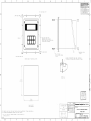
652542 Outline and Mounting – Panel Mount
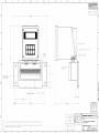
652543 Outline and Mounting – Wall Mount
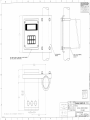
652544 Outline and Mounting – Pipe Mount
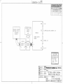
652682 Pictorial Wiring Diagram
652683 Interconnect Diagram
652699 Installation Drawing

Operator Manual
748223-K
June 2002
Rosemount Analytical Inc. A Division of Emerson Process Management Preface P-1
Model 7003M
PREFACE
The purpose of this manual is to provide information concerning the components,
functions, installation and maintenance of the Model 7003M Percent Oxygen Analyzer
Some sections may describe equipment not used in your configuration. The user should
become thoroughly familiar with the operation of this module before operating it. Read
this instruction manual completely.
DEFINITIONS
The following definitions apply to DANGERS, WARNINGS, CAUTIONS and NOTES found throughout
this publication.
DANGER .
Highlights the presence of a hazard which will cause severe personal injury, death, or substantial
property damage if the warning is ignored.
WARNING .
Highlights an operation or maintenance procedure, practice, condition, statement, etc. If not
strictly observed, could result in injury, death, or long-term health hazards of personnel.
CAUTION.
Highlights an operation or maintenance procedure, practice, condition, statement, etc. If not
strictly observed, could result in damage to or destruction of equipment, or loss of effectiveness.
NOTE
Highlights an essential operating procedure,
condition or statement.

Operator Manual
748223-K
June 2002
P-2 Preface Rosemount Analytical Inc. A Division of Emerson Process Management
Model 7003M
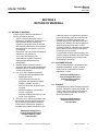
SAFETY SUMMARY
If this equipment is used in a manner not specified in these instructions, protective systems may be
impaired.
AUTHORIZED PERSONNEL
To avoid explosion, loss of life, personal injury and damage to this equipment and on-site property,
all personnel authorized to install, operate and service the this equipment should be thoroughly
familiar with and strictly follow the instructions in this manual. SAVE THESE INSTRUCTIONS.
DANGER.
ELECTRICAL SHOCK HAZARD
Do not operate without doors and covers secure. Servicing requires access to live parts which can
cause death or serious injury. Refer servicing to qualified personnel.
For safety and proper performance this instrument must be connected to a properly grounded
three-wire source of power.
Relay contacts wired to separate power sources must be disconnected before servicing.
This instrument was shipped from the factory set up to operate on either 115 VAC 50/60 Hz, or 230
VAC 50/60 Hz, as specified by sales order. Verification that this voltage is proper for the installation
is the responsibility of the purchaser. See Section 2-5b on page 2-4.
WARNING .
OXYGEN LEVEL WILL NOT BE MONITORED
The instrument will not return automatically to the RUN mode from HOLD or DIAGNOSTICS modes.
Operator must manually return instrument to RUN mode to continue monitoring oxygen.
WARNING.
ERRONEOUS OXYGEN READINGS
If the pressure compensation function is not applied correctly, erroneous readings can be dis-
played. The display using span gas during calibration should be the same as the reading using the
same gas in RUN mode if the pressure values are correctly entered.

Operator Manual
748223-K
June 2002
Rosemount Analytical Inc. A Division of Emerson Process Management Preface P-3
Model 7003M
WARNING.
PARTS INTEGRITY
Tampering or unauthorized substitution of components may adversely affect safety of this product.
Use only factory documented components for repair
WARNING.
SENSOR NOT INTRINSICALLY SAFE
The oxygen sensors used with this analyzer are not intrinsically safe. Use of the sensors in or near
flammable liquids, gases or vapors or in Class I, Division 1, Hazardous Locations should be care-
fully evaluated by qualified personnel at the site and is entirely the responsibility of the user.
The sensor is approved as non-incendive for use in Class I, Division 2 locations.
CAUTION .
HIGH PRESSURE GAS CYLINDERS
This module requires periodic use of pressurized gas. See General Precautions for Handling and
Storing High Pressure Gas Cylinders, page P-4

Operator Manual
748223-K
June 2002
P-4 Preface Rosemount Analytical Inc. A Division of Emerson Process Management
Model 7003M
GENERAL PRECAUTIONS FOR HANDLING AND STORING HIGH
PRESSURE GAS CYLINDERS
Edited from selected paragraphs of the Compressed Gas Association's "Handbook of Compressed
Gases" published in 1981
Compressed Gas Association
1235 Jefferson Davis Highway
Arlington, Virginia 22202
Used by Permission
1. Never drop cylinders or permit them to strike each other violently.
2. Cylinders may be stored in the open, but in such cases, should be protected against extremes of weather
and, to prevent rusting, from the dampness of the ground. Cylinders should be stored in the shade when lo-
cated in areas where extreme temperatures are prevalent.
3. The valve protection cap should be left on each cylinder until it has been secured against a wall or bench, or
placed in a cylinder stand, and is ready to be used.
4. Avoid dragging, rolling, or sliding cylinders, even for a short distance; they should be moved by using a suit-
able hand-truck.
5. Never tamper with safety devices in valves or cylinders.
6. Do not store full and empty cylinders together. Serious suckback can occur when an empty cylinder is at-
tached to a pressurized system.
7. No part of cylinder should be subjected to a temperature higher than 125
°
F (52
°
C). A flame should never be
permitted to come in contact with any part of a compressed gas cylinder.
8. Do not place cylinders where they may become part of an electric circuit. When electric arc welding, precau-
tions must be taken to prevent striking an arc against the cylinder.

Operator Manual
748223-K
June 2002
Rosemount Analytical Inc. A Division of Emerson Process Management Preface P-5
Model 7003M
DOCUMENTATION
The following Model 7003M instruction materials are available. Contact Customer Service Center or the
local representative to order.
748223 Operator Manual (this document)
COMPLIANCES
The Model 7003M Percent Oxygen Analyzer and Models 4000 and 5000 series sensors are suitable for
use in Class I, Groups A, B, C, and D, Division 2 locations per North American electrical codes. Factory
Mutual Research (FM) approved under J.I. 1T5AO.AX. Canadian Standards Association (CSA) certified
under file LR 93812.
APPROVED
FM
®

Operator Manual
748223-K
June 2002
P-6 Preface Rosemount Analytical Inc. A Division of Emerson Process Management
Model 7003M

Operator Manual
748223-K
June 2002
Rosemount Analytical Inc. A Division of Emerson Process Management Description and Specifications 1-1
Model 7003M
SECTION 1
DESCRIPTION AND SPECIFICATIONS
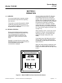
1-1 OVERVIEW
The Model 7003M Percent Oxygen Analyzer
continuously monitors the concentration of
oxygen in a gaseous sample. It consists of a
sensor and the analyzer. The sensor is
housed in a chamber assembly and is
connected to the analyzer by a shielded multi-
conductor cable.
The Model 7003M Percent Oxygen Analyzer
provides direct digital readout, isolated current
output, automatic temperature compensation
circuitry, and dual relay contact closures for
alarms or ON/OFF control devices as
standard features. The alarm ranges can be
selected independently from the output range,
eliminating the need to readjust alarm
setpoints if the range is changed.
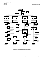
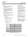
The analyzer has six modes of operation:
MODE FUNCTION
RUN (see Section 3-4 on page 3-10) Normal monitoring
SETUP (see Section 3-5 on page 3-11) Changing parameters
ALARM/CONTROL (see Section 3-6 on page 3-16) Set alarms or ON/OFF controllers
CALIBRATION (see Section 4-2 on page 4-1) Gas calibration/pressure inputs
HOLD (see Section 4-3 on page 4-5) Retain last output value
DIAGNOSTICS (see Section 4-4 on page 4-8) Electronics checks
The Model 7003M Percent Oxygen Analyzer
is housed in a NEMA 4X (CSA enclosure 4),
corrosion resistant housing suitable for panel,
pipe or wall mounting.
The analyzer has a microprocessor controlled
keyboard for operation. Signals from the
remote oxygen and temperature sensors are
processed to compute real time oxygen
concentration corrected for temperature,
constant pressure differences and residual
sensor current. The oxygen concentration is
compared with user-set alarm parameters,
and also generates an isolated 4 to 20 or 0 to
20mA signal. Data is stored in a memory
circuit that retains the data in case power is
removed.
The analyzer is shipped from the factory
configured for operation on either 115 VAC or
230 VAC, 50/60 Hz as specified by the
customer when ordered.
1-2 PRINCIPLE OF MEASUREMENT
Measurement is based on the electro-
chemical reaction between oxygen and the
sensor cathode which produces a low level
electrical current. The sensor signal is
proportional to the partial pressure of oxygen
present at the membrane. This signal and a
thermistor signal are received by the analyzer
and processed by the electronics to output a
calibrated oxygen signal that is compensated
for temperature.
1-3 SENSORS
Rosemount Analytical offers rechargeable and
disposable oxygen sensors which can be
used with the Model 7003M. These sensors
are supplied in kits: Submersion, in-line flow,
fast response, and a cell separation kit.
Sensors are available constructed of
polypropylene or Ryton. See Section 7-
4REPLACEMENT PARTS - SENSORS on
page 7-3, for additional information.

Operator Manual
748223-K
June 2002
1-2 Description and Specifications Rosemount Analytical Inc. A Division of Emerson Process Management
Model 7003M
1-4 CONDITIONS AFFECTING MEASUREMENT
Oxygen measurement is affected by the
following:
•
Composition of the sampled gas
•
Sample and calibration gas pressures
•
Environment of sensor, cable and
analyzer
Each must be considered when calibrating
and operating the analyzer to obtain accurate
measurements.
a. Gas Composition
Any substance in the sample that
significantly interferes or "poisons" the
sensor oxygen reading should be
removed by a chemical and/or
mechanical sample handling system (see
Section 5-2 on page 5-1). If ambient air is
not used as the span gas, the
composition of calibration gases should
also be representative of the sample.
The sample and calibration gases must
meet certain specifications (see
Specifications in Preface) to ensure
accurate measurement. Physical
parameters that affect measurement
include:
•
Pressure
•
Humidity
•
Temperature
•
Gas composition
Also refer to Section 5-2 on page 5-1 for
additional information about how gas
conditions affect the oxygen
measurement.
b. Sample and Cal Gas Pressures
The sample and calibration gases may be
at different pressures as long as the
pressure of each remains constant. Any
variation in the pressure of either gas will
result in an incorrect output reading of the
same proportion.
Two methods of sample calibration are
recommended:
1. Calibrate at the sample pressure, or
2. Calibrated at a different pressure, and
enter the two pressure in the analyzer
(Section 4-2c on page 4-4)
Refer to Section 5-2 on page 5-1 for a
more detailed discussion of the
relationship between gas pressures and
apparent oxygen concentration.
c. Environmental Factors
If radio frequency interference (RFI)
normally occurs in the operating
environment, the sensor cable should be
electrically shielded during installation.

Operator Manual
748223-K
June 2002
Rosemount Analytical Inc. A Division of Emerson Process Management Description and Specifications 1-3
Model 7003M
1-5 FEATURES
Suppressed Ranges
When setting the Model 7003M to a
suppressed output range (15 to 25%, etc.),
note that the absolute accuracy, drift, and
noise of the oxygen measurement will remain
the same for all ranges (see Specifications in
Preface).
ALARM Mode
ALARM Mode is not self-resetting. Operator
must press ACK to bring relays back to their
no-alarm state. Used when immediate
operator action is required.
NOTE:
Operator Can Bypass Alarm Relays
When relays are set to ALARM Mode (Sec-
tion 3-6a on page 3-16) and an alarm con-
dition has occurred, pressing the ACK key
will turn off the relay switch, whether the
oxygen level is out of range or not. If you
do not want an operator to be able to by-
pass the relay switches in this way, set the
instrument to ON/OFF -CONTROL Mode.
ON/OFF-Controller Mode
ON/OFF-CONTROLLER Mode is self-
resetting. Pressing ACK has no effect on
relay coils. Used when automated action is
required.

Operator Manual
748223-K
June 2002
1-4 Description and Specifications Rosemount Analytical Inc. A Division of Emerson Process Management
Model 7003M
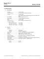
1-6 SPECIFICATIONS
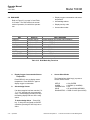
a. Performance
Accuracy........................................ ±0.25% oxygen
Operating Range ........................... 0 to 25% oxygen (endpoints set by user)
Linearity ......................................... ±0.25% oxygen
(with constant sample temperature after sensor zero offset correc-
tion)
Zero Stability.................................. ±0.25% oxygen/week at 25°C
Span Stability................................. ±0.25% oxygen/24 hours at 25°C
Noise ............................................. ±0.25% oxygen
Response Time ............................. 90% of reading in 20 seconds at 25°C
Temperature Effects
32 to 110°F (0 to 44°C) ......... ±6% reading
60 to 90°F (15 to 32°C) ......... ±3% reading
other 30°F (16°C) ranges ...... +4% reading
b. Physical
Mounting
Standard ................................ Panel Mount
Optional ................................. Wall Mount, Pipe Mount
Dimensions.................................... 5.7 x 5.7 x 7.6 inches (14 x 14 x 19 cm) HxWxD
Weight ........................................... Approximately 3.0 pounds (1.36 kg)
Enclosure....................................... ABS Plastic, Black, NEMA Type 4X, IP65
Ambient Humidity .......................... 95% relative humidity, non-condensing (maximum)
Ambient Temperature.................... 14 to 122°F (-10 to 50°C)
Sensor Cable................................. 2 twisted pairs, specified length up to 1000 feet (305 m) maximum
Power Cable.................................. 3 conductor, Type SJT, 18 AWG minimum
Connection Conduit
Power..................................... 1/2 inch
Sensor ................................... 3/4 inch

Operator Manual
748223-K
June 2002
Rosemount Analytical Inc. A Division of Emerson Process Management Description and Specifications 1-5
Model 7003M
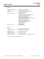
c. Electrical
Power Requirements..................... 115/230 VAC ±10%, 50/60 Hz ±3 Hz
Display........................................... 3-1/2 digit liquid crystal (LCD)
Signal Output................................. Isolated 4 to 20 or 0 to 20 mA (selectable)
600 ohms maximum load
Alarm Relay Contacts.................... Two Form C Relays
SPDT, resistive load, independently adjustable
Deadband adjustable over full range
Alarm Relay Contacts Ratings
General Purpose (Ordinary) Locations:
115 VAC, 3.0 A (resistive), 230 VAC, 1.5 A resistive
Class I, Division 2 Locations:
CSA: 120 VAC, 3.0 A (non-inductive)
240 VAC, 1.5 A (non-inductive).
FM: 28 VDC (resistive) (Ci = 0, Li = 0)
Groups A&B: 150 mA
Group C: 400 mA
Group D: 540 mA
Recorder Output............................ Isolated 4 to 20 mA
d. Sensors
Types............................................. Rechargeable and Disposable
Process Connections .................... Refer to flow chamber (if supplied)
Sample Pressure........................... 0 to 50 psig (0 to 345 kPa)
Sample Temperature..................... 32 to 110°F (0 to 44°C)
Ambient Temperature.................... 32 to 110°F (0 to 44°C)
Ambient Humidity .......................... 95% relative humidity, non-condensing (maximum)
Also refer to instructions supplied with sensor.

Operator Manual
748223-K
June 2002
1-6 Description and Specifications Rosemount Analytical Inc. A Division of Emerson Process Management
Model 7003M

Operator Manual
748223-K
June 2002
Rosemount Analytical Inc. A Division of Emerson Process Management Installation 2-1
Model 7003M
SECTION 2
INSTALLATION
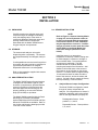
2-1 UNPACKING
Carefully examine the shipping carton and
contents for signs of damage. Immediately
notify the shipping carrier if the carton or
contents is damaged. Retain the carton and
packing material until all components
associated with the Model 7003M Percent
Oxygen Analyzer are operational.
2-2 STORAGE
The sensors and analyzer unit may be
shipped together or separately. The sensors
are shipped assembly and charged, ready for
use.
If rechargeable sensors are stored longer than
six months, they may need to be recharged or
rejuvenated if performance is marginal.
Disposable sensors are not rechargeable.
Refer to documentation supplied with sensors
for more information.
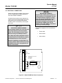
2-3 ANALYZER INSTALLATION
The Model 7003M Percent Oxygen Analyzer
is designed to meet NEMA Type 4X (CSA
enclosure 4) requirements, provided that the
cutouts in the bottom of the enclosure are
fitted with approved conduit fittings or are
properly sealed by the user with Hoffman
plugs (PN A-S050) or equivalent.
The Model 7003M is supplied with the Panel
Mounting Kit PN 652527 as standard.
Optional Wall Mount Kit PN 652539 and Pipe
Mount Kit PN 652529 are available. Refer to
the Outline and Mounting drawings provided
in the rear of this manual.
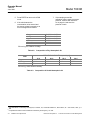
2-4 SENSOR INSTALLATION
NOTE:
Refer to Figure 2-1 Sensor Ordering Matrix
on page 2-2, and verify that the sensor to
be used corresponds with the application.
If an incorrect sensor is used, calibration
may be impossible or incorrect. If a differ-
ent type of sensor is to be used, the rocker
switch (SW1) on the Signal Board may
have to be changed (see Section 2-4a
below).
Install the sensor in an area where
temperature is relatively constant, taking care
to avoid changes in exposure to sunlight or
due to sudden drafts. A room-temperature
environment is preferable. The flow
chamber/sensor kit contains detailed
mounting and sample flow information. Add
distilled or deionized water to the sensor to
the maximum level indication on the sensor
reservoir. Let sensor stand for approximately
15 minutes and check for leaks around the
base of the reservoir, and at the seams and
corners. If a leak is found, contact the factory
before proceeding. Drain the sensor.
a. Analyzer/Sensor Jumper Configuration
The Model 7003M is configured to match
the type of sensor ordered with the
analyzer. If the Signal Board or Sensor is
repaired or replaced, verify rocker switch
SW1 on the Signal Board is properly set.
Rechargeable Sensor: Close
positions 1, 4, and 5
Disposable Sensor: Close positions
2, 4, and 6

Operator Manual
748223-K
June 2002
2-2 Installation Rosemount Analytical Inc. A Division of Emerson Process Management
Model 7003M
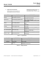
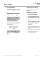
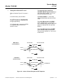
Figure 2-1. Sensor Ordering Matrix
4 0 0 0 3
6
4000 Rechargeable Sensor
5000 Disposable Sensor
1 Polypropylene
2 Ryton (rechargeable only)
9 Special (consult factory)
1 Submersion
2 In-Line Flow
3 Fast Response (rechargeable only)
9 Special (consult factory)
Position →
Positions 1 through 4 = Sensor Type
Position 5 = Material of Construction (Sensor and Flow Assembly)
Position 6 = Flow Assembly Configuration
Example 400013 is a Rechargeable sensor, constructed of polypropylene, mounted in a
Fast-Response Flow Chamber Assembly.
1234
5
1
Page is loading ...
Page is loading ...
Page is loading ...
Page is loading ...
Page is loading ...
Page is loading ...
Page is loading ...
Page is loading ...
Page is loading ...
Page is loading ...
Page is loading ...
Page is loading ...
Page is loading ...
Page is loading ...
Page is loading ...
Page is loading ...
Page is loading ...
Page is loading ...
Page is loading ...
Page is loading ...
Page is loading ...
Page is loading ...
Page is loading ...
Page is loading ...
Page is loading ...
Page is loading ...
Page is loading ...
Page is loading ...
Page is loading ...
Page is loading ...
Page is loading ...
Page is loading ...
Page is loading ...
Page is loading ...
Page is loading ...
Page is loading ...
Page is loading ...
Page is loading ...
Page is loading ...
Page is loading ...
Page is loading ...
Page is loading ...
Page is loading ...
Page is loading ...
Page is loading ...
Page is loading ...
Page is loading ...
Page is loading ...
Page is loading ...
Page is loading ...
Page is loading ...
Page is loading ...
Page is loading ...
Page is loading ...
-
 1
1
-
 2
2
-
 3
3
-
 4
4
-
 5
5
-
 6
6
-
 7
7
-
 8
8
-
 9
9
-
 10
10
-
 11
11
-
 12
12
-
 13
13
-
 14
14
-
 15
15
-
 16
16
-
 17
17
-
 18
18
-
 19
19
-
 20
20
-
 21
21
-
 22
22
-
 23
23
-
 24
24
-
 25
25
-
 26
26
-
 27
27
-
 28
28
-
 29
29
-
 30
30
-
 31
31
-
 32
32
-
 33
33
-
 34
34
-
 35
35
-
 36
36
-
 37
37
-
 38
38
-
 39
39
-
 40
40
-
 41
41
-
 42
42
-
 43
43
-
 44
44
-
 45
45
-
 46
46
-
 47
47
-
 48
48
-
 49
49
-
 50
50
-
 51
51
-
 52
52
-
 53
53
-
 54
54
-
 55
55
-
 56
56
-
 57
57
-
 58
58
-
 59
59
-
 60
60
-
 61
61
-
 62
62
-
 63
63
-
 64
64
-
 65
65
-
 66
66
-
 67
67
-
 68
68
-
 69
69
-
 70
70
-
 71
71
-
 72
72
-
 73
73
-
 74
74


Emerson 7003M User manual
- Category
- Oxygen Equipment
- Type
- User manual
- This manual is also suitable for
Ask a question and I''ll find the answer in the document
Finding information in a document is now easier with AI
Related papers
-
Rosemount 755A User manual
-
-
-
-
Rosemount MicroCEM-Rev A User manual
-
-
-
-
-
Other documents
-
-
-
-
Emerson Process Management 755R O2 Analyzer-Rev S User manual
-
-
-
-
-
-