ASROCK P4I65GV User manual

Category
Motherboards
Type
User manual
1
P4i65GV
User Manual
Version 1.1
Published April 2004
Copyright©2004 ASRock INC. All rights reserved.
2
Copyright Notice:
No part of this manual may be reproduced, transcribed, transmitted, or translated in
any language, in any form or by any means, except duplication of documentation by
the purchaser for backup purpose, without written consent of ASRock Inc.
Products and corporate names appearing in this manual may or may not be regis-
tered trademarks or copyrights of their respective companies, and are used only for
identification or explanation and to the owners’ benefit, without intent to infringe.
Disclaimer:
Specifications and information contained in this manual are furnished for informa-
tional use only and subject to change without notice, and should not be constructed
as a commitment by ASRock. ASRock assumes no responsibility for any errors or
omissions that may appear in this manual.
With respect to the contents of this manual, ASRock does not provide warranty of
any kind, either expressed or implied, including but not limited to the implied warran-
ties or conditions of merchantability or fitness for a particular purpose.
In no event shall ASRock, its directors, officers, employees, or agents be liable for
any indirect, special, incidental, or consequential damages (including damages for
loss of profits, loss of business, loss of data, interruption of business and the like),
even if ASRock has been advised of the possibility of such damages arising from any
defect or error in the manual or product.
This device complies with Part 15 of the FCC Rules. Operation is subject to the
following two conditions:
(1) this device may not cause harmful interference, and
(2) this device must accept any interference received, including interference that
may cause undesired operation.
ASRock Website: http://www.asrock.com
3
Contents
1 Introduction ................................................... 5
1.1 Package Contents.......................................................... 5
1.2 Specifications................................................................ 6
1.3 Supported AGP VGA Cards Lists ................................. 8
1.4 Motherboard Layout ...................................................... 10
1.5 ASRock I/O Plus
TM
.......................................................... 11
2 Installation...................................................... 12
Pre-installation Precautions ................................................... 12
2.1 CPU Installation .............................................................. 13
2.2 Installation of CPU Fan and Heatsink ............................ 13
2.3 Installation of Memory Modules (DIMM)......................... 14
2.4 Expansion Slots (PCI, AMR, and AGI Slots) .................. 15
2.5 Easy Dual Monitor Feature............................................. 16
2.6 Jumpers Setup .............................................................. 16
2.7 Onboard Headers and Connectors .............................. 17
2.8 Serial ATA (SATA) Hard Disks Installation ..................... 20
3 BIOS SETUP UTILITY........................................... 21
3.1 Introduction .................................................................... 21
3.1.1 BIOS Menu Bar .................................................... 21
3.1.2 Navigation Keys ................................................... 22
3.2 Main Screen................................................................... 22
3.3 Advanced Screen ......................................................... 23
3.3.1 CPU Configuration................................................ 23
3.3.2 Chipset Configuration .......................................... 24
3.3.3 ACPI Configuration ............................................... 26
3.3.4 IDE Configuration ................................................. 27
3.3.5 PCIPnP Configuration ........................................... 29
3.3.6 Floppy Configuration ........................................... 30
3.3.7 Super IO Configuration ........................................ 30
3.3.8 USB Configuration ............................................... 32
3.4 Hardware Health Event Monitoring Screen .................. 32
3.5 Boot Screen................................................................... 33
3.5.1 Boot Settings Configuration.................................. 33
3.5.2 Boot Device Priority............................................... 34
3.6 Security Screen ............................................................ 34
3.7 Exit Screen .................................................................... 35
4
4 Software Support ........................................... 36
4.1 Install Operating System ............................................... 36
4.2 Support CD Information ................................................. 36
4.2.1 Running Support CD ............................................ 36
4.2.2 Drivers Menu........................................................ 36
4.2.3 Utilities Menu ........................................................ 36
4.2.4 ASRock “PC-DIY Live Demo” Program ................. 36
4.2.5 Contact Information.............................................. 36
5
Chapter 1 Introduction
Thank you for purchasing ASRock P4i65GV motherboard, a reliable motherboard
produced under ASRock’s consistently stringent quality control. It delivers excellent
performance with robust design conforming to ASRock’s commitment to quality and
endurance.
In this manual, chapter 1 and 2 contain introduction of the motherboard and step-by-
step guide to the hardware installation. Chapter 3 and 4 contain the configuration
guide to BIOS setup and information of the Support CD.
Because the motherboard specifications and the BIOS software might be
updated, the content of this manual will be subject to change without
notice. In case any modifications of this manual occur, the updated
version will be available on ASRock website without further notice. You
may find the latest memory and CPU support lists on ASRock website as
well. ASRock website
http://www.asrock.com
1.1 Package Contents
ASRock P4i65GV Motherboard
(Micro ATX Form Factor: 9.6-in x 7.8-in, 24.4 cm x 19.8 cm)
ASRock P4i65GV Quick Installation Guide
ASRock P4i65GV Support CD
One 80-conductor Ultra ATA 66/100 IDE Ribbon Cable
One Ribbon Cable for a 3.5-in Floppy Drive
One Serial ATA (SATA) Data Cable
One Serial ATA (SATA) HDD Power Cable (Optional)
One ASRock I/O Plus
TM
Shield
One COM Port Bracket
One ASRock MR Card (Optional)
6
1.2 Specifications
Platform: Micro ATX Form Factor: 9.6-in x 7.8-in, 24.4 cm x 19.8 cm
CPU: Socket 478, supports Intel
®
Pentium
®
4
(Prescott, Northwood,
Willimate) / Celeron
®
processor
Chipsets: North Bridge:
Intel
®
865GV chipset, FSB @ 800 / 533 / 400MHz,
supports Hyper-Threading Technology (see CAUTION 1)
South Bridge:
Intel
®
ICH5, supports SATA 1.5Gb/s
Memory: 2 DDR DIMM slots: DDR1 and DDR2
supports PC3200 (DDR400) / PC2700 (DDR333) /
PC2100 (DDR266), Max. 2GB (see CAUTION 2)
Dual Channel Memory Technology support(see CAUTION 3)
IDE: IDE1: ATA 100 / Ultra DMA Mode 5
IDE2: ATA 100 / Ultra DMA Mode 5
Supports up to 4 IDE devices
Serial ATA: Supports up to 2 SATA devices at 1.5Gb/s data transfer rate.
(No Support for “RAID” and “Hot Plug” functions)
Floppy Port: Supports up to 2 floppy disk drives
Audio: 5.1 channels AC’97 Audio
PCI LAN: Speed: 802.3u (10/100 Ethernet), supports Wake-On-LAN
Hardware Monitor:CPU temperature sensing,
Chassis temperature sensing,
CPU overheat shutdown to protect CPU life
(ASRock U-COP)(see CAUTION 4),
CPU fan tachometer,
Chassis fan tachometer,
Voltage monitoring: +12V, +5V, +3V, Vcore
PCI slots: 3 PCI slots with PCI Specification 2.2 (see CAUTION 5)
AMR slot: 1 slot, supports ASRock MR card (Optional)
AGI slot: 1 AGI [ASRock Graphics Interface] slot (see CAUTION 6)
USB 2.0: 8 USB 2.0 ports:
includes 6 default USB 2.0 ports on the rear panel,
plus one header to support 2 additional USB 2.0 ports
(see CAUTION 7)
ASRock I/O Plus
TM
: 1 PS/2 mouse port, 1 PS/2 keyboard port,
1 VGA port, 1 parallel port: ECP/EPP support,
6 default USB 2.0 ports,
1 RJ 45 port,
Audio Jack: Line In / Line Out / Microphone
COM Port: 1 COM Port Header to support a COM port module
7
BIOS: AMI legal BIOS, Supports “Plug and Play”,
ACPI 1.1 compliance wake up events,
Supports jumperfree, SMBIOS 2.3.1 support,
CPU frequency stepless control
(only for advanced users’ reference, see CAUTION 8)
OS: Microsoft
®
Windows
®
98 SE / ME / 2000 / XP compliant
CAUTION!
1. About the setting of “Hyper Threading Technology”, please check page 24.
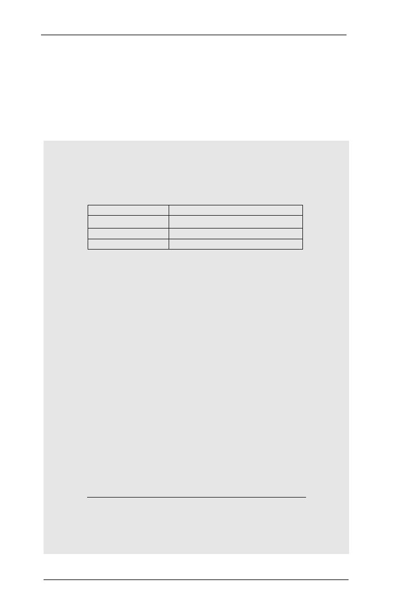
2. Please check the table below for the memory support frequency and its
corresponding CPU FSB frequency.
CPU FSB Frequency Memory Support Frequency
800 DDR266, DDR320
*, DDR400
533 DDR266, DDR333
400 DDR266
* When you use an FSB800-CPU on this motherboard, it will run at
DDR320 if you adopt a DDR333 memory module.
3. This motherboard supports Dual Channel Memory Technology. Before you
implement Dual Channel Memory Technology, make sure to read the
installation guide of memory modules on page 14 for proper installation.
4. While CPU overheat is detected, the system will automatically shutdown.
Before you resume the system, please check if the CPU fan on the
motherboard functions properly and unplug the power cord, then plug it
back again. To improve heat dissipation, remember to spray thermal
grease between the CPU and the heatsink when you install the PC system.
5. Because the installed AMR card will occupy the same external connecting
position with the PCI card that are installed in “PCI3” slot, you will not be
able to install any PCI card in “PCI3” slot if an AMR card has already been
installed in the AMR slot.
6. The AGI [ASRock Graphics Interface] slot is a special design that only
supports compatible AGP VGA cards. For the information of the
compatible AGP VGA cards, please refer to the “Supported AGP VGA
Cards List” on page 8 and page 9. For the proper installation of AGP
VGA card, please refer to the installation guide on page 15.
7. Power Management for USB 2.0 works fine under Microsoft
®
Windows
®
XP
SP1 / 2000 SP4. It may not work properly under Microsoft
®
Windows
®
98/
ME. Please refer to Microsoft
®
official document at
http://www.microsoft.com/whdc/hwdev/bus/USB/USB2support.mspx
8. Although this motherboard offers stepless control, it is not recommended
to perform over-clocking. Frequencies other than the recommended CPU
bus frequencies may cause the instability of the system or damage the
CPU.
8
1.3 Supported AGP VGA Cards List
(for Windows 2000/Windows XP)
I. AGP 4X
Graphics Chip Model Name
Vendor
n-VIDIA ASUS AGP-V7100
ASUS AGP-V7100PRO
ASUS AGP-V7100 MAGIC / 32M
ASUS AGP-V7700Ti
ASUS AGP-V8170DDR
ASUS AGP-V8170SE / LP
ASUS AGP-V8200 T2
ASUS AGP-V8200 T5
ASUS AGP-V8440
ASUS AGP-V8460 Ultra
GAINWARD- GF3-TI500/64M
GAINWARD- GF3-TI500/128M
Inno3D GeForce2 MX400
Leadtek WinFast A170 TH
Leadtek WinFast A170 DDR
Leadtek WinFast A250LE TD
Leadtek WinFast GeForce2 MX MX64
Leadtek WinFast GeForce2 H MX400
MSI- GF4-MX440SE
PROLINK GF4-MX440
SPARKLE GF4-MX440
ATI Gigabyte GV-AP64D
Gigabyte GV-AP64D-H
Gigabyte GV-AR64S-H
POWERCOLOR RADEON 9000
POWERCOLOR RADEON 9100
TRANSCEND TS64MVDR7
SiS SYNNEX GCM-SiS315EA32
For the latest updates of the supported AGP VGA cards list, please visit
ASRock website for details.
ASRock website: http://www.asrock.com/support/index.htm
9
II. AGP 8X
Graphics Chip Model Name
Vendor
n-VIDIA ALBATRON GF4-MX440 64M
AOPEN Aeolus FX5600S-DV128
AOPEN Aeolus FX5200-V128
ASUS AGP-V9180
ASUS AGP-V9280 VIEDO SUITE
ASUS AGP-V9520 MAGIC/T
ASUS V9900
ASUS V9900 ULTRA
ELSA-GLADIC 518
ELSA-GLADIC 518 P
Inno3D GeForce FX5600
LEADTEK A280 LE
LEADTEK A340TDH
MSI Ti4800SE-VTD8X
PALIT GF4 MX440 8X 64MB
PROLINK GeForceFX5900
PROLINK GF4-TI4200
SPARKLE GF4-MX440-8X
ATI CLUB3D ATI R9800
Gigabyte GV R9000 PRO
Gigabyte RADEON 9500
Gigabyte RADEON 9700 PRO
POWER COLOR 9200
SAPHIRE RADEON 9200-128MB
SiS POWER COLOR XABRE600
For the latest updates of the supported AGP VGA cards list, please visit
ASRock website for details.
ASRock website: http://www.asrock.com/support/index.htm
10
1.4 Motherboard Layout
1 PS2_USB_PWR1 Jumper 17 System Panel Header (PANEL1)
2 CPU Heatsink Retention Module 18 Chassis Speaker Header (SPEAKER 1)
3 CPU Socket 19 Infrared Module Header (IR1)
4 CPU Fan Connector (CPU_FAN1) 20 Floppy Connector (FLOPPY1)
5 North Bridge Controller 21 AMR Slot (AMR1)
6 184-pin DDR DIMM Slots (DDR1- 2, Dual Channel) 22 BIOS FWH Chip
7 ATX Power Connector (ATXPWR1) 23 COM Port Header (COM1)
8 Primary IDE Connector (IDE1, Blue) 24 PCI Slots (PCI1- 3)
9 Secondary IDE Connector (IDE2, Black) 25 JL1 Jumper
10 ASRock Graphics Interface Slot (AGP1) 26 JR1 Jumper
11 South Bridge Controller 27 Front Panel Audio Header (AUDIO1)
12 Clear CMOS Jumper (CLRCMOS0) 28 Internal Audio Connector: AUX1 (White)
13 Secondary Serial ATA Connector (SATA2) 29 Internal Audio Connector: CD1 (Black)
14 Primary Serial ATA Connector (SATA1) 30 Shared USB 2.0 Header (USB4_5, Blue)
15 USB 2.0 Header (USB67, Blue) 31 ATX 12V Connector (ATX12V1)
16 Chassis Fan Connector (CHA_FAN1)
FLOPPY1
20
AMR1
21
1
COM1
2MB
BIOS
22
Super
I/O
IR1
1
SPEAKER1
1
18
19
PANEL1
HDLED RESET
PLED PWRBTN
1
17
CHA_FAN1
16
CMOS
Battery
CLRCMOS0
AGP1
10
PCI 2
PCI 1
PCI 3
`
1
AUDIO1
JR1
JL1
AUDIO
CODEC
PCI
LAN
IDE1
8
IDE2
DDR1 (64/72 bit, 184-pin module)
DDR2 (64/72 bit, 184-pin module)
65
CPU_FAN1
4
PGA478
2
3
USB67
1
Intel
ICH5
ATXPWR1
SATA1
SATA2
1
USB4_5
AUX1
CD1
PS2_USB_PWR1
1
Intel
865GV
Chipset
ATX12V1
PARALLEL PORT
COM1
PS2
Mouse
PS2
Keyboard
USB 2.0
T: USB2
B: USB3
USB 2.0
T: USB0
B: USB1
Top:
RJ-45
Top:
Line In
Center:
Line Out
Bottom:
Mic In
USB 2.0
T: USB4
B: USB5
19.8cm (7.8 in)
1 7
24.4cm (9.6 in)
P4i65GV
9
DDR400
USB2.0SATA
5.1CH
11
12
13
14
15
23
24
26
25
27
28
29
30
31
11
1.5 ASRock I/O Plus
TM
1 Parallel Port 7 USB 2.0 Ports (USB01)
2 RJ-45 Port 8 USB 2.0 Ports (USB23)
3 Line In (Light Blue) 9 VGA Port
4 Line Out (Lime) 10 PS/2 Keyboard Port (Purple)
5 Microphone (Pink) 11 PS/2 Mouse Port (Green)
6 Shared USB 2.0 Ports (USB45)
1
2
3
4
5
6
7
8910
11
12
Chapter 2 Installation
P4i65GV is a Micro ATX form factor (9.6-in x 7.8-in, 24.4 cm x 19.8 cm) motherboard.
Before you install the motherboard, study the configuration of your chassis to en-
sure that the motherboard fits into it.
Pre-installation Precautions
Take note of the following precautions before you install motherboard com-
ponents or change any motherboard settings.
1. Unplug the power cord from the wall socket before touching any
component.
2. To avoid damaging the motherboard components due to static electricity,
NEVER place your motherboard directly on the carpet or the like. Also
remember to use a grounded wrist strap or touch a safety grounded
object before you handle components.
3. Hold components by the edges and do not touch the ICs.
4. Whenever you uninstall any component, place it on a grounded anti-
static pad or in the bag that comes with the component.
Before you install or remove any component, ensure that the power is
switched off or the power cord is detached from the power supply.
Failure to do so may cause severe damage to the motherboard,
peripherals, and/or components.
13
2.1 CPU Installation
Step 1. Unlock the socket by lifting the lever up to a 90° angle.
Step 2. Position the CPU directly above the socket such that its marked corner
matches the base of the socket lever.
Step 3. Carefully insert the CPU into the socket until it fits in place.
The CPU fits only in one correct orientation. DO NOT force the
CPU into the socket to avoid bending of the pins.
Step 4. When the CPU is in place, press it firmly on the socket while you push down
the socket lever to secure the CPU. The lever clicks on the side tab to
indicate that it is locked.
2.2 Installation of CPU Fan and Heatsink
This motherboard adopts 478-pin CPU socket to support Intel
®
Pentium
®
4
CPU. It requires larger heatsink and cooling fan to dissipate heat. You also
need to spray thermal grease between the CPU and the heatsink to
improve heat dissipation. Make sure that the CPU and the heatsink are
securely fastened and in good contact with each other. Then connect the
CPU fan to the CPU_FAN connector (CPU_FAN1, see page 10, No. 4). For
proper installation, please kindly refer to the instruction manuals of the
CPU fan and the heatsink.
STEP 1:
Lift The Socket Lever Up to 90°
STEP 2/STEP 3:
Match The CPU Marked Corner
to The Socket Marked Corner
STEP 4:
Push Down And Lock
The Socket Lever
Lift Lever Up to 90°
CPU Marked Corner
Socket Marked Corner
14
notch
break
notch
break
2.3 Installation of Memory Modules (DIMM)
P4i65GV motherboard provides two 184-pin DDR (Double Data Rate) DIMM slots,
and supports Dual Channel Memory Technology. For dual channel configuration,
you always need to install two identical (the same brand, speed, size and
chip-type) memory modules in the DDR DIMM slots to activate Dual Channel
Memory Technology. Otherwise, it will operate at single channel mode.
If you install only one memory module or two non-identical memory
modules, it is unable to activate the Dual Channel Memory Technology.
Installing a DIMM
Please make sure to disconnect power supply before adding or
removing DIMMs or the system components.
Step 1. Unlock a DIMM slot by pressing the retaining clips outward.
Step 2. Align a DIMM on the slot such that the notch on the DIMM matches the break
on the slot.
The DIMM only fits in one correct orientation. It will cause permanent
damage to the motherboard and the DIMM if you force the DIMM into the
slot at incorrect orientation.
Step 3. Firmly insert the DIMM into the slot until the retaining clips at both ends fully
snap back in place and the DIMM is properly seated.
15
2.4 Expansion Slots (PCI, AMR, and AGI Slots)
There are 3 PCI slots, 1 AMR slot, and 1 AGI slot on this motherboard.
PCI slots: PCI slots are used to install expansion cards that have the 32-bit PCI
interface.
Because the installed AMR card will occupy the same external
connecting position with the PCI card installed in “PCI3” slot, you
will no be able to install any PCI card in “PCI3” slot if an AMR card
has already been installed in the AMR slot.
AMR slot: AMR slot is used to insert an ASRock MR card (optional) with v.92
Modem functionality.
AGI slot: The AGI [ASRock Graphics Interface] slot is a special design that only
supports compatible AGP VGA cards. For the information of the compat-
ible AGP VGA cards, please refer to the “Supported AGP VGA Cards List”
on page 8 and page 9.
To install the system with an add-on AGP VGA card, you must make
sure to install the driver of add-on AGP VGA card before you install
the onboard VGA driver. If the onboard VGA driver has already been
installed before you install the add-on AGP VGA card, the system will
automatically set the onboard VGA as the primary graphics adapter. In
that case, if you want to install the add-on AGP VGA card, you need
to remove the onboard VGA driver first, and then install the add-on
AGP VGA card and its driver. For the detailed instruction, please refer
to the documents in the Support CD, “AGI Slot Installation Guide (for
Windows 2000)” and “AGI Slot Installation Guide (for Windows XP)”,
which are located in the folder at the following path:
..\ Easy Dual Monitor
Installing an expansion card
Step 1. Before installing the expansion card, please make sure that the power
supply is switched off or the power cord is unplugged. Please read the
documentation of the expansion card and make necessary hardware
settings for the card before you start the installation.
Step 2. Remove the system unit cover (if your motherboard is already installed in a
chassis).
Step 3. Remove the bracket facing the slot that you intend to use. Keep the screws
for later use.
Step 4. Align the card connector with the slot and press firmly until the card is
completely seated on the slot.
Step 5. Fasten the card to the chassis with screws.
Step 6. Replace the system cover.
16
2.5 Easy Dual Monitor Feature
Thanks to ASRock patented AGI8X Technology, this motherboard supports Easy
Dual Monitor upgrade. With the internal onboard VGA and the external add-on AGP
VGA card, you can easily enjoy the benefits of Dual Monitor feature. For the
detailed instruction, please refer to the document at the following path in the
Support CD: ..\ Easy Dual Monitor
2.6 Jumpers Setup
The illustration shows how jumpers are
setup. When the jumper cap is placed on
pins, the jumper is “Short”. If no jumper cap
is placed on pins, the jumper is “Open”. The
illustration shows a 3-pin jumper whose pin1
and pin2 are “Short” when jumper cap is
placed on these 2 pins.
Jumper Setting Description
PS2_USB_PWR1 Short pin2, pin3 to enable
(see p.10 No. 1) +5VSB (standby) for PS/2
or USB wake up events.
Note: To select +5VSB, it requires 2 Amp and higher standby current provided by
power supply.
JR1(see p.10 No. 26)
JL1(see p.10 No. 25)
Note: If the jumpers JL1 and JR1 are short, both the front panel and the rear panel
audio connectors can work.
Clear CMOS
(CLRCMOS0, 2-pin jumper)
(see p.10 No. 12)
Note: CLRCMOS0 allows you to clear the data in CMOS. The data in CMOS includes
system setup information such as system password, date, time, and system
setup parameters. To clear and reset the system parameters to default setup,
please turn off the computer andunplug the power cord, then use a jumper
cap to short the pins on CLRCMOS0 for 3 seconds. Please remember to
remove the jumper cap after clearing the CMOS. If you need to clear the CMOS
when you just finish updating the BIOS, you must boot up the system first, and
then shut it down before you do the clear-CMOS action.
+5V
1_2
+5VSB
2_3
2-pin jumper
JR1 JL1
17
FLOPPY1
Pin1
IDE1
PIN1
IDE2
PIN1
the red-striped side to Pin1
connect the black end
to the IDE devices
connect the blue end
to the motherboard
80-conductor ATA 66/100 cable
2.7 Onboard Headers and Connectors
Onboard headers and connectors are NOT jumpers. Do NOT place
jumper caps over these headers and connectors. Placing jumper caps
over the headers and connectors will cause permanent damage of the
motherboard!
FDD connector
(33-pin FLOPPY1)
(see p.10 No. 20)
Note: Make sure the red-striped side of the cable is plugged into Pin1 side of the
connector.
Primary IDE connector (Blue) Secondary IDE connector (Black)
(39-pin IDE1, see p.10 No. 8) (39-pin IDE2, see p.10 No. 9)
Note: If you use only one IDE device on this motherboard, please set the IDE
device as “Master”. Please refer to the instruction of your IDE device vendor
for the details. Besides, to optimize compatibility and performance, please
connect your hard disk drive to the primary IDE connector (IDE1, blue) and
CD-ROM to the secondary IDE connector (IDE2, black).
Serial ATA Connectors These two Serial ATA (SATA)
(SATA1: see p.10 No. 14) connectors support SATA data
(SATA2: see p.10 No. 13) cables for internal storage
devices. The current SATA
interface allows up to 1.5 Gb/s
data transfer rate.
Serial ATA (SATA) Either end of the SATA data cable
Data Cable can be connected to the SATA
hard disk or the SATA connector
on the motherboard.
SATA2
SATA1
18
GND
GND
+5VA
BACKOUT-R
BACKOUT-L
AUD-OUT-L
AUD-OUT-R
MIC-POWER
MIC
1
DUMMY
GND
+5V
IRTX
IRRX
1
USB_PWR
USB_PWR
P+6
P-6
P+7
P-7
GND
GND
DUMMY
1
USB_PWR
USB_PWR
P+5
P-5
P+4
P-4
GND
GND
DUMMY
1
Serial ATA (SATA) Please connect the black end of
Power Cable SATA power cable to the power
(Optional) connector on each drive. Then
connect the white end of SATA
power cable to the power
connector of the power supply.
USB 2.0 Header ASRock I/O Plus
TM
accommo-
(9-pin USB67) dates 6 default USB 2.0 ports. If
(see p.10 No. 15) those USB 2.0 ports on the I/O
panel are not sufficient, this
USB 2.0 header is available to
support 2 additional USB 2.0
ports.
Shared USB 2.0 Header This USB4_5 connector is shared
(9-pin USB4_5) with the USB 2.0 ports 4,5 on
(see p.10 No. 30) ASRock I/O Plus
TM
. When using
the front panel USB ports by
attaching the front panel USB
cable to this connector
(USB4_5), the USB ports 4,5 on
ASRock I/O Plus
TM
will not be able
to function.
Infrared Module Header This header supports an
(5-pin IR1) optional wireless transmitting
(see p.10 No. 19) and receiving infrared module.
Internal Audio Connectors These connectors allow you
(4-pin CD1, 4-pin AUX1) to receive stereo audio input
(CD1: see p.10 No. 29) from sound sources such as
(AUX1: see p.10 No. 28) a CD-ROM, DVD-ROM, TV
tuner card, or MPEG card.
Front Panel Audio Header This is an interface for front
(9-pin AUDIO1) panel audio cable that allows
(see p.10 No. 27) convenient connection and
control of audio devices.
CD-R
GND
GND
CD-L
AUX-R
GND
GND
AUX-L
CD1
AUX1
connect to the SATA HDD
power connector
connect to the
power supply
19
System Panel Header This header accommodates
(9-pin PANEL1) several system front panel
(see p.10 No. 17) functions.
Chassis Speaker Header Please connect the chassis
(4-pin SPEAKER 1) speaker to this header.
(see p.10 No. 18)
Chassis Fan Connector Please connect a chassis fan
(3-pin CHA_FAN1) cable to this connector and
(see p.10 No. 16) match the black wire to the
ground pin.
CPU Fan Connector Please connect a CPU fan cable
(3-pin CPU_FAN1) to this connector and match
(see p.10 No. 4) the black wire to the ground pin.
ATX Power Connector Please connect an ATX power
(20-pin ATXPWR1) supply to this connector.
(see p.10 No. 7)
COM Port Header This COM port header is used
(9-pin COM1) to support a COM port module.
(see p.10 No. 23)
ATX 12V Connector Please connect an ATX 12V
(4-pin ATX12V1) power supply to this connector.
(see p.10 No. 31)
GND
+12V
CHA_FAN_SPEED
+5V
DUMMY
DUMMY
SPEAKER
1
GND
PWRBTN#
PLED-
PLED+
DUMMY
RESET#
GND
HDLED+
HDLED-
1
GND
+12V
CPU_FAN_SPEED
CCTS#1
DDSR#1
DDTR#1
RRXD1
DDCD#1
TTXD1
GND
RRTS#1
RRI#1
1
20
2.8 Serial ATA (SATA) Hard Disks Installation
This motherboard adopts Intel ICH5 south bridge chipset that supports Serial ATA
(SATA) hard disks. You may install SATA hard disks on this motherboard for
internal storage devices. This section will guide you to install the SATA hard disks.
STEP 1: Install the SATA hard disks into the drive bays of your chassis.
STEP 2: Connect the SATA power cable to the SATA hard disk.
STEP 3: Connect one end of the SATA data cable to the motherboard’s SATA
connector.
STEP 4: Connect the other end of the SATA data cable to the SATA hard disk.
Before you install OS into the SATA hard disk, you need to check and
ensure the configuration of the OnBoard IDE Operate Mode option in
BIOS setup is correct according to the condition of your system. For
the configuration details, please refer to the instruction on page 27.
  • Page 1 1
  • Page 2 2
  • Page 3 3
  • Page 4 4
  • Page 5 5
  • Page 6 6
  • Page 7 7
  • Page 8 8
  • Page 9 9
  • Page 10 10
  • Page 11 11
  • Page 12 12
  • Page 13 13
  • Page 14 14
  • Page 15 15
  • Page 16 16
  • Page 17 17
  • Page 18 18
  • Page 19 19
  • Page 20 20
  • Page 21 21
  • Page 22 22
  • Page 23 23
  • Page 24 24
  • Page 25 25
  • Page 26 26
  • Page 27 27
  • Page 28 28
  • Page 29 29
  • Page 30 30
  • Page 31 31
  • Page 32 32
  • Page 33 33
  • Page 34 34
  • Page 35 35
  • Page 36 36

ASROCK P4I65GV User manual

Category
Motherboards
Type
User manual

Ask a question and I''ll find the answer in the document

Finding information in a document is now easier with AI