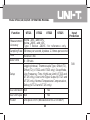
Uni-Trend UT321 Specification
- Category
- Environment thermometers
- Type
- Specification
This manual is also suitable for

Table of Contents
4
7
8
10
12
16
16
17
17
18
18
18
19
19
19
20
21
Title Page
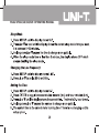
Safety Information
Getting Started
Components
Display Elements
Buttons
Using the Thermometer
Changing Setup Options
Entering and Exiting Setup
Changing the Logging Interval
Changing the Thermocouple Type
Changing the Offset (T1)
Changing the Offset (T2)
Sleep Mode
Changing the Line Frequency
Setting the Time
Setting the Low Limit Alarm (Lo)
Setting the High Limit Alarm (Hi)
1
Model UT321/322/323/325: OPERATING MANUAL

23
23
24
25
25
26
26
26
26
27
27
27
28
29
29
30
31
31
Title Page
Measuring Temperatures
Connecting a Thermocouple
Displaying Temperatures
Holding the Displayed Temperatures
Turning on and off of display backlight
Viewing the MIN, MAX, and AVG Readings
Using the Offset to Adjust Probe Errors
Over Limit Alarm
Over Limit Signal Output
Debug
Using Memory
Starting and Stopping Logging
Viewing Logged Readings
Clearing Memory
Communicating with a PC
Enabling or Disabling Over Limit Signal Output
Enabling or Disabling Normal Temperature Compensation (NTC)
Enabling or Disabling Debug
Model UT321/322/323/325: OPERATING MANUAL
2

Maintenance
Replacing the Battery
Cleaning the Case
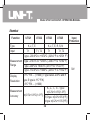
Specifications
Environmental
General
Electrical
Title Page
32
32
32
33
33
33
33
Model UT321/322/323/325: OPERATING MANUAL
3

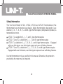
Safety Information
The Uni-Trend Model UT321, UT322, UT323 and UT325 Thermometers (‘the
thermometer) are microprocessor-based, digital thermometers designed to use
external J-, K-, T-, E-, R-, S- and N- type thermocouples (temperature probes) as
temperature sensors.
UT321: T1, suitable for K-, J-, T- and E- type thermocouples
UT322: T1 and T2, suitable for K-, J-, T- and E- type thermocouples
UT323: T1, suitable for K-, J-, T-, E-, R-, S- and N- type thermocouples. Equipped
with over limit alarm, over limit signal output and user self-debug features.
UT325: T1 and T2, suitable for K-, J-, T-, E-, R-, S- and N- type thermocouples.
Equipped with over limit alarm, over limit signal output and user self-debug features.
Use the thermometer only as specified in this manual. Otherwise, the protection
provided by the meter may be impaired.
Model UT321/322/323/325: OPERATING MANUAL
4

Refer to safety information in Table 1 and the international symbols in Table 2.
Table 1. Safety Information
Before using the thermometer inspect the case. Do not use the thermometer if it
appears damaged. Look for cracks or missing plastic. Pay particular attention to the
insulation around the connectors.
Disconnect the thermocouple(s) from the thermometer before opening the case.
Replace the batteries as soon as the battery indicator ( ) appears. The possibility
of false readings can lead to personal injury.
Do not use the thermometer if it operates abnormally. Protection may be impaired.
When in doubt, have the thermometer serviced.
Do not operate the thermometer around explosive gas, vapor, or dust.
Do not apply more than the rated voltage, as marked on the thermometer (30V|),
between the thermocouple(s), or between any thermocouple and earth ground.
When potential differences are anticipated between the thermocouples, use electrically
insulated thermocouples.
When servicing the thermometer, use only specified replacement parts.
Do not use the thermometer with any part of the case or cover removed.
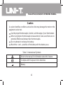
Warning
A warning identified conditions and actions that pose hazards to the user. To avoid
electrical shock or personal injury, follow these guidelines:
Model UT321/322/323/325: OPERATING MANUAL
5

Caution
A caution identifies conditions and actions that may damage the meter or the
equipment under test.
Use the proper thermocouples, function, and the range of your thermometer.
When carrying two thermocouples measurement, make sure there are no
potential differences between two thermocouples.
Do not attempt to recharge the battery.
Match the + and – polarities of the battery with the battery case.
Table 2. International Symbols
Refer to the manual for information about this feature
Complies with European Union directives
Battery
Model UT321/322/323/325: OPERATING MANUAL
6

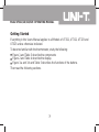
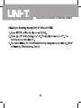
Getting Started
Everything in this Users Manual applies to all Models of UT321, UT322, UT323 and
UT325 unless otherwise indicated.
To become familiar with the thermometer, study the following:
Figure 1 and Table 3 describe the components
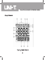
Figure 2 and Table 4 describe the display.
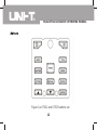
Figure 3-a and 3-b and Table 5 describes the functions of the buttons.
Then read the following sections.
Model UT321/322/323/325: OPERATING MANUAL
7

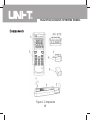
Figure 1. Components
Model UT321/322/323/325: OPERATING MANUAL
8

Table 3. Components
Display
Buttons
Thermocouple T1 input
Thermocouple T2 input (UT323 and UT325 only)
USB Port
SIGN Port - Over Limit Signal Output (UT323 and UT325 only)
NTC
Battery Door
9V battery (6F22 )
1
2
3
4
5
6
7
8
9
Model UT321/322/323/325: OPERATING MANUAL
9

Model UT321/322/323/325: OPERATING MANUAL
10

Table 4. Display Elements
Setup is in progress when the icon blinks
Display readings of maximum, minimum and average
Data Transferring is in progress
Logged readings are displayed when the icon blinks
Low battery. Replace the battery
The thermocouple type
The temperature units
Secondary Display 1
Under Calibration mode when the icon blinks. The displayed reading is fixed.
Secondary Display 2
The thermocouple measurement includes an offset. See “Changing Setup
Options”
Readings are being logged when the icon blinks
Primary Display
The displayed readings do not change
The symbol of display backlight
1
2
3
4
5
6
7
8
9
10
11
12
13
14
Model UT321/322/323/325: OPERATING MANUAL
11

Figure 3-a UT321 and UT323 buttons set
Model UT321/322/323/325: OPERATING MANUAL
12

Figure 3-b UT322 and UT325 button set
Model UT321/322/323/325: OPERATING MANUAL
13

Table 5. Buttons
Press to turn the thermometer on or off
Press to turn the display backlight on and off.
Press to freeze or unfreeze the displayed readings
Press to switch between Celsius (ºC), Fahrenheit(ºF), and Kelvin (K)
Press to step through the maximum, minimum, and average readings.
Press and hold to turn off this display.
Press to step through K-, J-, T-, E- (R-, S-, N-) type thermocouple.
Press to toggle showing the T1, T2 and T1-T2 (differential temperature
measurement) in the primary or secondary display 1
Press to enter USB mode and the USB icon blinks. Press again to exit
USB mode.
Press to start or stop logging.
(See “Using Memory - Starting and Stopping Logging”.)
Press to show logged readings
Press again to stop.
MAX MIN
HOLD
ºC ºF
SEND
STORE
RECALL
Model UT321/322/323/325: OPERATING MANUAL
14

Press to start or exit Setup.
Press to scroll the Setup option you want to change
(See “Changing Setup Options”)
After entering the Setup mode, press to increase the displayed setting.
(See “Changing Setup Options”)
After entering the Setup mode, press to decrease the displayed setting.
(See “Changing Setup Options”)
Confirm button.
(See “Changing Setup Options”)
Table 5. Buttons
ENTER
SETUP
Model UT321/322/323/325: OPERATING MANUAL
15

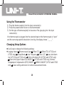
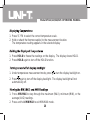
Using the Thermometer
1) Plug the thermocouple(s) into the input connector(s).
2) Press the power button to turn on the thermometer.
3) Set the type of thermocouple(s) to be same of the type plug into the input
connector(s).
If no thermocouple is plugged into the selected input or the thermocouple is “open”
and the over-range positive deviation is too big, the display shows “_ _ _ _“.
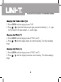
Changing Setup Options
Use Setup to change the following settings:
Logging interval Thermocouple type Offset (T1) Offset (T2) (UT322 and
UT325 only) Sleep Mode Line Frequency Time (S-T) Low Limit Alarm
(Lo) (UT323 and UT325 only) High Limit Alarm (Hi) (UT323 and UT325 only)
Over Limit Signal Output (SI) ON/OFF (UT323 and UT325 only) Normal
Temperature Compensation (NTC) ON/OFF DEBUG ON/OFF (UT323 and UT325
only) Save setting and return to normal measurement mode.
Model UT321/322/323/325: OPERATING MANUAL
16

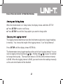
When the thermometer is in Setup mode, the display shows and blinks SETUP.
Press SETUP to start or exit Setup.
Press SETUP to scroll the Setup option you want to change after
The logging interval determines how often the thermocouple stores logged readings
in memory. You choose the length of the logging interval. See “Using Memory”.
Press SETUP until the display shows INTERVAL.
The thermometer stores logged readings at the end of each logging interval. You can
select a logging interval by pressing or . Holding down or causes the number
to change more quickly. The maximum interval is 59:59 and the minimum interval
is 00:00. When the logging interval is 00.00, you need to store the readings manually
as the auto store feature will be disabled.
Model UT321/322/323/325: OPERATING MANUAL
17

1. Press SETUP until the display shows TYPE.
2. Press or to select the thermocouple type you want including K-, J-, E- type
(UT323 and UT325 have extra R-, S- and N- type).
1. Press SETUP until the display shows OFFSET and T1
2. Press or until the display shows the correct reading. The offset readings
range
1. Press SETUP until the display shows OFFSET and T2
2. Press or until the display shows the correct reading. The offset readings
range
Model UT321/322/323/325: OPERATING MANUAL
18

Model UT321/322/323/325: OPERATING MANUAL
19

Model UT321/322/323/325: OPERATING MANUAL
20
Page is loading ...
Page is loading ...
Page is loading ...
Page is loading ...
Page is loading ...
Page is loading ...
Page is loading ...
Page is loading ...
Page is loading ...
Page is loading ...
Page is loading ...
Page is loading ...
Page is loading ...
Page is loading ...
Page is loading ...
Page is loading ...
Page is loading ...
-
 1
1
-
 2
2
-
 3
3
-
 4
4
-
 5
5
-
 6
6
-
 7
7
-
 8
8
-
 9
9
-
 10
10
-
 11
11
-
 12
12
-
 13
13
-
 14
14
-
 15
15
-
 16
16
-
 17
17
-
 18
18
-
 19
19
-
 20
20
-
 21
21
-
 22
22
-
 23
23
-
 24
24
-
 25
25
-
 26
26
-
 27
27
-
 28
28
-
 29
29
-
 30
30
-
 31
31
-
 32
32
-
 33
33
-
 34
34
-
 35
35
-
 36
36
-
 37
37


Uni-Trend UT321 Specification
- Category
- Environment thermometers
- Type
- Specification
- This manual is also suitable for
Ask a question and I''ll find the answer in the document
Finding information in a document is now easier with AI
Related papers


Other documents
-
Fluke 53 II Temperature Logging Digital Thermometer User manual
-
Digi-Sense WD-20250-03 Owner's manual
-
-
-
Mastech MS6512 User manual
-
-
 PerfectPrime tc2100 User manual
-
-
 UEi DT304 User manual
-
UEi Test Instruments FINE341 Owner's manual

