Craftsman 486.24212 Owner's manual
- Category
- Garden tools
- Type
- Owner's manual
This manual is also suitable for

Owner's Manual
I CRRFTSHAN I
46" LAWNSWEEPER
FOR SWEEPER/DETHATCHER COMBO
Model No. 486.24212
CAUTION:
Before using this product, read
this manual and follow all Safety
Rules and
Operating Instructions.
IMPORTANT - READ THIS FIRST!!!
For Missing Parts or Assembly Questions
Please Call 217-728-8388
Mon.-Fri. 7 am - 5 pm CST.
Missing parts will be sent UPS in 24 hours directly to your home.
• Safety
• Assembly
• Operation
• Maintenance
• Parts
Sears, Roebuck and Co., Hoffman Estates, IL 60179 U.S.A.
www.sears.com/craftsman
PRINTED IN U.S.A. FORM NO. 48825 (1/03)

Safety Rules ...................................................................... 2
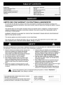
Full Size Hardware Chart.................................................. 3
Carton Contents ................................................................ 4
Sweeper Assembly Instructions ........................................ 5
Hopper Assembly Instructions .......................................... 7
Operation ........................................................................ 11
Maintenance Schedule ................................................... 12
Storage ........................................................................... 12
Service and Adjustments ................................................ 13
Troubleshooting .............................................................. 13
Repair Parts Illustration .................................................... 14
Repair Parts List.............................................................. 15
Parts Ordering/Service ..................................... Back Cover
LIMITED ONE YEAR WARRANTY ON CRAFTSMAN LAWNSWEEPER
For one year from the date of purchase, when this Lawnsweeper is maintained and lubricated according to the
operating and maintenance instructions in the owner's manual, Sears will repair free of charge any defect in material
or workmanship.
This warranty does not cover repairs necessary because of operator abuse or negligence, including the failure to
maintain the equipment according to instructions contained in the owner's manual; and Lawnsweeper used for
commercial or rental purposes.
WARRANTY SERVICE IS AVAILABLE BY CONTACTING THE NEAREST SEARS SERVICE CENTER/DEPART-
MENT IN THE UNITED STATES.
This warranty applies only while this product is in the United States.
This warranty gives you specific legal rights, and you may also have other rights which vary from state to state.
Sears, Roebuck and Co. D/817WA, Hoffman Estates, Chicago, IL 60179
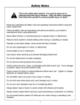
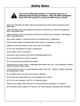
Any power equipment can cause injury if operated improperly or if the user does not understand how to operate
the equipment. Exercise caution at all times, when using power equipment.
• Read the vehicle and sweeper owners manuals and
know how to operate your vehicle and sweeper
before using this sweeper attachment. Always
instruct other users before they operate the sweeper.
• Do not permit children to operate sweeper.
• Do not permit anyone to ride on sweeper.
• Never attach the hopper rope to any part of your
body or clothing! Never hold onto the rope while
towing the sweeper! Attach the rope to the towing
vehicle to keep it away from wheels and rotating
parts.
• Operate the sweeper at reduced speed on rough
terrain, near ditches and on hillsides to prevent loss
of control.
• Vehicle braking and stability may be affected with the
attachment of this sweeper. Do not fill sweeper to
maximum capacity without checking the capability of
the towing vehicle to safely pull and stop with the
sweeper attached. Stay off of steep slopes.
• Stop and inspect vehicle and sweeper for damage
after striking an object. Repair any damage before
continuing operation.
• Keep sweeper away from fire. Excessive heat can
damage the brushes and hopper bag and could
cause the bag and its contents to burn.
• Before storing the sweeper, always empty the hopper
bag to avoid spontaneous combustion.
• Follow maintenance and lubrication instructions as
outlined in the maintenance section of this manual.
,_ Look for this symbol to point out important safety precautions. It means--Attention!!
Become alert!! Your safety is involved.
The model and serial numbers wilt be found on a decal
attached to the lawnsweeper.
You should record both the serial number and the date of
purchase and keep in a safe place for future reference.
MODEL NUMBER:
SERIAL NUMBER:
DATE OF PURCHASE:
486.24212
2

A
J
J
f
/
/
J
J
J
J
J
J
/B
SHOWN FULL SIZE
W
x
J
ol
JR
_Q
Y
J
J
NOT SHOWN FULL SIZE
CC /--EE __FF _-_
_DD
JGG
REF. QTY.
A
B
C
D
E
F
G
H
I
J
K
L
M
N
O
P
Q
2
1
1
4
2
1
5
2
1
6
4
4
2
6
1
2
2
DESCRIPTION REF. QTY.
Hex Bolt, 5/16-18 x 3" Lg.
Hex Bolt, 5/16-18 x 2-1/2" Lg.
Hex Bolt, 5/16-18 x 2-1/4" Lg.
Carriage Bolt, 5/16-18 x 1-3/4" Lg.
Curved Hd. Bolt, 5/16" x 1-5/8"
Carriage Bolt, 3/8-16 x 1" Lg.
Carriage Bolt, 5/16-18 x 3/4" Lg.
R
S
T
U
V
W
X
DESCRIPTION
2
1
1
1
6
2
2
Bowed Washer
Washer, Tooth Lock 5/16"
Cotter Pin, 1/8" x 3/4"
Hairpin Cotter, 1/8"
Hairpin Cotter, 3/32"
Clevis Pin, 3/8" x 1/2"
Clevis Pin, 1/4" x 1-1/8"
Hex Bolt, 5/16-18 x 3/4"
Hex Lock Nut, 3/8"
Hex Lock Nut, 5/16"
Hex Nut (Plain), 5/16"
Hex Nut (SEMS), 5/16"
Palnut, 3/8"
Lock Washer, 5/16"
Flat Washer, 1/2"
Flat Washer, 5/16" Standard
Flat Washer, 5/16" (Small)
Y
Z
AA
BB
CC
DD
EE
FF
GG
HH
II
2 Clevis Pin, 1/4" x 1-3/4"
1 Spacer Bushing,
2 Hitch Spacer, 3/4"
4 Hopper Mount Clamp
2 Vinyl Cap
3 Plastic Plug
1 Grip
1 Knob, Plastic
1 Hitch Pin
1 Spring
1 Angle Bracket
3

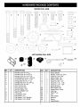
CARTON CONTENTS (Loose Parts in Carton)
1. Sweeper Housing Assembly
2. Bag Arm Tube (2)
3. Hitch Tube, L.H. (Left Hand)
4. Hitch Bracket
5. Hitch Bracket (Straight)
6. Hitch Pin Bracket
7. Height Adjustment Strap
8. Height Adjustment Handle
9. Hitch Tube, R.H. (Right Hand)
10. Rope
11. Hopper Bag
12. Upper Hopper Tube, R.H.
13. Upper Hopper Tube, L.H.
14. Rear Hopper Tube
15. Lower Hopper Side Tube (2)
16. Hopper Bag Pivot Rod
17. Hopper Support Rod (2)
18. Bag Frame Strap
15
15
11
\\
7
\4
5
CARTON CONTENTS
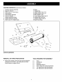
REMOVAL OF PARTS FROM CARTON
• Remove the sweeper, the loose parts and the hardware
package from the carton. Lay out the parts and hard-
ware as shown on pages 3 and 4.
TOOLS REQUIRED FOR ASSEMBLY
(1)
(1)
(1)
(1)
(1)
(1)
(1)
Pliers
Screwdriver
Hammer
Adjustable Wrench
9/16" Open End or Box End Wrench
1/2" Open End or Box End Wrench
3/8" Open End or Box End Wrench
4

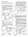
ASSEMBLY OF SWEEPER
Note: Right hand (R.H.) and left hand (L.H.) are deter-
mined from the operators position while seated on the
tractor.
• Assemble the angle bracket to the sweeper hous-
ing using a 5/16" x 3/4" hex bolt and a 5/16" hex
lock nut. Make sure the bracket is turned as shown
and aligned straight with the housing and then
tighten. See figure 1.
• Assemble the R.H. hitch tube to the sweeper
housing using two 5/16" x 1-3/4" carriage bolts,
5/16" lock washers and 5/16" hex nuts. Do not
tighten yet. Repeat for the L.H. hitch tube. See
figure 1.
5/16" HEX
LOCKNUT
5/16" HEX NUT
5/16"
WASHER _
5/16" x 1-3/4"
CARRIAGE BOLT
ANGLE
BRACKET
HEXBOLT
FIGURE 1
Assemble the transport hook (located in the
dethatcher carton) onto the L.H. hitch tube. See
figure 2.
Fasten the hitch tubes together using two 5/16" x
3" hex bolts, 5/16" small flat washers, 5/16" lock
washers and 5/16" hex lock nuts. Do not tighten
yet. See figure 2.
TRANSPORTHOOK
_rom d_h_cherca_on)
_16"HEX
LOCKNUT
_16"LOCK
_A----'_WASHER
_16"x3"
HEXBOLT
_16"SMALL
FLAT WASHER
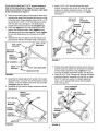
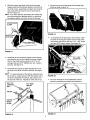
• Assemble the hitch pin bracket, the spring and the
1/2" flat washer onto the hitch pin. Secure them onto
the hitch pin with a 1/8" x 3/4" cotter pin placed into
the middle hole in the hitch pin. Spread ends of cotter
pin around hitch pin. See figure 3.
• Assemble the hitch pin bracket to the straight hitch
bracket using a 3/8" x 1" carriage bolt and a 3/8" hex
lock nut. Align the brackets and tighten. See figure 3.
3/8" x 1" CARRIAGE BOLT'_'_
1/8" x 3/4"
HITCH PIN
HITCH BRACKET
(STRAIGHT)
HITCH PIN
BRACKET
/"'---3/8"HEXLOCKNUT
MIDDLE HOLE
FIGURE 3
If your tractor hitch has 10" to 13" ground clearance
refer to the instructions for figure 4. If your tractor
hitch has less than 10" ground clearance, refer to the
instructions for figure 5.
• Place the bent hitch bracket on top of the hitch tubes
and place the straight hitch bracket with hitch pin under-
neath the hitch tubes. Fasten together using a 5/16" x
2-1/2" hex bolt (front), a 5/16" x 2-1/4" hex bolt (rear)
and two 5/16" hex lock nuts as shown in figure 4. The
bolts should straddle the front hitch tube bolt. Do not
tighten yet.
• At this time tighten the four bolts fastening the hitch
tubes to the sweeper housing. Next, tighten the two
bolts fastening the hitch tubes together. Finally, tighten
the two bolts fastening the hitch brackets to the hitch
tubes.
• Assemble the two 3/4" spacers onto the hitch pin and
secure the pin with the 1/8" hairpin cotter. See figure 4.
............ 5/15"x2-1/4"
;,'x
1/6HA,RF,N"'+
HITCH .----""'__
BRACKET
3/4,,SFACERSf H,TCHORACKET
(STRAIGHT)
HITCH PIN ..,..,._.._ _,_,_
BRACKET _ "_-_
5/16" HEX LOCKNUTS
FIGURE 2
FIGURE 4
5

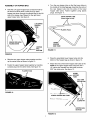
If your tractor hitch has 8" to 10" ground clearance
refer to the instructions for figure 5. If your tractor
hitch has more than 10" ground clearance, refer back
to the instructions for figure 4.
• Place the bent hitch bracket underneath the hitch tubes
and place the straight hitch bracket with hitch pin on top
of the hitch tubes. Fasten together using a 5/16" x 2-1/2"
hex bolt (front), a 5/16" x 2-1/4" hex bolt (rear) and two
5/16" hex lock nuts. See figure 5. The bolts should
straddle the front hitch tube bolt. Do not tighten yet.
• At this time tighten the four bolts fastening the hitch
tubes to the sweeper housing. Next, tighten the two
bolts fastening the hitch tubes together. Finally, tighten
the two bolts fastening the hitch brackets to the hitch
tubes.
• Assemble the two 3/4" spacers onto the hitch pin and
secure the pin with the 1/8" hairpin cotter. See figure 5.
HITCH
BRAG
(STRAIGHT)
HITCH "_ 5/16" HEX LOCK NUTS
BRACKET "_'_'_" HAIRPIN COTTER
FIGURE 5
• Assemble the height adjustment handle to the height
adjustment tube using two curved head bolts, bowed
washers, 5/16" lock washers and 5/16" hex nuts. Do
not tighten yet. See figure 6.
• Assemble the grip onto the height adjustment handle.
See figure 6.
HEIGHT
ADJUSTMENT
HANDLE
5/16" HEX NUT iRIP
5/16"LOCK
WASHER
BOWED
CURVED
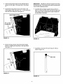
Insert a 5/16" x 3/4" hex bolt through the angle
bracket. Assemble onto the bolt (in order) the spacer
bushing, the height adjustment strap, a 5/16" stan-
dard flat washer and a 5/16" hex lock nut. Tighten.
See figure 7.
_16"x3/4" _16"
HEXBOLT STANDARD
FLAT WASHER
SPACER
BUSHING
5/16" HEX
LOCK NUT
HEIGHT
ADJUSTMENT
STRAP
FIGURE 7
Position the height adjustment handle side to side so
that the tooth lock washer can fit between the handle
and the height adjustment strap. Tighten the nuts
securing the height adjustment handle. See figure 8.
Insert the 5/16" x 3/4" carriage bolt through the height
adjustment handle. Assemble onto the bolt (in order)
the 5/16" tooth-lock washer, the height adjustment
strap, a 5/16" standard flat washer and the plastic
knob. See figure 8.
PLASTIC
KNOB
5/16" STANDARD
FLAT WASHER
5/16" x 3/4"
CARRIAGE BOLT
TOOTH LOCK
WASHER
FIGURE 6
FIGURE 8
6

ASSEMBLY OF HOPPER BAG
Hold the (LH) upper hopper tube so that the hole for
the brace rod faces down. Insert the (LH) upper
hopper tube down through the stitched flap on the left
side of the hopper bag. Repeat for the right hand
upper hopper tube. See figure 9.
(LH) UPPER
HOPPER
TUBE
HOPPER
BAG
BOTTOM
Turn the rear hopper tube so that the brace holes in
the middle of the tube face up. Assemble the ends of
the rear hopper tube onto the ends of the lower
hopper side tubes. Fasten together using plastic
plugs. See figure 11.
REAR HOPPER TUBE
(brace holeson top)
LOWER
HOPPER
SIDETUBE
FIGURE 11
FIGURE 9
Slide the two upper hopper tubes together and line
up the center holes as shown in figure 10.
Fasten the upper hopper tubes together by inserting
a plastic plug into the center holes. See figure 10.
PLASTIC PLUG
i
d_
FIGURE 10
Place the assembled lower hopper tubes into the
bottom of the hopper bag as shown in figure 12.
Attach the ends of the lower hopper side tubes to the
inside of the upper hopper tubes using two 3/8" x
1/2" clevis pins inserted from the inside, and two
3/32" hair cotter pins. See figure 12.
3/32" HAIR
COTTER PIN
\
/
LOWER HOPPER SIDE TUBE
t
3/8" x 1/2"
CLEVIS PIN
HOPPER BAG
BOTTOM
FIGURE 12
7

Insertthebagframestrapintothestitchedsleeve
alongthefrontedgeofthebagbottom.Seefigure
13.
Assemblethebagframestraptotheholesinthe
lowerhoppertubesusingtwo1/4"x1-1/8"clevispins
and3/32"haircotterpins.Seefigure13.
BAG FRAME STRAP
1/4" x 1-1/8"
CLEVIS PIN
FIGURE 13
IMPORTANT: Do not over bend the support rods during
the following step. Over bending wilt cause the spring steel
rods to loose supporting tension.
• Assemble the two hopper support rods as shown in
figure 15. Place the ends of the rods into the upper and
lower hopper tubes, bending the rod just enough to fit
into the holes in the tubes.
FIGURE 15
• Secure the bag corners around the lower hopper
tubes by snapping the bag flaps to the bag bottom.
See figure 14.
SNAP
FIGURE 14
• Assemble a vinyl cap onto each bag arm tube as
shown in figure 16.
VINYLCAP
FIGURE 16
8

• Slidethehopperbagpivotrodthroughtheupper
hoppertubesandthestitchedsleeveonthefrontof
thewindscreen,assemblingahoppermountclamp
andabagarmtubeontotherodoneachsideas
showninfigure17.
HINT:Ifyouhavedifficultyassemblingthehopperbag
pivotrodthroughthestitchedsleeve,tryremoving
thehoppersupportrodsfromtherearofthebag.
• Securetheropetothetopcenterofthehopperbag
frameasshowninfigure19.
HOPPER MOUNT
CLAMP
HOPPER BAG
PIVOT ROD
FIGURE 19
• To assemble the hopper bag to the sweeper, slide
the ends of the bag arm tubes into the ends of the
hitch tubes and secure with two 1/4" x 1-3/4" clevis
pins and 3/32" hairpin cotters. See figure 20.
FIGURE 17
Assemble the two remaining hopper mount clamps
onto the pivot rod on the outside of the bag. Fasten
them to the inside clamps using four 5/16" x 3/4"
carriage bolts and 5/16" (SEMS) hex nuts. Tighten
securely. See figure 18.
• Assemble two palnuts by lightly tapping them onto
the ends of the pivot rod with a hammer. See figure
18.
HINT: To ease assembly of the palnuts, place the bag
on its side on a hard surface. With the bottom end of
the pivot rod against the surface, tap a palnut onto
the top end of the rod. Repeat for other end of rod.
5/16" x 3/4" 5/16" SEMS
CARRIAGE HEX NUT
BOLT
PALNUT
HOPPER
MOUNT
CLAMP
FIGURE 20
• Go to the instructions in the dethatcher owner's
manual to assemble and attach the dethatcher.
FIGURE 18 FIGURE 21
9

ATTACHING SWEEPER HITCH TO TRACTOR
• Place the tractor and sweeper on a flat level surface.
• Set the sweeper height adjustment handle to about the
middle of its adjustment range.
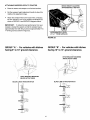
• Attach the sweeper hitch to the tractor hitch, arranging
the 3/4" spacers in one of six possible combinations as
shown in GROUP A and GROUP B diagrams below.
IMPORTANT: To obtain the best performance from your
sweeper, arrange the spacers so that the sweeper bag is
approximately level with the ground and approximately 5" to
7" off the ground as shown in figure 22.
I
BRUSH HEIGHT ADJUSTED
APPROXIMATELY MID-WAY
APPROXIMATELY LEVEL
(5" to 7" FROM SURFACE)
FIGURE 22
\
GROUP "A" - For vehicles with hitches
having 8" to 10" ground clearance.
GROUP "B" - For vehicles with hitches
having 10" to 13" ground clearance.
HITCH BRACKET MOUNTED
ABOVE HITCHTUBES
\
\
\
HITCH BRACKET MOUNTED
BELOW HITCH TUBES
BLACK LINE IS TRACTOR HITCH
BLACK LINE ISTRACTOR HITCH
1
©
©
10

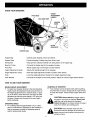
KNOW YOUR SWEEPER
PIVOT ROD
BAG ARM TUBE
HEIGHT
ADJUSTMENT
HANDLE
HOPPER
ROPE
HOPPER BAG
HITCH
BRACKETS \
x
Hopper Bag
Hopper Rope
Windscreen
Bag Arm Tubes
Pivot Rod
Height Adjustment Handle
Height Adjustment Strap
Knob
Hitch Bracket
Collects grass clippings, leaves and debris.
Permits dumping of hopper bag from driver's seat.
Helps prevent collected material from being blown out of hopper bag.
Connects the hopper bag to the sweeper housing.
Allows hopper bag to tilt forward to dump material.
Adjusts the operating height of the sweeper.
Holds the height adjustment handle in position when locked.
Locks the height adjustment handle to the height adjustment strap.
Connects the sweeper to the towing vehicle. Adjusts for various height tractor hitches.
HOW TO USE YOUR SWEEPER
BRUSH HEIGHT ADJUSTMENT
• To adjustyour sweeper brushes to the best operating
height, loosen the adjustment knob and pushdown on
the height adjustment lever toraise the brush, or push
up on the lever to lower the brush. See figure 22. Best
adjustment is when the brush setting is 1/2" down into
the grass. Always mow the grass to an even height
before sweeping.
SWEEPING SPEED
• Try a starting speed ofapproximately 3 m.p.h. (third
gear on most tractors). Depending on the conditions,it
may be necessary to adjustthe sweeping speed in
order to achieve best results.
DUMPING OF SWEEPER
• Your sweeper can be dumped easily without getting
off of the rider or tractor. Simply pull the rope forward
to dump the hopper. Always empty hopper after each
use.
CAUTION: Never attach the hopper rope to
any part of your body or clothing! Never hold
onto the rope while towing the sweeper!
Attach the rope to the towing vehicle to keep it
away from wheels and rotating parts.
11
CAUTION: Keep sweeper away from fire.
Excessive heat can damage the brushes and
hopper bag and could cause the bag and its
contents to burn.

CUSTOMER RESPONSIBILITIES
• Read and follow the maintenance schedule and the
procedures listed in the maintenance section.
MAINTENANCE SCHEDULE
Fill in dates as you
complete regular service.
Check for loose fasteners
Check for worn or dama,qed parts
Lubricate brush shaft bearings
Lubricate wheel beadn,qs
Clean Sweeper
Clean/Lubricate gears
X
X X
X
X
X X
X
Service Dates
SCHEDULED MAINTENANCE
• Clean the sweeper after each use.
Inspect for worn or damaged parts, such as brushes
and wheels.
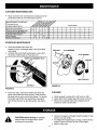
• Lubricate the brush shaft bearing twice a year with a
few drops of light weight oil. See figure 23.
OIL BEARINGS HERE
HEIGHT ADJUSTMENT SLOT
FLAT WASHER.._
FIGURE 23
HEXBOLT
Every two years, remove the wheels and clean the
gears found inside the wheel housing. After cleaning,
lubricate with an even coat of light grease. To remove
the wheel, pop off the hub cap using a screwdriver
and remove the lock nut and flat washer. See figure
24.
HEXBOLT
SPACER
FLAT WASHER
FLAT WASHER
HUBCAP
HEX LOCK NUT
FIGURE 24
CLEANING
• Clean sweeper housing with a soft brush or cloth.
• Clean debris from hopper bag with a brush or broom.
• Remove any material which has wrapped around
brushes or ends of brush shaft.
&
CAUTION: Before storing the sweeper,
always empty the hopper bag to avoid
spontaneous combustion.
12
• Clean the sweeper and hopper bag thoroughly to help
prevent rust and mildew.
• To collapse the hopper bag for storage, remove the two
hopper support rods from the rear of the hopper.
• Store in a dry area.

BRUSH REPLACEMENT
NOTE: Brush replacement should be done one brush at a
time.
• Remove the hopper bag from the sweeper.
• Loosen the hex bolts and lock nuts on two single
brush retainers which clamp one brush to the double
brush retainers. Do Not loosen or remove the bolts
which fasten the double brush retainers to the brush
shaft. See figure 25.
• Slide the brush out of the retainers, noting on which
side of the brush the bristles overlap. See figure 25.
• Install new brush, making sure the bristles overlap on
the same side of the brush as before. See figure 25.
BRUSH ROTATION
OVERLAP
BRUSH BRISTLES
SHAFT
SINGLE
_BRUSH
RETAINER, _
BRUSH
OVERLAP
BRISTLES
BRUSH ROTATION_p
FIGURE 25
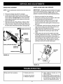
WHEEL GEAR AND PAWL SERVICE
IMPORTANT: Do not remove both wheels at the same
time to avoid mixing of parts. (The R.H. and L.H. ratchet
gears are not interchangeable.) Make notes on the
position of washers and snap rings during disassembly.
• Remove one wheel from the sweeper.
• Remove the retaining rings and washers which hold
the ratchet gear onto the brush shaft.
• Remove the gear by sliding it off the brush shaft.
(Look for the drive pin, which may fall out of the
brush shaft when the ratchet gear is removed.) See
figure 26.
• To reassemble, insert the drive pin through the hole
near the end of the brush shaft. Make sure the pin
slides back and forth easily in the shaft.
• Lightly grease the shaft and fill the ratchet gear with
grease. Assemble the ratchet gear back onto the
shaft.
• Lightly grease the axle and the wheel's gear teeth
and then reassemble the wheel. The brushes should
rotate only during forward rotation of the wheel. If
the brushes are driven (rotated) by both forward and
reverse rotation of the wheel, the drive pin is jam-
ming in the ratchet gear. Disassemble to clean and
lubricate the drive pin and the ratchet gear.
RATCHET
• GEAR
.-
FIGURE 26
Wheels skid when sweeping.
• Brushes set too low.
• Brushes are jammed
• Wheels are jammed.
• Adjust height till brushes are 1/2"
down into grass.
• Stop sweeper. Remove obstruction.
• Remove one wheel at a time to check
for obstruction or damage. Refer to
Service and Adjustments section.
13

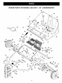
REPAIR PARTS FOR MODEL 486.24212 - 46" LAWNSWEEPER
77
/
44,_
45
49
0
66
62 /
/
61 60
61
26 43
72
\\
85
74
29
29
70
50/
20
13\
-5
9
' I 29
7
2
18
75
\ 4
/
39
30
79 _\
47
_21
43
/
34
33 27
/ 41
31
48
35
36
/
33
37
60
14

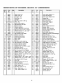
REPAIR PARTS LIST FOR MODEL 486.24212 - 46" LAWNSWEEPER
Ref. Part Qty Description Ref. Part Qty. Description
No. No. No. No.
1 48602 1 Hitch Tube, R.H. 45 46735 1
2 48601 1 Hitch Tube, L.H. 46 47477 1
3 24950 1 End Plate, R.H. 47 48726 2
4 24951 1 End Plate, L.H. 48 48401 1
5 24953 1 Wrapper 49 48366 2
6 43175 2 Bolt, Hex 1/4-20 x 1/2" Lg. 50 24189 1
7 C-9M5732 14 Rivet, Pop 51 43938 2
8 24871 1 Brace, Rear Support 52 43737 1
9 43182 2 Bolt, Hex 5/16-18 x 3/4" 53 44481 2
10 23826 1 Bracket, Angle 54 24979 1
11 23336 2 Washer, Special 55 23687 1
12 64521 1 Height Adjustment Tube Ass'y. 56 24192 1
13 44947 2 Bolt, Cvd. Hd. 5/16-18 x 1-5/8" Lg. 57 24981 1
14 44695 2 Washer, Bowed 1" x .32" x .06" 58 46781 2
15 43086 8 Lock Washer, 5/16" 59 46823 1
16 43083 6 Nut, Hex 5/16-18 Thread 60 44985 2
17 R19212113 2 Washer, 5/8" SAE 61 45088 4
18 1629-56 2 Retainer, Dust Cover 62 46782 2
19 44910 2 Bushing, Brush Shaft 63 43224 1
20 24929 1 Brush Shaft 64 23331 4
21 48600 4 Brush, 46" 65 46980 4
22 43012 8 Bolt, Hex 1/4-20x 3/4" Lg. 66 ::{19111116 2
23 43013 14 Nut, Hex Lock 1/4-20 Thread 67 43720 1
24 23580 4 Retainer, Brush (Double) 68 43080 5
25 23581 8 Retainer, Brush (Single) 69 43081 2
26 44008 2 Washer, Flat 1-1/8" x .78" x .025" 70 43943 1
27 47046 2 Dowel Pin (Drive) 71 44732 1
28 44692 4 Bolt, Hex 5/16-18 x 1/2" Lg. 72 46816 1
29 43064 10 Nut, Hex Lock 5/16-18 Thread 73 23368 2
30 44911 2 Spacer, .39 I.D". x 1-1/4" O.D. x .5" 74 43343 1
31 44006 2 Washer, Flat .849" x .598" x .025" 75 43055 6
32 46219 2 Spacer, .78 I.D". x 1-1/4" O.D. x .5" 76 46867 2
33 1650-21 4 Ring, Retaining .594" 77 44917 2
34 44007 2 Washer, Shim 1-1/8" x .594" x .025" 78 48402 3
35 141 2 Washer, Flat 1-1/2" x .375" x .062" 79 48365 2
36 1038 2 Nut, Nylock 3/8-24 Thread 80 43070 2
37 2674-32 2 Hub Cap 81 44215 4
38 44961 2 Bolt, Hex 3/8-24x 3-1/4" Lg. 82 :{19171616 1
39 23400 3 Bushing, Spacer 83 43082 1
40 48652 1 Gear, Pinion R.H. (not shown) 84 44292 1
41 48651 1 Gear, Pinion L.H. 85 44230 1
42 43661 4 Bolt, Hex 1/4-20 x 1" Lg. 86 43350 1
43 64559 2 Ass'y, Dust Cover 87 142 1
44 46734 1 Tube, Upper Hopper R.H. 88 23684 1
48825 1
Tube, Upper Hopper L.H.
Tube, Rear Hopper
Tube, Lower Hopper Side
Hopper Bag
Clevis Pin, 3/8" x 1/2"
Strap, Bag Frame
Rod, Hopper Support
Hopper Rope
Cap, Vinyl
Strap, Height Adjustment
Bracket, Hitch
Bracket, Hitch (Straight)
Handle, Height Adjustment
Tube, Bag Arm
Rod, Hopper Bag Pivot
Wheel & Tire Ass'y. (with bearings)
Wheel Bearing
Bolt, Hex 5/16-18 x 3" Lg.
Bolt, Hex 5/16-18 x 2-1/4" Lg.
Clamp, Hopper Mount
Nut, Hex 5/16-18 (SEMS)
Washer, Flat (5/16) 11/32" x 11/16"
Knob, Wing 5/16-18 Thread
Bolt, Carriage 5/16-18 x 3/4" Lg.
Washer, Flat 5/16" Std. Wrt.
Grip, Height Adjust
Washer, Tooth Lock 5/16"
Pin, Hitch
Tube, Hitch Spacer
Hairpin Cotter, 1/8" #4
Hairpin Cotter, 3/32" #3
Pin, Clevis 1/4" x 1-3/4" Lg.
Palnut, 3/8"
Plastic Plug
Clevis Pin, 1/4" x 1-1/8"
Washer, 3/8" Std. Wrt.
Bolt, Carriage 5/16-18 x 1-3/4"
Washer, 1/2"
Nut, Hex Lock 3/8-16
Bolt, Hex 5/16-18 x 2-1/2"
Spring
Bolt, Carriage 3/8-16 x 1"
Pin, Cotter 1/8" x 3/4"
Bracket, Hitch Pin
Owners Manual
15

no matter who made it, no matter who sold it!
1-800-4-MY-HOME sMAnytime, day or night
(1-800-469-4663)
www.sears.com
To bring in products such as vacuums, lawn equipment and electronics
for repair, call for the location of your nearest Sears Parts & Repair Center.
1-800-488-1222 Anytime, day or night
www.sears.com
1-800-366-PART 6 a.m. - 11 p.m. CST,
(1-800-366-7278) 7 days a week
www.sears.corn/partsdirect
To purchase or inquire about a Sears Service Agreement:
For the replacement parts, accessories and owner's manuals
that you need to do-it-yourself, call Sears PartsDirect sM!
1-800-827-6655
7 a.m. - 5 p.m. CST, Mon. - Sat.
Para pedir servicio de reparaci6n a domicilio,
y para ordenar piezas con entrega a domicilio:
1-888-SU-HOGAR s_
(1-888-784-6427)
Au Canada pour service en frangais:
1-877-LE-FOYERSM
(1-877-533-6937)
[ }
HomeCentral°°
® Registered Trademark / _MTrademark of Sears, Roebuck and Co.
© Sears, Roebuck and Co. ® Marca Registrada / _M Marca de Fk_brica de Sears, Roebuck and Co.
-
 1
1
-
 2
2
-
 3
3
-
 4
4
-
 5
5
-
 6
6
-
 7
7
-
 8
8
-
 9
9
-
 10
10
-
 11
11
-
 12
12
-
 13
13
-
 14
14
-
 15
15
-
 16
16


Craftsman 486.24212 Owner's manual
- Category
- Garden tools
- Type
- Owner's manual
- This manual is also suitable for
Ask a question and I''ll find the answer in the document
Finding information in a document is now easier with AI
Related papers
-
Craftsman 486.24237 Owner's manual
-
-
-
-
-
-
-
-
-
Other documents
-
Bissell Natural Sweep Assembly
-
 Ohio Steel 42LS User guide
-
 Ohio Steel 50SWP26 User manual
-
Swisher 12048 Owner's manual
-
 Ohio Steel RT350 User manual
-
 Yard Commander LABV0900 User manual
-
Agri-Fab 45-0218 User manual
-
-
-
 Ohio Steel 42LS Installation guide


