CABASSE ALTURA - AMBROISE 3 Owner's manual
- Category
- Soundbar speakers
- Type
- Owner's manual

ALTURA
notice d’installation des enceintes acoustiques
loudspeakers owner’s manual
betriebsanleitung für lautsprecherboxen
riva
•
bahia
•
sena
•
largo
linea colonne
•
linea sur socle
www.cabasse.com
Cab notice Altura gamme 2005-4 28/10/05 9:59 Page 1
Page is loading ...
Page is loading ...
Page is loading ...
Page is loading ...
Page is loading ...
Page is loading ...
Page is loading ...
Page is loading ...
Page is loading ...
Page is loading ...

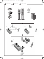
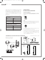
UNPACKING
1
After opening the top carton flaps, remove the grille. Then
fold the carton flaps right back and invert the carton contents.
Lift the carton clear of the contents and remove the inner pac-
kaging from the speakers. We suggest you to retain the packing
for future use.
POSITIONING
Speakers positioning
Our speakers have been designed to function in a vertical posi-
tion. Under these conditions, the polar response is most uni-
form
2
.
The majority of our models are delivered with a set of decou-
pling spikes or cones
3
, these accessories are to be screwed in
the inserts under the cabinets. These accessories ensure the
stability of the speaker while limiting resonance coming from
certain types of grounds like wood floors.
Speakers are delivered with a front grille to protect drivers. It
is possible to use them without this front grille, but we recom-
mend this protection to be kept on to prevent accidental dama-
ge to the drivers
4
.
Powerful drivers generate magnetic fields that can extend
beyond the boundaries of the speaker cabinet. We recom-
mend you keep magnetically sensitive articles (TV, computer
screen, computer discs, audio and video tapes, swipe cards...)
at least 1.5 ft (50 cm) away from the speaker. Cabasse centre
speakers or the ones marked «TV» are not concerned with
this, being magnetically shielded.
Positioning speakers in a room
In addition to vertical position of the speakers themselves,
their location in the listening room, as well as the acoustical cha-
racteristics of the room, are also very important. As it is impos-
sible to indicate a typical location of speaker systems without
a few tests, we suggest several general rules that are impor-
tant to apply in order to obtain the best listening results.
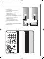
Optimal positioning for a 2.0 or stereo system
5
■ For the ideal positioning of your speakers follow diagram.
If «d» is the distance between the two speakers, this distance
must be higher than 5 ft (1.5 m) and the two speakers must be
at equal distance from the listening area which forms with
them an equilateral triangle.
■ The drivers must be directed towards the listening area.
■ The speakers should be located so that their diffusion follows
the longest dimension of the room.
■ Generally speaking it is better to avoid putting the speakers
in the corners of a room as this amplifies the low frequencies
and tends to enhance the room resonances. If possible it is
better to place the speakers at least 8 inches (20 cm) from
the walls.
■ Moreover, in order to obtain a more accurate frequency res-
ponse, it is recommended to raise a compact speaker from
12 to 16 inches (30 to 40 cm) above the floor by placing them
on stands. The tweeters of the speakers must be roughly at
the same height of the listener’s ear when the listener is in sit-
ting position.
■ No solid object or piece of furniture should be placed between
the speakers and the listener. An effect of mask, even partial dis-
turbs completely the sound reproduction as it attenuates the
high frequencies and also, in most cases, the midrange fre-
quencies.
■ Placing the speakers in niches is not recommended. Unless
designed for this application, bookshelf placement will alter the
frequency response of the speaker, especially in the low fre-
quencies. If a bookshelf location cannot be avoid, the speaker
should be set up to minimize various resonance, and the visible
part of the grille must be outside the niche.
Optimal positioning for a 2.1
or stereo with a subwoofer system
6
For a stereo listening with 2 speakers or 2 satellites and 1 sub-
woofer, we recommend you to place the subwoofer in the
front listening area. The placement of the subwoofer against
a wall reinforces the low frequencies and limit the reflections
from 80 to 200 Hz. However to obtain the best results, it is
always necessary to carry out tests according to the acoustic
of the room.
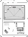
Optimal positioning for a 5.1
or home theatre system
7
Setting up a multi-channel Audio-Video system requires great
care when positioning the specific AV speakers.
■ The centre speaker should be placed as close as possible to
the screen and where it sounds best from your listening spot
while offering the optimal picture/dialogues cohesion. Theo-
retically, the screen should be located within a virtual triangle
formed by the acoustical centres of the main speakers and the
centre speaker. Practically speaking, this means that the prin-
cipal speaker should be placed above the screen if the main
speakers are below it, and below the screen if the main spea-
english
Thank you very much for choosing Cabasse speakers.
Please read carefully these instructions before setting up your speakers.
BAHIA
•
RIVA
•
SENA
•
LARGO
Cab notice Altura gamme 2005-4 28/10/05 9:59 Page 12

kers are above. The centre speaker should also, if possible, be
set slightly back from the others, so that it is located at the same
distance from the listener as the main speakers.
■ The rear speakers or surround should be placed against the
side walls, at listening height. They should not be positioned
far behind the listening zone.
■ The subwoofer should be placed in the front listening area,
its position against a wall reinforces the extreme low register and
limits the reflections between 80 and 200 Hz. However to
obtain the best result, it is always necessary to carry out tests
according to the acoustics of the room.
Your AV processor enables the adjustment in level and delay of
each of the 5/6/7 channels of your system. Fine-tuning is neces-
sary to obtain a perfect sound stage.
Turn off all the amplifiers before interconnecting them to the
loudspeakers. In order to connect loudspeakers properly, it is
most important to keep in mind the following two factors:
cable section and phase.
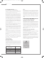
CONNECTION
Cable section
To get the full sonic potential of Cabasse loudspeakers and
avoid power losses, the cables connecting the speakers to the
power amplifier must have the lowest possible electrical resis-
tance. To help you in choosing the correct cable gauge, follow
diagram.
Phase
In order to maintain the phase relationship and frequency
balance of the loudspeaker system, both loudspeakers must be
properly connected to the power amplifier. When properly
connected, the cones of the drivers of both loudspeakers will
move in the same direction when driven by identical speakers
will move in the same signals. If the cones move in opposite
directions, the resulting out of phase signals will create a per-
ceptible power loss, particularly in the low frequencies. The
stereophonic message will also be degraded. Amplifier and
speaker manufacturers typically indicate connection polarity in
one of two ways: red and black or plus and minus. In either
case, always connect red or plus to red or plus and black or
minus to black or minus. Connections should be identical for
both channels. To check that the speakers are in correct pha-
se, switch the system to mono while music is being played. if
the amplifier does not have a phase inversion switch, it will
be necessary to change over the connections on one only of the
loudspeakers. If in correct phase, the image should be dis-
tinctly located between the loudspeakers with a slight loss of
bass and low midrange level. If the image is confused and not
centrally located and there is a drastic loss of bass and low
midrange level, recheck your connections.
HOME THEATER CONNECTIONS WITH
AN ACTIVE SUBWOOFER
Subwoofer positioning
With a crossover point below or around 150 Hz, the installa-
tion position of subwoofers is not limited as human ears and
brains are not able to identify the emitting point of such low
frequencies. To get the best result, it is recommended to try dif-
ferent positions and choose the one giving the best response
in the low frequencies, taking into account the room acoustics.
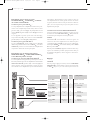
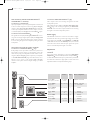
Hooking up the subwoofer
2 possibilities are offered to connect the subwoofer with your
system:
■ the low level one requiring the use of the
Cinch RCA LINE IN
8
and
LINE OUT
9
terminals and shielded coaxial connectors,
■ the high level one requiring the use of the
HIGH LEVEL
INPUT
0
and
HIGH LEVEL OUTPUT
-
terminals and standard
loudspeaker cables.
The inputs are stereo ones, the mix of the
L (left)
and
R (right)
low frequencies being done by the amplifier of the subwoofer.
If the input signal is already mono, only one input
L (left)
or
R
(right)
should be used.
S1
english
Attention,
before operating the unit,
be sure that the
operating voltage
of your unit is identical
with that of your local
power voltage.
Lenght between recommanded
amplifier and loudspeakers section
4.5 m 1.5 mm
2
6 m 2 mm
2
7.5 m 2.5 mm
2
9 m 3 mm
2
12 m 4 mm
2
Cab notice Altura gamme 2005-4 28/10/05 9:59 Page 13

english
Interconnections with the Cinch RCA LINE IN
8
and LINE OUT
9
connectors
■ Connections to the LINE IN
8
If your preamplifier or your integrated amplifier is fitted with
a stereo low-level output, then connect its
L (left)
and
R (right)
outputs to the
L (left)
and
R (right) LINE IN
0
inputs of the sub-
woofer. If your amplifier offers a one mono output, connect it
to either the
L (left)
or the
R (right)
subwoofer
LINE IN
0
inputs.
■ Connections from the LINE OUT
9
The signal from the
L (left)
and
R (right) LINE OUT
9
connec-
tors is the one being brought in by the
L (left)
and
R (right) LINE
IN
8
connectors filtered at 40 Hz. These outputs can thus
be used to bring the signal to the amplifier powering the main
loudspeaker.
Interconnections with the speaker terminals
■ Connections to HIGH LEVEL INPUT
0
plugs
If the preamp section of your Hi Fi or audio-video system is not
fitted with a low level output, you should then connect the
subwoofer by using its loudspeaker terminals. When connec-
ting the
L (left)
and
R (right)
speaker outputs of your amplifier
to the
HIGH LEVEL INPUT
0
plugs of the subwoofer, be care-
ful not to cross (-) and (+) cord of either
L (left)
or
R (right)
channel. Such a phase inversion might damage your main
amplifier.
■ Connections HIGH LEVEL OUTPUT
-
plugs
These outputs can be used to bring the signal to the main
loudspeaker systems.
The signal from the
L (left)
and
R (right) HIGH LEVEL OUT-
PUT
-
plugs is the one being brought in by the
HIGH LEVEL
INPUT
0
connectors. These outputs can thus be used to bring
the signal to the main loudspeaker systems.
Power supply
The
AC in
=
cord must be connected to the mains to supply
the subwoofer. The selection of the right voltage 115V -230 V
is done with 115V-230V
q
. Switch
POWER
w
, on
STAND BY
or
ON
. With the switch on the
STAND BY
position, the unit will
mute after a few minutes without input signal. The system
turns on automatically when signal comes back.
Adjustments
■ LEVEL
e
For a first volume adjustment, position the
CROSSOVER
FREQUENCY
r
at around 120 Hz, and turn slowly the
LEVEL
e
clockwise from minimum level up to a position where you feel that
the subwoofer sound level is appropriate. A check of the level
adjustment will be necessary after following steps.
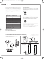
Position Ways Drivers complement
Altura RIVA bookshelf 2 DOM50-17M18LB2
main speaker / surround /stand
Altura
BAHIA floorstanding 3 DOM50 - 13M15M2
main speaker 2 x 17M18LB2
Altura
LARGO floorstanding 1 30M40
active subwoofer
Altura SENA on / under 2 DOM50
center TV 2x 13M15M2TV
Altura
LINEA floorstanding 2.5 DOM50
floorstanding 2 x 13MTR5
Altura
LINEA bookshelf 2.5 DOM50
on base / on wall 2 x 13MTR5TV
Cab notice Altura gamme 2005-4 28/10/05 9:59 Page 14

english
■ CROSSOVER FREQUENCY
r
This potentiometer adjusts the cut-off frequency which deter-
mines the working bandwidth of the subwoofer. This adjust-
ment should be done according to the specifications of the
main speakers and the room acoustics. Choose the best fre-
quency after various listening tests.
■ PHASE
t
For a better sound integration of the subwoofer in the main
system, the
PHASE
t
of the subwoofer might have to be
inverted (180° position), depending on the distance between
the subwoofer and the main speakers. You have to check the
PHASE
t
each time you move your speakers and each time
you adjust the
CROSSOVER FREQUENCY
r
.
Attention, if you use 2 subwoofers, both phase switches must
be on the same position.
Our web site
www.cabasse.com
will give you the specific adjust-
ments we recommend for the use of our active subwoofers.
MAINTENANCE
The Altura cabinets are made of medium density fiber panels,
veneered with natural wood and protected by 4 coats of var-
nish. This hi-tech veneer does not require any specific care. Use
a wet cotton waste for cleaning, or any cleaning device for
wood or plastic.
Because of technical improvements already under way in our constant search for optimum quality,
Cabasse
reserves the right to modify all the models presented in specification sheets, advertising materials and manuals without prior notice.
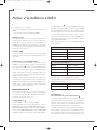
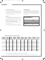
ACTIVE SUBWOOFER
ALTURA LARGO
Pulsed sound pressure 121dB
Phase switch 0° normal
180° reverse
In put 2 low level- 2 hight level
Voltage 115/ 230 V AC-50/ 60Hz
Maximum power
consumption 165W
Sensivity
Cross-over
Frequency Nominal Minimum Power Peak Standard Dimensions Weight
1W/1m points response impedance impedance handling power finish h
x
w
x
d
(dB) (Hz) (Hz) (ohms) (ohms) (Watts) (Watts)
92 2,500 60-25,000 8 4.2 100 700 wild cherry 44 x 32 x 23 cm 11 kg
santos 17.3”x 12.6”x 9” 24 lbs
94 700- 50-25,000 8 3.2 120 840 wild cherry 115 x 38 x 26 cm 27 kg
2,500 santos 45.3”x 15”x 10.2” 59 lbs
Active adjustable 30-200 Active Active 250 750 wild cherry 51
x 55 x 35 cm 29 kg
santos 20.1”x 21.7”x 13.8” 64 lbs
92.5 2,700 60-25,000 8 3.5 100 700 wild cherry 23
x 55 x 34 cm 15 kg
santos 9.1”
x 21.7”x 13.4” 33 lbs
93 500- 80-25,000 8 3.7 100 700 wild cherry 114
x 24 x 11.8 cm 16 kg
2,500 santos 44.9”
x 9.4”x 4.6” 35 lbs
93 500- 80-25,000 8 3.7 100 700 wild cherry 46
x 24 x 11.8 cm 10.5 kg
2,500 santos 18.1”
x 9.4”x 4.6” 23 lbs
SPECIFICATIONS & TECHNICAL DATA
Cab notice Altura gamme 2005-4 28/10/05 9:59 Page 15

english
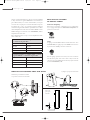
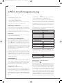
INSTALLATION
The components of your system:
- 2, 3, 5 (with eventually other ALTURA speakers), 6 or 7 LINEA
- 1 or 2 LARGO Cabasse active subwoofer
- 1 Max Cabasse module if the processor of your audio video
amplifier doesn’t include a 2.1 set-up (subwoofer for stereo
reproduction)
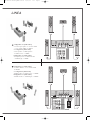
LINEA speaker on base plinth version
The wall mountable version of the LINEA requires 2 brackets
to be positioned on a wall, either in a vertical position (A) or
a horizontal position (B). The two pins -silent block- allows the
LINEA speaker to be positioned horizontally on/below a TV or
on a furniture such as bookshelf (C).
For vertical positioning on a bookshelf, use the supplied base
(D)
Floorstanding LINEA
The stand version is supplied with adjustable spikes for a per-
fect stability even if the floor is not horizontal.
Positioning of LINEA SYSTEM
Positioning of the speakers: if possible, try to match with the
drawing, with the LARGO subwoofer in the front area
facing the listening spot. Its position against a wall reinforces
the extreme low register and limits the reflections between 80
and 200 Hz. However to obtain the best result, it is always
necessary to carry out tests according to the acoustics of the
room.
Attention, on some sensitive TV-sets, the magnetic shielding of
the LINEA TV speaker might not be effective enough because
of the radiations throughout the diaphragm of the tweeter.
You should then place the LINEA TV speaker 10 cm away from
the top of the TV.
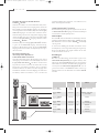
CONNECTIONS
It is imperative to respect the correct phasing when connecting:
+ to + red and - to - black.
Configuration 2.1
2 LINEA speakers + 1 LARGO subwoofer
Connect with speaker cables the amplifier outputs to the terminals
HIGH LEVEL INPUT L (left) and HIGH LEVEL INPUT R (right) of
the LARGO subwoofer and connect the outputs HIGH LEVEL
OUTPUT L (left) and HIGH LEVEL OUTPUT R (right) of the LAR-
GO subwoofer to the LINEA speakers inputs.
Configuration 5.1
5 LINEA speakers + 1 LARGO Subwoofer or 2 main speakers
+ 3 LINEA speakers + 1 LARGO subwoofer
When the processor of your audio video amplifier includes a
2.1 set-up (subwoofer for stereo reproduction), connect each
speaker output of the 5.1 amplifier directly to the matching
LINEA speaker (front right, front left, centre, surround...).
Connect the subwoofer CINCH RCA output of the amplifier to
one of the CINCH-RCA LINE IN terminals of the LARGO sub-
woofer.
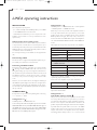
Then adjusts the set-up menu of your audio video amplifier:
* Adjustment in SMALL or LARGE, according to their ability in
reproducing deep low frequencies.
Some audio video amplifiers require these information:
If your audio video has an adjustable crossover frequency, the
adjustement will be 80 Hz.
Configuration 5.1
with the Max Cabasse module
The processor of some audio video amplifiers doesn’t include
a 2.1 setup (subwoofer for stereo reproduction), in this case
you will need a Max Cabasse module (available separately).
Connect 2 sets of inputs of the Max Cabasse module to the
speaker outputs L/left and R/right of the audio video amplifier,
in parallel with the speaker cables connected to the LINEA
speakers. The 2 inputs can be connected to any main speaker
outputs of the audio video amplifier, but be very careful in
not mixing polarities: always connect + to + (or red to red and
S5
SUBWOOFER ONLY
SUBWOOFER STEREO YES
2 main speakers + 3 LINEA speakers
+ 1 LARGO subwoofer
FRONT SMALL or LARGE *
CENTER SMALL
SURROUND SMALL
SUBWOOFER / LFE YES
5 LINEA speakers + 1 LARGO subwoofer
FRONT SMALL
CENTER SMALL
SURROUND SMALL
SUBWOOFER / LFE YES
S4
S3
S1
S2
LINEA operating instructions
Cab notice Altura gamme 2005-4 28/10/05 9:59 Page 16

english
black to black). Connect the CINCH RCA output of the Max
Cabasse module to one of the CINCH RCA LINEIN post of
the LARGO subwoofer with a shielded interconnect cable.
Connect the subwoofer CINCH-RCA output of the audio video
amplifier to the second CINCH RCA LINE IN post of the LAR-
GO subwoofer.
Then adjusts the set-up menu of your audio video amplifier:
ADJUSTMENTS
OF THE LARGO SUBWOOFER
Crossover frenquency
In any cases configuration 2.1 or configuration 5.1, the adjust-
ment of frequencies CROSSOVER FREQUENCY is positioned
as follows:
Level
The adjustment of the LEVEL will depend upon room positio-
ning, type of amplifier, etc. With the LARGO subwoofer, the ave-
rage position of the LEVEL control is as follows:
For an optimum adjustment of this level, we advise you to car-
ry it out starting from a stereo source (CD).
To adjust the level of the low frequency effect channel, (LFE)
do not modify the sound level of the LARGO subwoofer but go
into the set-up menu of your audio video amplifier 5.1 and
adjust the SUBWOOFER / LFE channel.
2 main speakers + 3 LINEA speakers
+ 1 LARGO subwoofer + 1 Max module
FRONT LARGE
CENTER SMALL
SURROUND SMALL
SUBWOOFER / LFE YES
5 LINEA speakers + 1 LARGO subwoofer
+ 1 Max module
FRONT LARGE
CENTER SMALL
SURROUND SMALL
SUBWOOFER / LFE YES
Brackets for on wall vertical
and horizontal positioning
(C) Pins for horizontal use on shelf
(D) Base
for vertical use
on shelf
ASSEMBLING THE LINEA ON BASE ACCESSORIES
(A)
(B)
Cab notice Altura gamme 2005-4 28/10/05 9:59 Page 17
Page is loading ...
Page is loading ...
Page is loading ...
Page is loading ...
Page is loading ...
Page is loading ...
Page is loading ...
-
 1
1
-
 2
2
-
 3
3
-
 4
4
-
 5
5
-
 6
6
-
 7
7
-
 8
8
-
 9
9
-
 10
10
-
 11
11
-
 12
12
-
 13
13
-
 14
14
-
 15
15
-
 16
16
-
 17
17
-
 18
18
-
 19
19
-
 20
20
-
 21
21
-
 22
22
-
 23
23
-
 24
24


CABASSE ALTURA - AMBROISE 3 Owner's manual
- Category
- Soundbar speakers
- Type
- Owner's manual
Ask a question and I''ll find the answer in the document
Finding information in a document is now easier with AI
in other languages
Related papers
-
CABASSE SANTORIN 21 Owner's manual
-
CABASSE Surf Owner's manual
-
CABASSE KARISSIMA Owner's manual
-
-
-
CABASSE Minorca MC40 User manual
-
-
-
-
Other documents
-
 mivoc HYPE 10 User manual
-
Magnat Audio Interior 5001A Owner's manual
-
Magnat Audio Interior 5001A Owner's manual
-
 Bowers & Wilkins DM 605 User manual
-
Bowers & Wilkins PV1 User manual
-
Pioneer S-7EX User manual
-
MTX CT12SW Owner's manual
-
-
Q Acoustics 2010i User manual
-
OSD Audio ACOUSTIC-10 Owner's manual

