Skytronics 952.969 Mixer Amplifier 4 Channel 60 W Specification
- Category
- AV receivers
- Type
- Specification

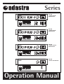
Series
952.975 SLAVE AMPLIFIER 120W
MIC 3 / AUX
010
952.972 MIXER AMPLIFIER 120W
MIC 3 / AUX
010
952.969 MIXER AMPLIFIER 60W
952.966 MIXER AMPLIFIER 30W
Operation Manual
952.966
3 CHANNEL 30W RMS
MIXER AMPLIFIER
952.969
4 CHANNEL 60W RMS
MIXER AMPLIFIER
952.972
4 CHANNEL 120W RMS
MIXER AMPLIFIER
952.975
120W RMS SLAVE AMPLIFIER

Certificate of conformity
We: Adastra Electronics Ltd., Containerbase, Barton Dock Road, Manchester, M41 7BQ
Declare that the product:
Adastra 900 series amplifier
Has been manufactured in conformity with the following standards and specifications:-
• Low Voltage Directive:
EN 60065:1993, (BS.EN 60065:1994)
• E.M.C Directive: Emission: EN 55103-1:1996, (BS.EN 55103-1:1997)
Immunity: EN 50104-2:1996, (BS.EN 55103-2:1997)
and complies with the requirements of:-
• Low Voltage Directive:
Reference 73/23/EEC as amended by Directive 93/68/EEC
• E.M.C Directive: Reference 89/336/EEC as amended by directive 92/31/EEC
Issued by: Adastra Electronics Ltd., Containerbase, Barton Dock Road, Manchester, M41 7BQ on 25/9/2000
Authorised Signatory:
Phil Williams, Managing Director
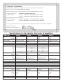
Specifications for the Adastra 900 series of amplifiers
Output: Rated 30W 60W 120W 120W
10% THD 40W 70W 160W 160W
Output regulation
< 2dB, no load to full load < 2dB, no load to full load < 2dB, no load to full load < 2dB, no load to full load
Speaker output Balanced floating 8Ω Balanced floating 8Ω Balanced floating 8Ω Balanced floating 8Ω
100V 333Ω 166Ω 83Ω 83Ω
Line output (stereo) 600Ω, 1V (0dB) 600Ω, 1V (0dB) 600Ω, 1V (0dB) 600Ω, 1V (0dB)
Slave output (mono) 600Ω, 1V (0dB) 600Ω, 1V (0dB) 600Ω, 1V (0dB) 600Ω, 1V (0dB)
Input sensitivity Mic1
1.5mV (-56.4dBV), balanced 1.5mV (-56.4dBV), balanced 1.5mV (-56.4dBV), balanced -
Mic2
1.5mV (-56.4dBV), unbalanced 1.5mV (-56.4dBV), unbalanced 1.5mV (-56.4dBV), unbalanced
-
Mic3
-
1.5mV (-56.4dBV), unbalanced 1.5mV (-56.4dBV), unbalanced
-
Aux
-
300mV (-10.4dBV), unbalanced 300mV (-10.4dBV), unbalanced
-
Line
300mV (-10.4dBV), unbalanced 300mV (-10.4dBV), unbalanced 300mV (-10.4dBV), unbalanced
-
Input impedance Mic 5kΩ 5kΩ 5kΩ -
Aux/line 10kΩ 10kΩ 10kΩ -
Input Connectors Mic1 XLR
(1=Gnd, 2=+IN, 3=-IN)
XLR
(1=Gnd, 2=+IN, 3=-IN)
XLR
(1=Gnd, 2=+IN, 3=-IN)
-
Mic2,3
1
/4" (6.3mm) jack socket
1
/4" (6.3mm) jack socket
1
/4" (6.3mm) jack socket -
Aux RCA (phono) socket RCA (phono) socket RCA (phono) socket RCA (phono) socket
Frequency Response 100Hz - 12kHz ±3dB 100Hz - 12kHz ±3dB 100Hz - 12kHz ±3dB 100Hz - 12kHz ±3dB
Disctortion THD+N = < 2% @ 1KHz, on rated power
Signal to Noise Ratio All volume controls ccw: 92dB Master max & all input vol. Min: 75dB Mic 1,2,3: 70dB Aux & Line: 75dB
Tone control Bass: +0dB, -10dB @ 100Hz Treble: +0dB, -10dB @ 10kHz
Protection circuits Current limiter, thermal protection AC/DC fuses
Muting function Mic 1 overides other inputs when VOX switch is ON. (-40dB attenuation)
Power AC Mains 230Vac, 50Hz, 100W 230Vac, 50Hz, 200W 230Vac, 50Hz, 300W 230Vac, 50Hz, 300W
Battery 12Vdc (5A) 12Vdc (8A) 24Vdc (8A) 24Vdc (8A)
DC Performance Volt 13.2V 13.2V 26.4V 26.4V
Current 4.50A 5.75A 6.80A 6.80A
P out 30W 42W 92W 92W
THD+N <2% <2% <2% <2%
Dims (W x H x D) 425 x 88 x 230mm 425 x 88 x 230mm 425 x 88 x 230mm 425 x 88 x 230mm
Weight 5kg 7.5kg 10kg 10kg
SERIES 900 952.966 952.969 952.972 952.975

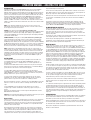
INTRODUCTION
The ADASTRA 900 series of amplifiers are designed for industrial use in factories,
offices and public buildings. Two (952.966) or three (952.969 and 952.972) microphone
inputs are provided. In addition a LINE input is also available which can be used for
music sources and similar higher signal sources. There is also an output suitable for
feeding the ADASTRA 952.975 slave amplifier in the same series thus making amplifier
stacking a possibility. Provision is made for connecting to either 100 volts to line or low
impedance loudspeakers. The amplifier can be used from either a 220-volt AC or a 24-
volt DC power source. Within the packaging will be found a 3 core 230-volt mains lead
terminated with a IEC connector at one end and a 13 amp plug top fused at 5 amps at
the other.
NOTE: If you are connecting the amplifier to two-wire power source i.e. have no earth
pin available then essential that a suitable wire is run from the chassis binding post
adjacent to the mains lead on the rear to a proven earth.
FRONT PANEL viewed from left to right. See the front page for a diagram.
Three controlled channels are provided.
MIC 1 and MIC 2 are on the extreme left with the LINE, BASS and TREBLE cut controls
towards the right hand side. The MASTER control is next with the signal monitoring and
the mains on/off switch at the extreme right.
REAR PANEL viewed from left to right. See the front page for a diagram.
On the left is found the IEC input incorporating a mains fuse. Next is the chassis binding
post with the DC input terminals adjacent to the loudspeaker termination. Towards the
right there is the SLAVE OUT phono socket which can be used for recording purposes.
Next are the LINE OUT and LINE IN sockets followed by the mono jack socket for MIC 2
with the VOX (ducking) on/off switch adjacent. At the extreme right is the XLR3 socket
for MIC 1.
See the specification panel for full technical details.
PROTECTION The amplifier is automatically protected for short, open circuit and
overheating. A short or open circuit on the loudspeaker line is indicated by the POWER
indicator pulsing slowly on and off. Overheating in excess of 105°C is protected by a
thermal cut out and if this occurs then the amplifier will cut out completely. The cause
is usually by the placing of papers on top of the amplifier or by enclosing it in a poorly
ventilated place. If this happens remove any restrictions on ventilation and leave the
amplifier switched off for five minutes. This will restore the protection circuits to their
monitoring mode. If the fault had existed for some time then the fuse located adjacent
to the IEC connector on the rear panel may also need replacement. In this case the
POWER indication on the front panel will fail to illuminate.
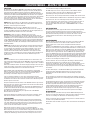
INSTALLATION
MIC1 is for a balanced microphone on an XLR3 socket: twin screened wire (ADASTRA
Z3 or Z323) should be used for connection. Termination follows the convention i.e. pin 1
– Screening; pin 2 - Signal go; pin 3 – Signal return.
MIC 1 has the added facility of being able to duck all other inputs on the presence of a
signal. No additional wiring is required and the switch to activate this facility (VOX) will
be found at the rear.
MIC 2, and MIC 3 when fitted, are for unbalanced low impedance microphones and are
terminated with rear mounted jack sockets. Single screened wire (ADASTRA Z1 or Z21)
should be used for connection the inner core being connected to the tip with the outer
screening to the body of the mono jack plug.
If it is necessary to connect balanced microphone to one of the unbalanced inputs then
of the two inner screened wires one should be connected to the jack plug tip whilst the
other is connected to the jack plug body together with the outer screening.
Compact disc and tape players will use the LINE IN phono (RCA) socket and need to be
terminated with a phono (RCA) plug, the live (inner) wire going to the central pin with
the outer screening being soldered to the body.
If a recording facility is required then suitable feed can be found by using the SLAVE
OUT socket at the rear. Connect as for players (see above)
This socket can also be used for distributing a signal to up to ten ADASTRA 952.975
slave amplifiers.
Caution Care must be taken when fitting any connectors to avoid damaging the cable or
the connector through excessive heat from the soldering tool.
LOUDSPEAKERS
All connections to the loudspeaker terminals should be made suing suitable spade lugs
crimped or soldered to the loudspeaker cables. Any other method can give rise to short
circuit. There is provision for both 100 volts line and low impedance loudspeakers but it
is not advisable to use both together.
Low Impedance loudspeakers should he connected in a series parallel arrangement
such that the total load is never less than 8 ohm. i.e. two 4 ohm loudspeakers could be
connected in series and connected between the common and the 8 ohm tap. Care
should be taken with this arrangement that the volume level is carefully controlled, as it
is possible to damage loudspeakers by using too high a volume setting.
The 100 volt line loudspeakers should be connected to the common and the 100 volt
line terminals taking care that the sum of the wattage of all the loudspeakers on he line
does not exceed the total power available from the amplifier.
Please Note that all the loudspeaker terminals are fully floating with respect to chassis.
In the event of cross talk to other services or instability then it may be beneficial if the
‘com’ terminal is strapped to the earth binding post.
Please remember that a low impedance loudspeaker system requires heavy cable
feeding the loudspeakers to minimize losses. For a widespread installation (i.e. a
factory system) it is far better and more cost effective to use the 100 volt line system-
See ADASTRAGEN sheet no. 5 for further information.
MOUNTING BRACKETS.
These will be found in the packaging with the mains lead. The mounting holes can be
used in one of two ways:
1. As ears for use when mounting the amplifier into an equipment rack.
2. To mount the amplifier on top of a shelf.
BATTERY OPERATION
A 24V (for 120W, 952.972 & 952.975) or a 12V (for 30W, 952.966 & 60W, 952.969)
battery can be connected using suitable spade lugs crimped and soldered to the battery
cables. Care must be taken to ensure that the terminals lie in the spaces provided and
do not swing to one side and thus short out on the mounting screws. Polarity should be
observed when connecting to the amplifier although there is reverse polarity protection.
The power output will be reduced on battery working, the output also depending on the
state of the battery.
Please note that the power switch does not control the 12V/24V supply to the amplifier.
If battery On/Off control is required then a separate switch will need to be installed
remote to the amplifier.
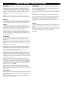
SETTING UP
When all connections have been made, check that all controls are at zero then plug the
mains lead provided into the amplifier and the 13 amp plug top into a suitable 230 volt
socket. Depress the double pole power switch on the right-hand side of the front panel.
Observe that the POWER LED illuminates.
Advance the MASTER control to 6 on its scale then using a local microphone in MIC 1
socket slowly advance its volume control whilst speaking into the microphone. Observe
the SIGNAL indicator on the right hand side whilst doing so. As the control is advanced
the indicator will start flashing in time with the peaks of speech. This indicates that a
signal is being passed to the loudspeakers. The control should be set such that the
peaks of sound keep the SIGNAL indicator almost continuously lit but that the PEAK
indicator only shows on rare occasions or not at all.Continuous illumination of the PEAK
led indicates that the amplifier is being overloaded. If the MIC 1 control is at maximum
without achieving the desired output then it will be necessary to increase the MASTER
setting a little and recommence the setting up procedure until a satisfactory level of
output is achieved.
It may be that, before this setting can be achieved, a howl-round point is reached
where the system appears to become unstable, if this is so then the nearest
loudspeaker and the microphone you are using are in each others’ sound fields and
need to be repositioned the one with the other. If the 100 volt line system is being
employed you can reset the nearer loudspeaker to a lower wattage tap to minimize the
howl-round.
The object of this setting-up exercise is to balance the MASTER and MIC 1 controls
such that neither is at a very low or a very high setting in relation to each other. When
this initial setting-tip procedure has been completed try the other input channels in a
similar manner. Make a note of the control settings for future reference.
Most tape and CD players have additional level controls of their which can be usefully
employed to fine balance their volume levels with the LINE or the AUX control.
The bass and treble cut controls should initially be set to their minimum (anti-
clockwise) positions for setting up. Once this has been carried out then these can be
set for personal taste. However when speech is being transmitted into a noisy or
reverberant environment then intelligence can he significantly improved by rotating the
bass cut control fully clockwise. When horn type loudspeakers are in use then the
control must be set fully clockwise to minimize the risk of low frequency damage to
the loudspeakers.
INTERFERENCE
Whilst this equipment complies in all respects with EMC legislation its use in an
industrial environment where there are many potential sources of interference means
that steps may need to be taken to minimize any difficulties.
Always check that the amplifier has a good earth. In the event of interference secure
the services of a qualified electrician to carry out tests on the socket in use to ensure
that a low resistance earth path exists.
Do not position the amplifier very close to large transformers. television monitors and
computers
OPERATION MANUAL - ADASTRA 900 SERIES
GB
WARNING: DO NOT CONNECT THE MAINS SUPPLY TO THE AMPLIFIER UNTIL ALL
THE NECESSARYINPUT AND OUTPUT CONNECTIONS HAVE BEEN MADE.
CIRCUIT DIAGRAMS ARE AVAILABLE ON REQUEST
Page is loading ...
Page is loading ...
Page is loading ...
Page is loading ...
-
 1
1
-
 2
2
-
 3
3
-
 4
4
-
 5
5
-
 6
6
-
 7
7


Skytronics 952.969 Mixer Amplifier 4 Channel 60 W Specification
- Category
- AV receivers
- Type
- Specification
Ask a question and I''ll find the answer in the document
Finding information in a document is now easier with AI
in other languages
Other documents
-
Pulse MA-360 User manual
-
Adastra 952.993 Operating instructions
-
LY International Electronics PB-9811P Owner's manual
-
-
Adastra ML622 User manual
-
 DSPPA MP1000P II Owner's manual
-
-
Adastra RS240 User manual
-
-
